height NISSAN X-TRAIL 2003 Electronic Repair Manual
[x] Cancel search | Manufacturer: NISSAN, Model Year: 2003, Model line: X-TRAIL, Model: NISSAN X-TRAIL 2003Pages: 3066, PDF Size: 51.47 MB
Page 552 of 3066
![NISSAN X-TRAIL 2003 Electronic Repair Manual AT-546
[ALL]
ASSEMBLY
4. Measure dimensions “1” and “2” at side cover and then cal-
culate dimension “A”.
lMeasure dimension “1”and“2” in at least two places.
5. Measure dimensions NISSAN X-TRAIL 2003 Electronic Repair Manual AT-546
[ALL]
ASSEMBLY
4. Measure dimensions “1” and “2” at side cover and then cal-
culate dimension “A”.
lMeasure dimension “1”and“2” in at least two places.
5. Measure dimensions](/img/5/57402/w960_57402-551.png)
AT-546
[ALL]
ASSEMBLY
4. Measure dimensions “1” and “2” at side cover and then cal-
culate dimension “A”.
lMeasure dimension “1”and“2” in at least two places.
5. Measure dimensions “
2”and“3” and then calculate dimen-
sion “B”.
lMeasure “2”and“3” in at least two places.
6. Select proper thickness of adjusting shim so that output shaft
end play (clearance between side cover and output shaft bear-
ing) is within specifications.
7. Install adjusting shim on output shaft bearing.
Assembly (2)ECS004MF
1. Apply locking sealant (Loctite #518) to transmission case as
shown in illustration.“A” : Distance between transmission case fitting
surface and adjusting shim mating surface.
A=
1-2
2
:Height of gauge
SAT374F
“B” : Distance between the end of output shaft bear-
ing outer race and the side cover fitting surface
of transmission case.
B=
2-3
2
:Height of gauge
SAT375F
Output shaft end play (A-B) :
0 - 0.15 mm (0 - 0.0059 in)
Output shaft end play adjusting shims :
Refer toAT-563, "
SERVICE DATA AND SPECIFICA-
TIONS (SDS)".
SAT440D
SAT441D
Page 745 of 3066

BL-1
BODY, LOCK & SECURITY SYSTEM
IBODY
CONTENTS
C
D
E
F
G
H
J
K
L
M
SECTION
A
B
BL
BODY, LOCK & SECURITY SYSTEM
PRECAUTIONS .......................................................... 3
Precautions .............................................................. 3
HOOD ......................................................................... 4
Fitting Adjustment .................................................... 4
FRONT END HEIGHT ADJUSTMENT AND LAT-
ERAL/LONGITUDIAL CLEARANCE ADJUST-
MENT .................................................................... 4
SURFACE HEIGHT ADJUSTMENT ..................... 4
Removal and Installation of Hood Assembly ............ 5
Removal and Installation of Hood Lock Control ....... 6
REMOVAL ............................................................. 6
INSTALLATION ..................................................... 7
Hood Lock Control Inspection .................................. 7
DOOR ......................................................................... 8
Fitting Adjustment .................................................... 8
FRONT DOOR ...................................................... 8
REAR DOOR ........................................................ 8
STRIKER ADJUSTMENT ..................................... 9
Removal and Installation .......................................... 9
Door Weatherstrip .................................................. 10
POWER DOOR LOCK SYSTEM ...............................11
System Description .................................................11
OPERATION ........................................................11
Component Parts and Harness Connector Location....11
Schematic .............................................................. 12
Wiring Diagram — D/LOCK — ............................... 13
Terminal and Reference Value for Time Control Unit... 17
Symptom Chart ...................................................... 17
Power Supply and Ground Circuit Check ............... 18
Door Lock/Unlock Switch Check ............................ 18
Door Key Cylinder Switch Check ........................... 19
Door Lock Actuator Check ..................................... 20
Door Switch Check ................................................. 21
Door Unlock Sensor Check .................................... 22
Key Switch Check .................................................. 23
POWER DOOR LOCK — SUPER LOCK — ............ 24
System Description ................................................ 24
OUTLINE ............................................................. 24
OPERATION ....................................................... 24
Schematic .............................................................. 26Wiring Diagram — S/LOCK — ............................... 27
Terminal and Reference Value for Time Control Unit... 33
Trouble Diagnoses ................................................. 34
PRELIMINARY CHECK ....................................... 34
SYMPTOM CHART ............................................. 35
Power Supply and Ground Circuit Check ............... 36
Door Lock/Unlock Switch Check ............................ 36
Door Key Cylinder Switch Check ............................ 37
Door Lock Actuator Check ...................................... 38
Door Switch Check ................................................. 39
Door Unlock Sensor Check .................................... 40
Key Switch Check ................................................... 41
Super Lock Actuator Check .................................... 42
NATS Release Signal Check .................................. 43
Ignition Switch “ON” Circuit Check ......................... 44
Remote Controller Signal Check ............................ 44
MULTI-REMOTE CONTROL SYSTEM ..................... 45
Component Parts and Harness Connector Location... 45
System Description ................................................. 45
FUNCTION .......................................................... 45
LOCK OPERATION ............................................. 45
UNLOCK OPERATION ........................................ 46
HAZARD REMINDER ......................................... 46
MULTI-REMOTE CONTROLLER ID CODE
ENTRY ................................................................ 46
Wiring Diagram — MULTI — .................................. 47
Terminal and Reference Value for Multi-remote
Control Unit ............................................................. 49
Symptom Chart ....................................................... 49
Remote Controller Battery Check ........................... 49
Power Supply and Ground Circuit Check ............... 50
Hazard Reminder Check ........................................ 51
ID Code Entry Procedure ....................................... 52
Remote Controller Battery Replacement ................ 53
FRONT DOOR LOCK ............................................... 54
Component Parts Location ..................................... 54
Inspection and Adjustment ..................................... 54
OUT SIDE HANDLE ROD ADJUSTMENT .......... 54
Removal and Installation ........................................ 54
REMOVAL ........................................................... 54
Page 748 of 3066
BL-4
HOOD
HOOD
PFP:65100
Fitting AdjustmentEIS000KF
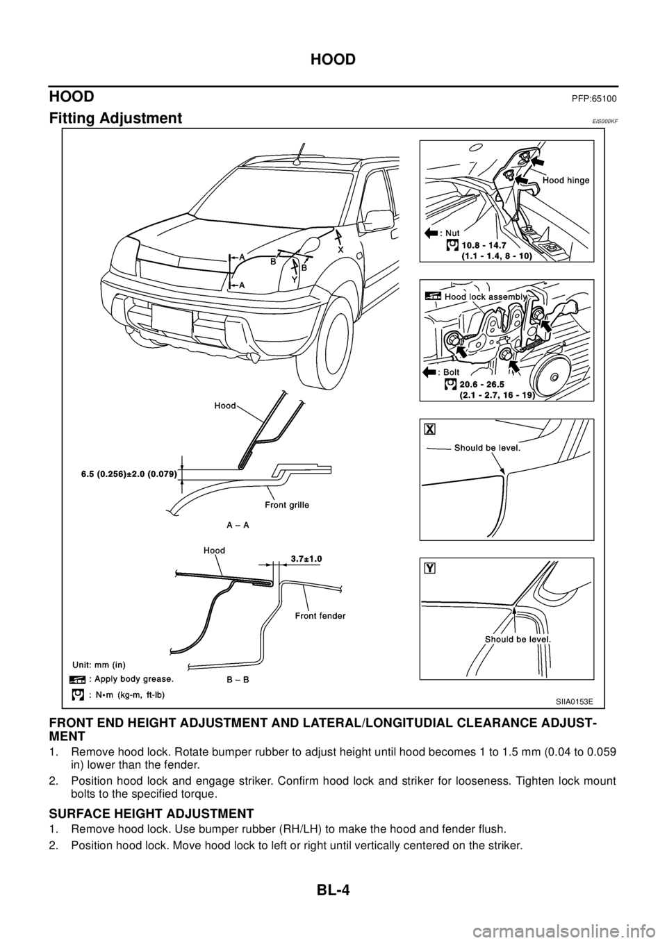
FRONT END HEIGHT ADJUSTMENT AND LATERAL/LONGITUDIAL CLEARANCE ADJUST-
MENT
1. Remove hood lock. Rotate bumper rubber to adjust height until hood becomes 1 to 1.5 mm (0.04 to 0.059
in) lower than the fender.
2. Position hood lock and engage striker. Confirm hood lock and striker for looseness. Tighten lock mount
bolts to the specified torque.
SURFACE HEIGHT ADJUSTMENT
1. Remove hood lock. Use bumper rubber (RH/LH) to make the hood and fender flush.
2. Position hood lock. Move hood lock to left or right until vertically centered on the striker.
SIIA0153E
Page 749 of 3066
HOOD
BL-5
C
D
E
F
G
H
J
K
L
MA
B
BL
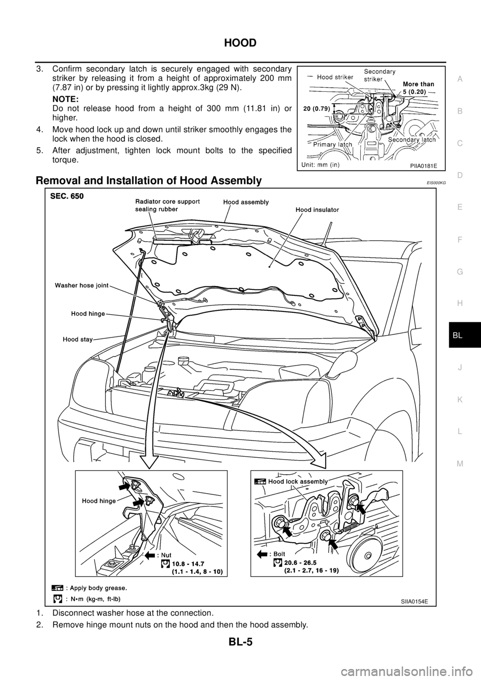
3. Confirm secondary latch is securely engaged with secondary
striker by releasing it from a height of approximately 200 mm
(7.87 in) or by pressing it lightly approx.3kg (29 N).
NOTE:
Do not release hood from a height of 300 mm (11.81 in) or
higher.
4. Move hood lock up and down until striker smoothly engages the
lock when the hood is closed.
5. After adjustment, tighten lock mount bolts to the specified
torque.
Removal and Installation of Hood AssemblyEIS000KG
1. Disconnect washer hose at the connection.
2. Remove hinge mount nuts on the hood and then the hood assembly.
PIIA0181E
SIIA0154E
Page 751 of 3066
HOOD
BL-7
C
D
E
F
G
H
J
K
L
MA
B
BL
INSTALLATION
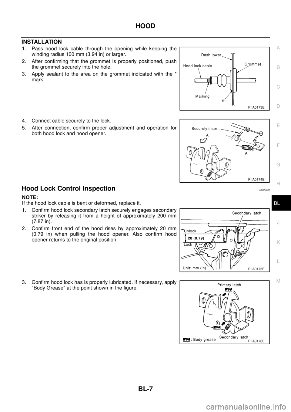
1. Pass hood lock cable through the opening while keeping the
winding radius 100 mm (3.94 in) or larger.
2. After confirming that the grommet is properly positioned, push
the grommet securely into the hole.
3. Apply sealant to the area on the grommet indicated with the *
mark.
4. Connect cable securely to the lock.
5. After connection, confirm proper adjustment and operation for
both hood lock and hood opener.
Hood Lock Control InspectionEIS000KI
NOTE:
If the hood lock cable is bent or deformed, replace it.
1. Confirm hood lock secondary latch securely engages secondary
striker by releasing it from a height of approximately 200 mm
(7.87 in).
2. Confirm front end of the hood rises by approximately 20 mm
(0.79 in) when pulling the hood opener. Also confirm hood
opener returns to the original position.
3. Confirm hood lock has is properly lubricated. If necessary, apply
"Body Grease" at the point shown in the figure.
PIIA0173E
PIIA0174E
PIIA0175E
PIIA0176E
Page 752 of 3066
BL-8
DOOR
DOOR
PFP:80100
Fitting AdjustmentEIS000KJ
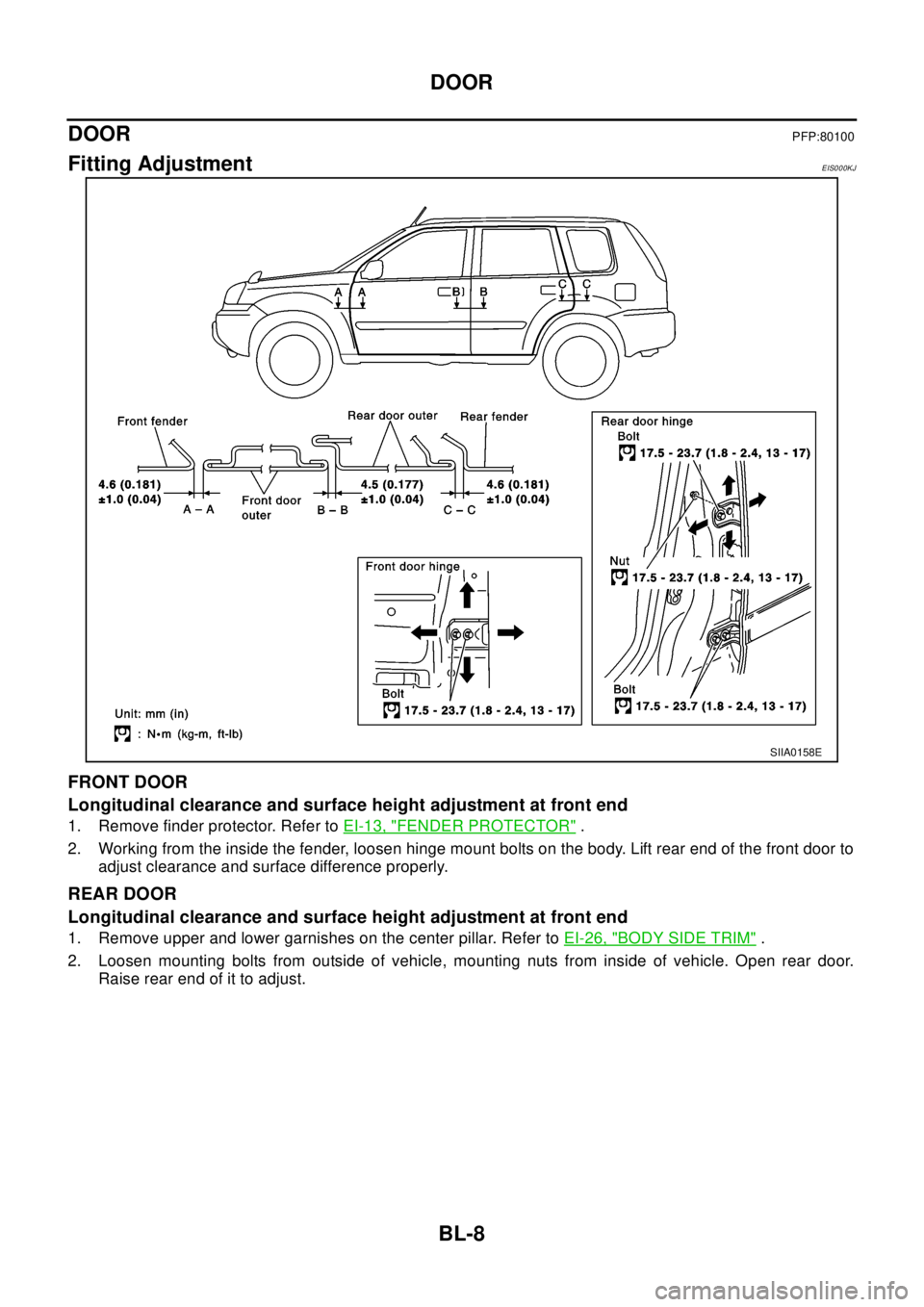
FRONT DOOR
Longitudinal clearance and surface height adjustment at front end
1. Remove finder protector. Refer toEI-13, "FENDER PROTECTOR".
2. Working from the inside the fender, loosen hinge mount bolts on the body. Lift rear end of the front door to
adjust clearance and surface difference properly.
REAR DOOR
Longitudinal clearance and surface height adjustment at front end
1. Remove upper and lower garnishes on the center pillar. Refer toEI-26, "BODY SIDE TRIM".
2. Loosen mounting bolts from outside of vehicle, mounting nuts from inside of vehicle. Open rear door.
Raise rear end of it to adjust.
SIIA0158E
Page 840 of 3066
BR-6
BRAKE PEDAL
BRAKE PEDAL
PFP:46501
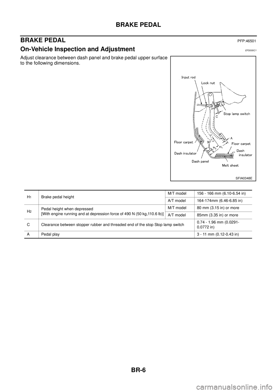
On-Vehicle Inspection and AdjustmentEFS000C1
Adjust clearance between dash panel and brake pedal upper surface
to the following dimensions.
SFIA0348E
H1Brake pedal heightM/T model 156 - 166 mm (6.10-6.54 in)
A/T model 164-174mm (6.46-6.85 in)
H
2Pedal height when depressed
[With engine running and at depression force of 490 N (50 kg,110.6 lb)]M/T model 80 mm (3.15 in) or more
A/T model 85mm (3.35 in) or more
C Clearance between stopper rubber and threaded end of the stop Stop lamp switch0.74 - 1.96 mm (0.0291-
0.0772 in)
A Pedal play3 - 11 mm (0.12-0.43 in)
Page 841 of 3066
BRAKE PEDAL
BR-7
C
D
E
G
H
I
J
K
L
MA
B
BR
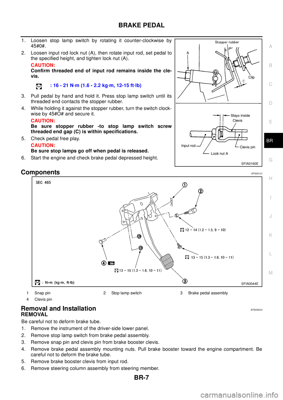
1. Loosen stop lamp switch by rotating it counter-clockwise by
45#0#.
2. Loosen input rod lock nut (A), then rotate input rod, set pedal to
the specified height, and tighten lock nut (A).
CAUTION:
Confirm threaded end of input rod remains inside the cle-
vis.
3. Pull pedal by hand and hold it. Press stop lamp switch until its
threaded end contacts the stopper rubber.
4. While holding it against the stopper rubber, turn the switch clock-
wise by 45#O# and secure it.
CAUTION:
Be sure stopper rubber -to stop lamp switch screw
threaded end gap (C) is within specifications.
5. Check pedal free play.
CAUTION:
Be sure stop lamps go off when pedal is released.
6. Start the engine and check brake pedal depressed height.
ComponentsEF S0 01 CI
Removal and InstallationEFS000C2
REMOVAL
Be careful not to deform brake tube.
1. Remove the instrument of the driver-side lower panel.
2. Remove stop lamp switch from brake pedal assembly.
3. Remove snap pin and clevis pin from brake booster clevis.
4. Remove brake pedal assembly mounting nuts. Pull brake booster toward the engine compartment. Be
careful not to deform the brake tube.
5. Remove brake booster clevis from input rod.
6. Remove steering column assembly from steering member.: 16 - 21 N·m (1.6 - 2.2 kg·m, 12-15 ft·lb)
SFIA0160E
SFIA0044E
1 Snap pin 2 Stop lamp switch 3 Brake pedal assembly
4 Clevis pin
Page 852 of 3066
BR-18
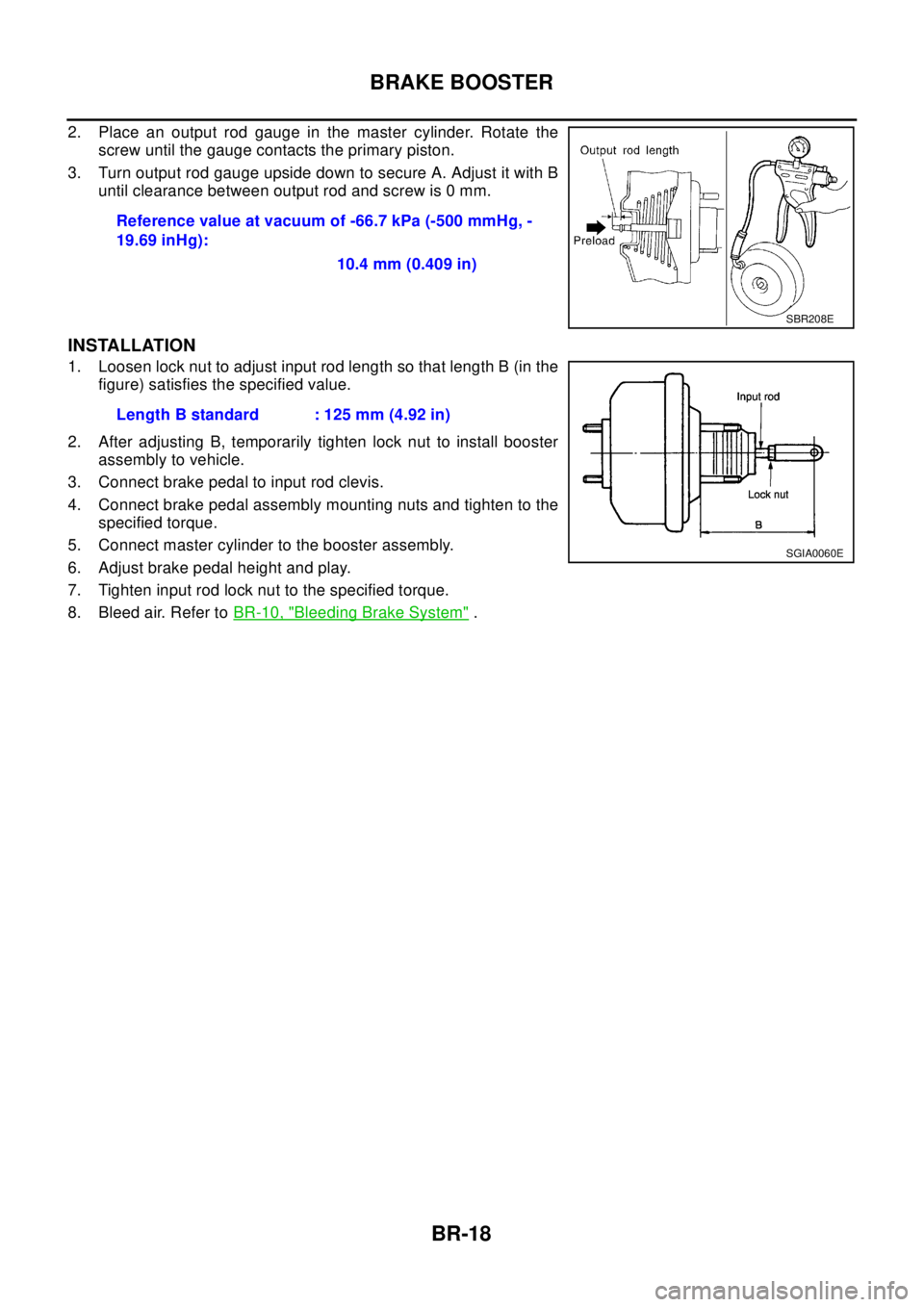
BRAKE BOOSTER
2. Place an output rod gauge in the master cylinder. Rotate the
screw until the gauge contacts the primary piston.
3. Turn output rod gauge upside down to secure A. Adjust it with B
until clearance between output rod and screw is 0 mm.
INSTALLATION
1. Loosen lock nut to adjust input rod length so that length B (in the
figure) satisfies the specified value.
2. After adjusting B, temporarily tighten lock nut to install booster
assembly to vehicle.
3. Connect brake pedal to input rod clevis.
4. Connect brake pedal assembly mounting nuts and tighten to the
specified torque.
5. Connect master cylinder to the booster assembly.
6. Adjust brake pedal height and play.
7. Tighten input rod lock nut to the specified torque.
8. Bleed air. Refer toBR-10, "
Bleeding Brake System". Reference value at vacuum of -66.7 kPa (-500 mmHg, -
19.69 inHg):
10.4 mm (0.409 in)
SBR208E
Length B standard : 125 mm (4.92 in)
SGIA0060E
Page 867 of 3066

SERVICE DATA AND SPECIFICATIONS (SDS)
BR-33
C
D
E
G
H
I
J
K
L
MA
B
BR
SERVICE DATA AND SPECIFICATIONS (SDS)PFP:00030
General SpecificationsEFS000CQ
Brake PedalEFS000CR
Check ValveEF S0 00 CS
Brake BoosterEFS000CT
Vacuum type
Front Disc BrakeEFS000CU
Front brakeBrake model AD31VD
Cylinder bore diameter 44.4´2(1.748´0.08)
Pad
Length x width x thickness132.0´52.5´11 . 0
(5.20´2.067´0.433)
Rotor outer diameter x thickness 280´28 (11.02´1.10)
Rear brakeBrake model ADV9VA
Cylinder bore diameter 34.9 (1.374)
Pad
Length x width x thickness83.0´33.0´8.5
(3.268´1.299´0.335)
Rotor outer diameter x thickness 292´16 (11.50´0.63)
Master cylinder Cylinder bore diameter 25.4 (1)
Control valve Valve model Electronic control type
Brake booster Booster model C215T
Diaphragm diameterPrimary 230 (9.06)
Secondary 205 (8.07)
Recommended brake fluid DOT 3 or DOT 4
Free play (at pedal top surface) 3 - 11 mm (0.12 - 0.43 in)
Looseness at clevis pin (at pedal top surface) 1 - 3 mm (0.04 - 0.12 in)
Brake pedal height (from dash panel top surface)M/T model 156 - 166 mm (6.14 - 6.54 in)
A/T model 164 - 174 mm (6.46 - 6.85 in)
Depressed pedal height under force of 490 N (50 kg,110.6 lb)
(from dash panel top surface)M/T model 80 mm (3.15 in) or more
A/T model 85 mm (3.35 in) or more
Clearance between threaded end of stop lamp switch and pedal stopper 0.74 - 1.96 mm (0.0291 - 0.0772 in)
Vacuum leakage [at vacuum of 66.7 kPa (-500 mmHg, -19.69
inHg)]Within 1.3 kPa (10 mmHg, 0.39 inHg) of vacuum for 15 sec-
onds
Vacuum leakage [at vacuum of -66.7 kPa (-500 mmHg, -19.69
inHg)]Within 3.3 kPa (25 mmHg, 0.98 inHg) of vacuum for 15 sec-
onds
Input rod installation standard dimension 125 mm (4.92 in)
Brake typeAD31VD
Brake padStandard thickness (new) 11 mm (0.43 in)
Repair limit thickness 2.0 mm (0.07 in)
Disc rotorStandard thickness (new) 28 mm (1.10 in)
Repair limit thickness 26 mm (1.02 in)
Runout limit 0.04 mm (0.0016 in)