service NISSAN X-TRAIL 2003 Electronic Manual PDF
[x] Cancel search | Manufacturer: NISSAN, Model Year: 2003, Model line: X-TRAIL, Model: NISSAN X-TRAIL 2003Pages: 3066, PDF Size: 51.47 MB
Page 719 of 3066

REFRIGERANT LINES
ATC-141
C
D
E
F
G
H
I
K
L
MA
B
AT C
CAUTION:
Moving the electronic leak detector probe slower and closer to the suspected leak area will improve
the chances of finding a leak.
Checking System for Leaks Using the Fluorescent Leak DetectorEJS000VK
1. Check A/C system for leaks using the UV lamp and safety glasses (J-42220) in a low sunlight area (area
without windows preferable). Illuminate all components, fittings and lines. The dye will appear as a bright
green/yellow area at the point of leakage. Fluorescent dye observed at the evaporator drain opening indi-
cates an evaporator core assembly (tubes, core or TXV) leak.
2. If the suspected area is difficult to see, use an adjustable mirror or wipe the area with a clean shop rag or
cloth, with the UV lamp for dye residue.
3. After the leak is repaired, remove any residual dye using dye cleaner (J-43872) to prevent future misdiag-
nosis.
4. Perform a system performance check and verify the leak repair with an approved electronic refrigerant
leak detector.
NOTE:
Other gases in the work area or substances on the A/C components, for example, anti-freeze, windshield
washer fluid, solvents and lubricants, may falsely trigger the leak detector. Make sure the surfaces to be
checked are clean.
Clean with a dry cloth or blow off with shop air.
Do not allow the sensor tip of the detector to contact with any substance. This can also cause false readings
and may damage the detector.
Dye InjectionEJS000VL
(This procedure is only necessary when recharging the system or when the compressor has seized and was
replaced.)
1. Check A/C system static (at rest) pressure. Pressure must be at least 345 kPa (50 psi).
2. Pour one bottle (1/4 ounce / 7.4 cc) of the A/C refrigerant dye into the injector tool (J-41459).
3. Connect the injector tool to the A/C LOW PRESSURE side service fitting.
4. Start engine and switch A/C ON.
5. When the A/C operating (compressor running), inject one bottle (1/4 ounce / 7.4 cc) of fluorescent dye
through the low-pressure service valve using dye injector tool J-41459 (refer to the manufacture's operat-
ing instructions).
6. With the engine still running, disconnect the injector tool from the service fitting.
CAUTION:
Be careful the A/C system or replacing a component, pour the dye directly into the open system con-
nection and proceed with the service procedures.
7. Operate the A/C system for a minimum of 20 minutes to mix the dye with the system oil. Depending on the
leak size, operating conditions and location of the leak, it may take from minutes to days for the dye to
penetrate a leak and become visible.
Electronic Refrigerant Leak DetectorEJS000VM
PRECAUTIONS FOR HANDLING LEAK DETECTOR
When performing a refrigerant leak check, use an A/C leak detector
or equivalent. Ensure that the instrument is calibrated and set prop-
erly per the operating instructions.
The leak detector is a delicate device. In order to use the leak detec-
tor properly, read the operating instructions and perform any speci-
fied maintenance.
SHA705EB
Page 720 of 3066
ATC-142
REFRIGERANT LINES
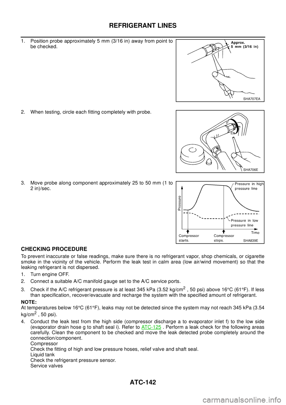
1. Position probe approximately 5 mm (3/16 in) away from point to
be checked.
2. When testing, circle each fitting completely with probe.
3. Move probe along component approximately 25 to 50 mm (1 to
2 in)/sec.
CHECKING PROCEDURE
To prevent inaccurate or false readings, make sure there is no refrigerant vapor, shop chemicals, or cigarette
smoke in the vicinity of the vehicle. Perform the leak test in calm area (low air/wind movement) so that the
leaking refrigerant is not dispersed.
1. Turn engine OFF.
2. Connect a suitable A/C manifold gauge set to the A/C service ports.
3. Check if the A/C refrigerant pressure is at least 345 kPa (3.52 kg/cm
2,50psi)above16°C(61°F).Ifless
than specification, recover/evacuate and recharge the system with the specified amount of refrigerant.
NOTE:
At temperatures below 16°C(61°F), leaks may not be detected since the system may not reach 345 kPa (3.54
kg/cm
2,50psi).
4. Conduct the leak test from the high side (compressor discharge a to evaporator inlet f) to the low side
(evaporator drain hose g to shaft seal i). Refer toATC-125
. Perform a leak check for the following areas
carefully. Clean the component to be checked and move the leak detected probe completely around the
connection/component.
Compressor
Check the fitting of high and low pressure hoses, relief valve and shaft seal.
Liquid tank
Check the refrigerant pressure sensor.
Service valves
SHA707EA
SHA706E
SHA839E
Page 721 of 3066
REFRIGERANT LINES
ATC-143
C
D
E
F
G
H
I
K
L
MA
B
AT C
Check all around the service valves. Ensure service valve caps are secured on the service valves (to pre-
vent leaks).
NOTE:
After removing A/C manifold gauge set from service valves, wipe any residue from valves to prevent any
false readings by leak detector.
Cooling unit (Evaporator)
With engine OFF, turn blower fan on "High" for at least 15 seconds to dissipate any refrigerant trace in the
cooling unit. Wait a minimum of 10 minutes accumulation time (refer to the manufacturer's recommended
procedure for actual wait time) before inserting the leak detector probe into the drain hose.
Keep the probe inserted for at least 10 seconds. Use caution not to contaminate the probe tip with water
or dirt that may be in the drain hose.
5. If a leak detector detects a leak, verify at least once by blowing compressed air into area of suspected
leak, then repeat check as outlined above.
6. Do not stop when one leak is found. Continue to check for additional leaks at all system components.
If no leaks are found, perform steps 7 - 10.
7. Start engine.
8. Set the heater A/C control as follows;
a. A/C switch: ON
b. Face mode
c. Intake position: Recirculation
d. Max cold temperature
e. Fan speed: High
9. Run engine at 1,500 rpm for at least 2 minutes.
10. Turn engine off and perform leak check again following steps 4 through 6 above.
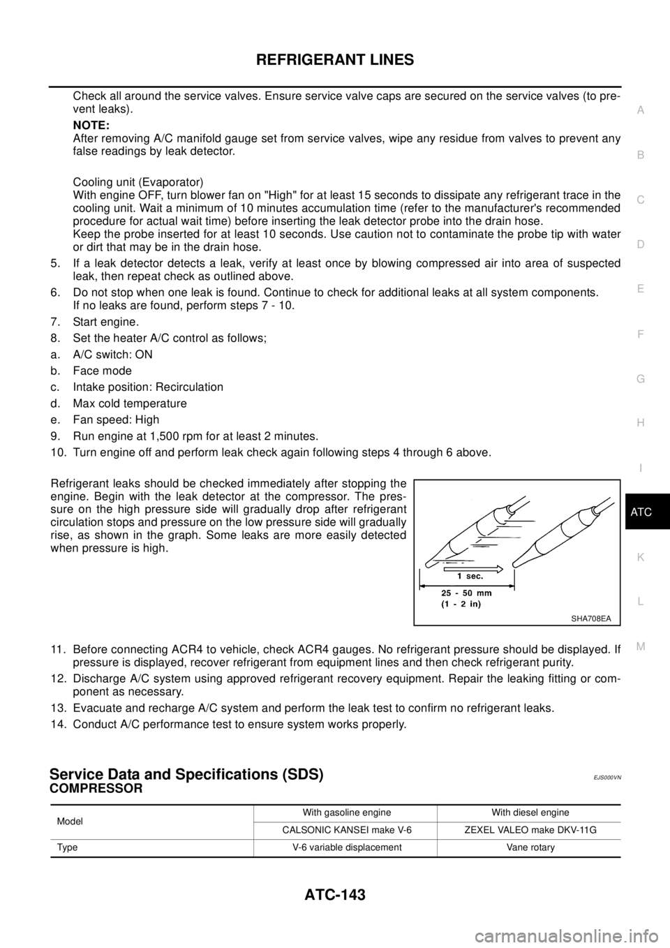
Refrigerant leaks should be checked immediately after stopping the
engine. Begin with the leak detector at the compressor. The pres-
sure on the high pressure side will gradually drop after refrigerant
circulation stops and pressure on the low pressure side will gradually
rise, as shown in the graph. Some leaks are more easily detected
when pressure is high.
11. Before connecting ACR4 to vehicle, check ACR4 gauges. No refrigerant pressure should be displayed. If
pressure is displayed, recover refrigerant from equipment lines and then check refrigerant purity.
12. Discharge A/C system using approved refrigerant recovery equipment. Repair the leaking fitting or com-
ponent as necessary.
13. Evacuate and recharge A/C system and perform the leak test to confirm no refrigerant leaks.
14. Conduct A/C performance test to ensure system works properly.
Service Data and Specifications (SDS)EJS000VN
COMPRESSOR
SHA708EA
ModelWith gasoline engine With diesel engine
CALSONIC KANSEI make V-6 ZEXEL VALEO make DKV-11G
Type V-6 variable displacement Vane rotary
Page 722 of 3066

ATC-144
REFRIGERANT LINES
LUBRICANT
REFRIGERANT
ENGINE IDLING SPEED
Refer toATC-144, "ENGINE IDLING SPEED".
BELT TENSION
Refer to,EM-13, "Tension Adjustment"QR engine;EM-110, "Tension Adjustment"YD engine.
Displacement
cm3 (cu. in)/revMax. 184 (11.228)
110 (6.71)
Min. 14.5 (0.885)
Cylinder bore´stroke
mm (in)37 (1.46)´[2.3 - 28.6 (0.091 - 1.126)] -
Direction of rotation Clockwise (viewed from drive end)
Drive beltPoly V
ModelWith gasoline engine With diesel engine
CALSONIC KANSEI make V-6 ZEXEL VALEO make DKV-11G
Name Nissan A/C System Oil Type S Nissan A/C System Oil Type R
Part number KLH00-PAGS0 KLH00-PAGR0
Capacity
ml (lmp fl oz)Total in system 180 (6.3)
Compressor (Service part) charging
amount180 (6.3)
Ty p eHFC-134a (R-134a)
Capacity
kg (lb)0.50 (1.10)
Page 724 of 3066
AV-2
PRECAUTIONS
PRECAUTIONS
PFP:00011
Precautions for Supplemental Restraint System (SRS) “AIR BAG” and “SEAT
BELT PRE-TENSIONER”
EKS0036C
The Supplemental Restraint System such as “AIR BAG” and “SEAT BELT PRE-TENSIONER”, used along
with a front seat belt, helps to reduce the risk or severity of injury to the driver and front passenger for certain
types of collision. Information necessary to service the system safely is included in the SRS and SB section of
this Service Manual.
WAR NIN G:
lTo avoid rendering the SRS inoperative, which could increase the risk of personal injury or death
in the event of a collision which would result in air bag inflation, all maintenance must be per-
formed by an authorized NISSAN/INFINITI dealer.
lImproper maintenance, including incorrect removal and installation of the SRS, can lead to per-
sonal injury caused by unintentional activation of the system. For removal of Spiral Cable and Air
Bag Module, see the SRS section.
lDo not use electrical test equipment on any circuit related to the SRS unless instructed to in this
Service Manual. SRS wiring harnesses can be identified by yellow harness connectors.
Wiring Diagrams and Trouble DiagnosisEKS0036D
When you read wiring diagrams, refer to the followings:
lRefer toGI-14, "How to Read Wiring Diagrams"in GI section
lRefer toPG-2, "POWER SUPPLY ROUTING"for power distribution circuit in PG section
When you perform trouble diagnosis, refer to the followings:
lRefer toGI-11, "HOW TO FOLLOW TEST GROUPS IN TROUBLE DIAGNOSES"in PG section
lRefer toGI-24, "How to Perform Efficient Diagnosis for an Electrical Incident"in PG section
Page 725 of 3066

AUDIO
AV-3
C
D
E
F
G
H
I
J
L
MA
B
AV
AUDIOP F P : 2 8 111
System DescriptionEKS002F2
Refer to Owner's Manual for audio system operating instructions.
Power is supplied at all times
lthrough 15A fuse (No. 32, located in the fusible link and fuse block)
lto audio unit terminal 3
lto CD auto changer terminal 32.
With the ignition switch in the ACC or ON position, power is supplied
lthrough 10A fuse [No. 4, located in the fuse block (J/B)]
lto audio unit terminal 6,
lto CD auto changer terminal 36
Ground is supplied through the case of the audio unit.
Audio signals are supplied
lthrough audio unit terminals 5, 7, 9, 10, 11, 13, 15, 16
lto terminals 1 and 2 of front door speaker LH and RH,
lto terminals 1 and 2 of rear door speaker LH and RH and
lto terminals 1 and 2 of tweeter LH and RH (with 6 speakers)
NATS AUDIO LINK
Description
The link with the NATS IMMU implies that the audio unit can basically only be operated if connected to the
matching NATS IMMU to which the audio unit was initially fitted on the production line.
Since radio operation is impossible after the link with the NATS is disrupted theft of the audio unit is basically
useless since special equipment is required to reset the audio unit.
Initialization process for audio units that are linked to the NATS IMMU
New audio units will be delivered to the factories in the “NEW” state, i.e. ready to be linked with the vehicle's
NATS. When the audio unit in “NEW” state is first switched on at the factory, it will start up communication with
the vehicle's immobilizer control unit (IMMU) and send a code (the “audio unit Code”) to the IMMU. The IMMU
will then store this code, which is unique to each audio unit, in its (permanent) memory.
Upon receipt of the code by the IMMU, the NATS will confirm correct receipt of the audio unit code to the audio
unit. Hereafter, the audio unit will operate as normal.
During the initialization process, “NEW” is displayed on the audio unit display. Normally though, communica-
tion between audio unit and IMMU takes such a short time (300 ms) that the audio unit seems to switch on
directly without showing “NEW” on its display.
Normal operation
Each time the audio unit is switched on afterwards, the audio unit code will be verified between the audio unit
and the NATS before the audio unit becomes operational. During the code verification process, “WAIT” is
shown on the audio unit display. Again, the communication takes such a short time (300 ms) that the audio
unit seems to switch on directly without showing “WAIT” on its display.
When the radio is locked
In case of a audio unit being linked with the vehicle's NATS (immobilizer system), disconnection of the link
between the audio unit and the IMMU will cause the audio unit to switch into the lock (“SECURE”) mode in
which the audio unit is fully inoperative. Hence, repair of the audio unit is basically impossible, unless the
audio unit is reset to the “NEW” state for which special decoding equipment is required.
Clarion has provided their authorized service representatives with so called “decoder boxes” which can bring
the audio unit back to the “NEW” state, enabling the audio unit to be switched on after which repair can be car-
ried out. Subsequently, when the repaired audio unit is delivered to the final user again, it will be in the “NEW”
state to enable re-linking the audio unit to the vehicle's immobilizer system. As a result of the above, repair of
the audio unit can only be done by an authorized Clarion representative (when the owner of the vehicle
requests repair and can show personal identification).
Page 726 of 3066

AV-4
AUDIO
Service Procedure
SPEED DEPENDENT VOLUME CONTROL
Description
If activated, the radio output volume will be automatically adjusted to compensate for increased driving noises
at higher driving speeds.
The radio receives a speed signal from the vehicle speed sensor (VSS) and selects the output volume.
PERSONAL AUDIO SETTINGS
Description
The radio is designed to store several settings (volume, bass, treble, preset stations and level of speed depen-
dent volume control) with every NATS ignition key used. Up to a maximum of 4 NATS keys can be registered.
During the communication mentioned under “Anti-Theft System”, the radio will recognize the used ignition key
and select the accompanying settings.
Item Service procedure Description
Battery disconnection No additional action required. —
Radio needs repair Repair needs to be done by authorized
representative of radio manufacturer since
radio cannot be operated unless it is reset
to NEW state, using special decoding
equipment.—
Replacement of radio by new part No additional action required. Radio is delivered in NEW state.
Transferring radio to another vehicle/
replacement of radio by an “old” partRadio needs to be reset to NEW state by
authorized representative of radio manu-
facturer.—
Replacement of IMMU Radio needs to be reset to NEW state by
authorized representative of Clarion.After switching on the radio, it will display
“SECURE” after 1 minute.
No communication from IMMU to radio 1. If NATS is malfunctioning, check NATS
system.
2. After NATS is repaired, reset radio to
NEW state by authorized representative
of Clarion.After switching on the radio, the radio will
display “SECURE” after 1 minute. Further
use of radio is impossible until communica-
tion is established again, or after radio is
reset by authorized representative of Clar-
ion.
When initialized between ECM and IMMU. Radio needs to be reset to NEW status by
authorized representative of Clarion.After switching on the radio, it will display
“SECURE” after 1 minute.
Page 740 of 3066
BCS-2
PRECAUTIONS
PRECAUTIONS
PFP:00011
Precautions for Supplemental Restraint System (SRS) “AIR BAG” and “SEAT
BELT PRE-TENSIONER”
EKS00369
The Supplemental Restraint System such as “AIR BAG” and “SEAT BELT PRE-TENSIONER”, used along
with a front seat belt, helps to reduce the risk or severity of injury to the driver and front passenger for certain
types of collision. Information necessary to service the system safely is included in the SRS and SB section of
this Service Manual.
WAR NIN G:
lTo avoid rendering the SRS inoperative, which could increase the risk of personal injury or death
in the event of a collision which would result in air bag inflation, all maintenance must be per-
formed by an authorized NISSAN/INFINITI dealer.
lImproper maintenance, including incorrect removal and installation of the SRS, can lead to per-
sonal injury caused by unintentional activation of the system. For removal of Spiral Cable and Air
Bag Module, see the SRS section.
lDo not use electrical test equipment on any circuit related to the SRS unless instructed to in this
Service Manual. SRS wiring harnesses can be identified by yellow harness connectors.
Wiring Diagrams and Trouble DiagnosisEKS0036B
When you read wiring diagrams, refer to the followings:
lRefer toGI-14, "How to Read Wiring Diagrams"in GI section.
lRefer toPG-2, "POWER SUPPLY ROUTING"for power distribution circuit in PG section.
When you perform trouble diagnosis, refer to the followings:
lRefer toGI-11, "HOW TO FOLLOW TEST GROUPS IN TROUBLE DIAGNOSES"in GI section.
lRefer toGI-24, "How to Perform Efficient Diagnosis for an Electrical Incident"in GI section.
Page 793 of 3066
MULTI-REMOTE CONTROL SYSTEM
BL-49
C
D
E
F
G
H
J
K
L
MA
B
BL
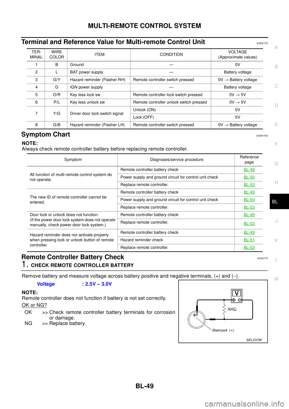
Terminal and Reference Value for Multi-remote Control UnitEIS001TQ
Symptom ChartEIS001RG
NOTE:
Always check remote controller battery before replacing remote controller.
Remote Controller Battery CheckEIS0 01T 3
1.CHECK REMOTE CONTROLLER BATTERY
Remove battery and measure voltage across battery positive and negative terminals, (+) and (-).
NOTE:
Remote controller does not function if battery is not set correctly.
OK or NG?
OK >> Check remote controller battery terminals for corrosion
or damage.
NG >> Replace battery.
TER-
MINALWIRE
COLORITEM CONDITIONVOLTAGE
(Approximate values)
1 B Ground — 0V
2 L BAT power supply — Battery voltage
3 G/Y Hazard reminder (Flasher RH) Remote controller switch pressed 0V®Battery voltage
4 G IGN power supply — Battery voltage
5 O/R Key less lock sw Remote controller lock switch pressed 0V®5V
6 P/L Key less unlock sw Remote controller unlock switch pressed 0V®5V
7 Y/G Driver door lock switch signalUnlock (ON) 0V
Lock (OFF) 5V
8 G/B Hazard reminder (Flasher LH) Remote controller switch pressed 0V®Battery voltage
Symptom Diagnoses/service procedureReference
page
All function of multi-remote control system do
not operate.Remote controller battery checkBL-49
Power supply and ground circuit for control unit checkBL-50
Replace remote controller.BL-53
The new ID of remote controller cannot be
entered.Remote controller battery checkBL-49Power supply and ground circuit for control unit checkBL-50
Replace remote controller.BL-53
Door lock or unlock does not function.
(If the power door lock system does not operate
manually, check power door lock system.)Remote controller battery checkBL-49
Replace remote controller.
BL-53
Hazard reminder does not activate properly
when pressing lock or unlock button of remote
controller.Remote controller battery checkBL-49
Hazard reminder checkBL-51
Replace remote controller.BL-53
Voltage : 2.5V – 3.0V
SEL237W
Page 818 of 3066
BL-74
NATS (NISSAN ANTI-THEFT SYSTEM)
CONSULT-II
EIS001RW
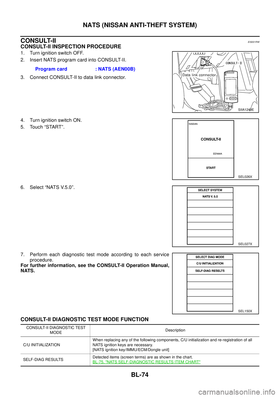
CONSULT-II INSPECTION PROCEDURE
1. Turn ignition switch OFF.
2. Insert NATS program card into CONSULT-II.
3. Connect CONSULT-II to data link connector.
4. Turn ignition switch ON.
5. Touch “START”.
6. Select “NATS V.5.0”.
7. Perform each diagnostic test mode according to each service
procedure.
For further information, see the CONSULT-II Operation Manual,
NATS.
CONSULT-II DIAGNOSTIC TEST MODE FUNCTION
Program card : NATS (AEN00B)
SIIA1249E
SEL026X
SEL027X
SEL150X
CONSULT-II DIAGNOSTIC TEST
MODEDescription
C/U INITIALIZATIONWhen replacing any of the following components, C/U initialization and re-registration of all
NATS ignition keys are necessary.
[NATS ignition key/IMMU/ECM/Dongle unit]
SELF-DIAG RESULTSDetected items (screen terms) are as shown in the chart.
BL-75, "
NATS SELF-DIAGNOSTIC RESULTS ITEM CHART"