CKP Sensor NISSAN X-TRAIL 2003 Electronic Repair Manual
[x] Cancel search | Manufacturer: NISSAN, Model Year: 2003, Model line: X-TRAIL, Model: NISSAN X-TRAIL 2003Pages: 3066, PDF Size: 51.47 MB
Page 761 of 3066
POWERDOORLOCKSYSTEM
BL-17
C
D
E
F
G
H
J
K
L
MA
B
BL
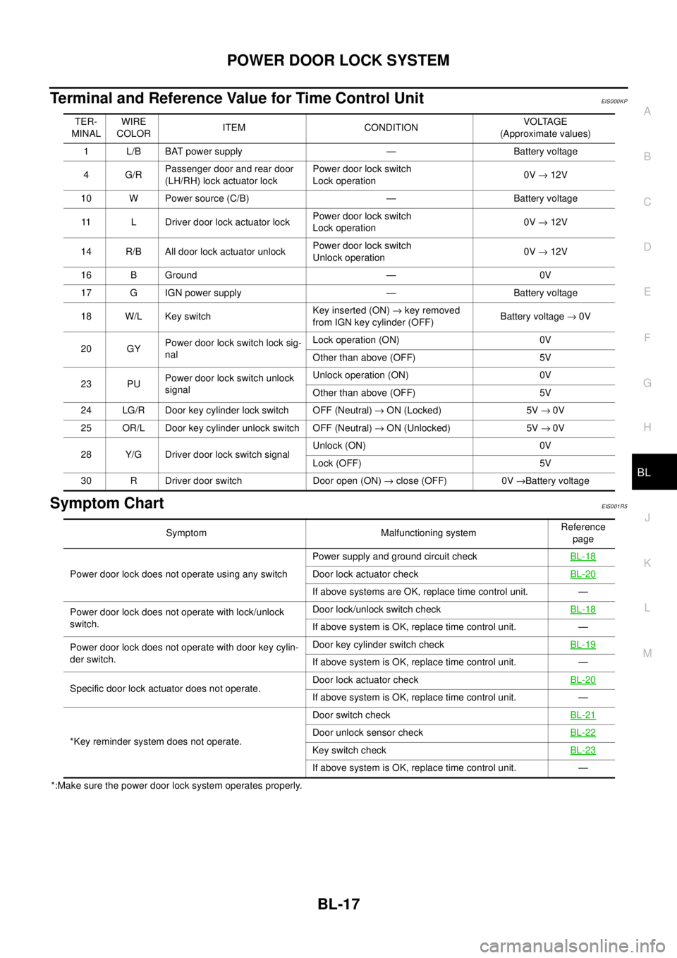
Terminal and Reference Value for Time Control UnitEIS000KP
Symptom ChartEIS001R5
*:Make sure the power door lock system operates properly.TER-
MINALWIRE
COLORITEM CONDITIONVOLTAGE
(Approximate values)
1 L/B BAT power supply — Battery voltage
4G/RPassenger door and rear door
(LH/RH) lock actuator lockPower door lock switch
Lock operation0V®12V
10 W Power source (C/B) — Battery voltage
11 L Driver door lock actuator lockPower door lock switch
Lock operation0V®12V
14 R/B All door lock actuator unlockPower door lock switch
Unlock operation0V®12V
16 B Ground — 0V
17 G IGN power supply — Battery voltage
18 W/L Key switchKey inserted (ON)®key removed
from IGN key cylinder (OFF)Battery voltage®0V
20 GYPower door lock switch lock sig-
nalLock operation (ON) 0V
Other than above (OFF) 5V
23 PUPower door lock switch unlock
signalUnlock operation (ON) 0V
Other than above (OFF) 5V
24 LG/R Door key cylinder lock switch OFF (Neutral)®ON (Locked) 5V®0V
25 OR/L Door key cylinder unlock switch OFF (Neutral)®ON (Unlocked) 5V®0V
28 Y/G Driver door lock switch signalUnlock (ON) 0V
Lock (OFF) 5V
30 R Driver door switch Door open (ON)®close (OFF) 0V®Battery voltage
Symptom Malfunctioning systemReference
page
Power door lock does not operate using any switchPower supply and ground circuit checkBL-18
Door lock actuator checkBL-20
If above systems are OK, replace time control unit. —
Power door lock does not operate with lock/unlock
switch.Door lock/unlock switch checkBL-18
If above system is OK, replace time control unit. —
Power door lock does not operate with door key cylin-
der switch.Door key cylinder switch checkBL-19
If above system is OK, replace time control unit. —
Specific door lock actuator does not operate.Door lock actuator checkBL-20
If above system is OK, replace time control unit. —
*Key reminder system does not operate.Door switch checkBL-21
Door unlock sensor checkBL-22
Key switch checkBL-23
If above system is OK, replace time control unit. —
Page 1117 of 3066

EC-3
C
D
E
F
G
H
I
J
K
L
M
ECA Wiring Diagram .................................................... 183
Diagnostic Procedure ........................................... 184
Component Inspection ......................................... 185
Removal and Installation ...................................... 186
DTC P0139 HO2S2 ................................................. 187
Component Description ........................................ 187
CONSULT-II Reference Value in Data Monitor Mode
. 187
ECM Terminals and Reference Value .................. 187
On Board Diagnosis Logic ................................... 187
DTC Confirmation Procedure ............................... 188
Overall Function Check ........................................ 189
Wiring Diagram .................................................... 190
Diagnostic Procedure ........................................... 191
Component Inspection ......................................... 192
Removal and Installation ...................................... 193
DTC P0171 FUEL INJECTION SYSTEM FUNCTION. 194
On Board Diagnosis Logic ................................... 194
DTC Confirmation Procedure ............................... 194
Wiring Diagram .................................................... 196
Diagnostic Procedure ........................................... 197
DTC P0172 FUEL INJECTION SYSTEM FUNCTION. 200
On Board Diagnosis Logic ................................... 200
DTC Confirmation Procedure ............................... 200
Wiring Diagram .................................................... 202
Diagnostic Procedure ........................................... 203
DTC P0300 - P0304 MULTIPLE CYLINDER MIS-
FIRE, NO. 1 - 4 CYLINDER MISFIRE ..................... 206
On Board Diagnosis Logic ................................... 206
DTC Confirmation Procedure ............................... 206
Diagnostic Procedure ........................................... 207
DTC P0327, P0328 KS ........................................... 212
Component Description ........................................ 212
ECM Terminals and Reference Value .................. 212
On Board Diagnosis Logic ................................... 212
DTC Confirmation Procedure ............................... 212
Wiring Diagram .................................................... 214
Diagnostic Procedure ........................................... 215
Component Inspection ......................................... 216
Removal and Installation ...................................... 216
DTC P0335 CKP SENSOR (POS) .......................... 217
Component Description ........................................ 217
CONSULT-II Reference Value in Data Monitor Mode
. 217
ECM Terminals and Reference Value .................. 217
On Board Diagnosis Logic ................................... 218
DTC Confirmation Procedure ............................... 218
Wiring Diagram .................................................... 219
Diagnostic Procedure ........................................... 220
Component Inspection ......................................... 221
Removal and Installation ...................................... 222
DTC P0340 CMP SENSOR (PHASE) ..................... 223
Component Description ........................................ 223
ECM Terminals and Reference Value .................. 223
On Board Diagnosis Logic ................................... 223
DTC Confirmation Procedure ............................... 224
Wiring Diagram .................................................... 225
Diagnostic Procedure ........................................... 226Component Inspection ..........................................228
Removal and Installation ......................................228
DTC P0420 THREE WAY CATALYST FUNCTION . 229
On Board Diagnosis Logic ....................................229
DTC Confirmation Procedure ...............................229
Overall Function Check ........................................230
Diagnostic Procedure ...........................................231
DTC P0444, P0445 EVAP CANISTER PURGE VOL-
UME CONTROL SOLENOID VALVE ......................233
Description ............................................................233
CONSULT-II Reference Value in Data Monitor Mode
.233
ECM Terminals and Reference Value ...................233
On Board Diagnosis Logic ....................................234
DTC Confirmation Procedure ...............................234
Wiring Diagram .....................................................235
Diagnostic Procedure ...........................................236
Component Inspection ..........................................237
Removal and Installation ......................................238
DTC P0500 VSS ......................................................239
Component Description ........................................239
ECM Terminals and Reference Value ...................239
On Board Diagnosis Logic ....................................239
DTC Confirmation Procedure ...............................239
Overall Function Check ........................................240
Wiring Diagram .....................................................241
Diagnostic Procedure ...........................................243
DTC P0550 PSP SENSOR .....................................244
Component Description ........................................244
CONSULT-II Reference Value in Data Monitor Mode
.244
ECM Terminals and Reference Value ...................244
On Board Diagnosis Logic ....................................244
DTC Confirmation Procedure ...............................244
Wiring Diagram .....................................................246
Diagnostic Procedure ...........................................247
Component Inspection ..........................................248
DTC P0605 ECM .....................................................249
Component Description ........................................249
On Board Diagnosis Logic ....................................249
DTC Confirmation Procedure ...............................249
Diagnostic Procedure ...........................................251
DTC P0650 MI .........................................................252
Component Description ........................................252
On Board Diagnosis Logic ....................................252
DTC Confirmation Procedure ...............................252
Wiring Diagram .....................................................253
Diagnostic Procedure ...........................................254
DTC P1065 ECM POWER SUPPLY .......................256
Component Description ........................................256
On Board Diagnosis Logic ....................................256
DTC Confirmation Procedure ...............................256
Wiring Diagram .....................................................257
Diagnostic Procedure ...........................................258
DTC P1102 MAF SENSOR .....................................260
Component Description ........................................260
CONSULT-II Reference Value in Data Monitor Mode
.260
Page 1120 of 3066

EC-6
DTC Inspection Priority Chart ...............................410
Fail-safe Chart ......................................................411
Basic Inspection ...................................................412
Symptom Matrix Chart ..........................................417
Engine Control Component Parts Location ..........421
Circuit Diagram .....................................................425
ECM Harness Connector Terminal Layout ...........427
ECM Terminals and Reference Value ...................427
CONSULT-II Function ...........................................434
CONSULT-II Reference Value in Data Monitor .....443
Major Sensor Reference Graph in Data Monitor
Mode .....................................................................446
TROUBLE DIAGNOSIS - SPECIFICATION VALUE. 449
Description ............................................................449
Testing Condition ..................................................449
Inspection Procedure ............................................449
Diagnostic Procedure ...........................................450
TROUBLE DIAGNOSIS FOR INTERMITTENT INCI-
DENT .......................................................................453
Description ............................................................453
Diagnostic Procedure ...........................................453
POWER SUPPLY CIRCUIT FOR ECM ...................454
Wiring Diagram .....................................................454
ECM Terminals and Reference Value ...................455
Diagnostic Procedure ...........................................455
Component Inspection ..........................................459
DTC U1000 CAN COMMUNICATION LINE ............460
Description ............................................................460
On Board Diagnosis Logic ....................................460
DTC Confirmation Procedure ...............................460
Wiring Diagram .....................................................461
Diagnostic Procedure ...........................................462
DTC P0102, P0103 MAF SENSOR .........................463
Component Description ........................................463
CONSULT-II Reference Value in Data Monitor Mode
.463
ECM Terminals and Reference Value ...................463
On Board Diagnosis Logic ....................................464
DTC Confirmation Procedure ...............................464
Wiring Diagram .....................................................466
Diagnostic Procedure ...........................................467
Component Inspection ..........................................469
Removal and Installation ......................................469
DTC P0117, P0118 ECT SENSOR ..........................470
Component Description ........................................470
On Board Diagnosis Logic ....................................470
DTC Confirmation Procedure ...............................471
Wiring Diagram .....................................................472
Diagnostic Procedure ...........................................473
Component Inspection ..........................................474
Removal and Installation ......................................474
DTC P0120 TP SENSOR ........................................475
Component Description ........................................475
CONSULT-II Reference Value in Data Monitor Mode
.475
ECM Terminals and Reference Value ...................475
On Board Diagnosis Logic ....................................476
DTC Confirmation Procedure ...............................476Wiring Diagram ..................................................... 479
Diagnostic Procedure ............................................ 480
Component Inspection .......................................... 482
Remove and Installation ....................................... 483
DTC P0121 APP SENSOR ...................................... 484
Component Description ........................................ 484
CONSULT-II Reference Value in Data Monitor Mode
. 484
ECM Terminals and Reference Value ................... 484
On Board Diagnosis Logic .................................... 485
DTC Confirmation Procedure ................................ 485
Wiring Diagram ..................................................... 486
Diagnostic Procedure ............................................ 487
Component Inspection .......................................... 489
Remove and Installation ....................................... 489
DTC P0134 HO2S1 ................................................. 490
Component Description ........................................ 490
CONSULT-II Reference Value in Data Monitor Mode
. 490
ECM Terminals and Reference Value ................... 490
On Board Diagnosis Logic .................................... 491
Overall Function Check ......................................... 491
Wiring Diagram ..................................................... 492
Diagnostic Procedure ............................................ 493
Component Inspection .......................................... 494
Removal and Installation ....................................... 495
DTC P0327, P0328 KS ............................................ 496
Component Description ........................................ 496
ECM Terminals and Reference Value ................... 496
On Board Diagnosis Logic .................................... 496
DTC Confirmation Procedure ................................ 496
Wiring Diagram ..................................................... 498
Diagnostic Procedure ............................................ 499
Component Inspection .......................................... 500
Removal and Installation ....................................... 500
DTC P0335 CKP SENSOR (POS) .......................... 501
Component Description ........................................ 501
CONSULT-II Reference Value in Data Monitor Mode
. 501
ECM Terminals and Reference Value ................... 501
On Board Diagnosis Logic .................................... 502
DTC Confirmation Procedure ................................ 502
Wiring Diagram ..................................................... 503
Diagnostic Procedure ............................................ 504
Component Inspection .......................................... 505
Removal and Installation ....................................... 506
DTC P0340 CMP SENSOR (PHASE) ..................... 507
Component Description ........................................ 507
ECM Terminals and Reference Value ................... 507
On Board Diagnosis Logic .................................... 507
DTC Confirmation Procedure ................................ 508
Wiring Diagram ..................................................... 509
Diagnostic Procedure ............................................ 510
Component Inspection .......................................... 512
Removal and Installation ....................................... 512
DTC P0500 VSS ...................................................... 513
Component Description ........................................ 513
ECM Terminals and Reference Value ................... 513
Page 1233 of 3066
![NISSAN X-TRAIL 2003 Electronic Repair Manual DTC P0011 IVT CONTROL
EC-119
[QR (WITH EURO-OBD)]
C
D
E
F
G
H
I
J
K
L
MA
EC
2. Select "DATA MONITOR" mode with CONSULT-II.
3. Maintain the following conditions for at least 20 consecutive sec-
onds.
4](/img/5/57402/w960_57402-1232.png "NISSAN X-TRAIL 2003 Electronic Repair Manual DTC P0011 IVT CONTROL
EC-119
[QR (WITH EURO-OBD)]
C
D
E
F
G
H
I
J
K
L
MA
EC
2. Select \"DATA MONITOR\" mode with CONSULT-II.
3. Maintain the following conditions for at least 20 consecutive sec-
onds.
4")
DTC P0011 IVT CONTROL
EC-119
[QR (WITH EURO-OBD)]
C
D
E
F
G
H
I
J
K
L
MA
EC
2. Select "DATA MONITOR" mode with CONSULT-II.
3. Maintain the following conditions for at least 20 consecutive sec-
onds.
4. If 1st trip DTC is detected, go toEC-119, "
Diagnostic Procedure"
.
WITH GST
Follow the procedure "With CONSULT-II" above.
Diagnostic ProcedureEBS00B23
1.CHECK CRANKSHAFT POSITION SENSOR (POS)
Refer toEC-221, "
Component Inspection".
OK or NG
OK >> GO TO 2.
NG >> Replace crankshaft position sensor (POS).
2.CHECK CAMSHAFT POSITION SENSOR (PHASE)
Refer toEC-228, "
Component Inspection".
OK or NG
OK >> GO TO 3.
NG >> Replace camshaft position sensor (PHASE).
3.CHECK CAMSHAFT (INTAKE)
Check the following.
lAccumulation of debris to the signal plate of camshaft rear end
lChipping signal plate of camshaft rear end
OK or NG
OK >> GO TO 4.
NG >> Remove debris and clean the signal plate of camshaft
rear end or replace camshaft.
4.CHECK INTERMITTENT INCIDENT
Refer toEC-107, "
TROUBLE DIAGNOSIS FOR INTERMITTENT INCIDENT".
For wiring diagram refer to CKP sensor (POS)EC-219
and CMP sensor (PHASE)EC-225.
>>INSPECTION END
ENG SPEED 2,000 - 3,175 rpm (A constant rotation is maintained.)
COOLANT TEMPS 80 - 90°C (176 - 194°F)
Selector lever 1st or 2nd position
Driving location uphillDriving vehicle uphill
(Increased engine load will help maintain the driving
conditions required for this test.)
SEF174Y
PBIB0565E
Page 1320 of 3066
![NISSAN X-TRAIL 2003 Electronic Repair Manual EC-206
[QR (WITH EURO-OBD)]
DTC P0300 - P0304 MULTIPLE CYLINDER MISFIRE, NO. 1 - 4 CYLINDER MIS-
FIRE
DTC P0300 - P0304 MULTIPLE CYLINDER MISFIRE, NO. 1 - 4 CYLINDER MIS-
FIRE
PFP:00000
On Board Diagn](/img/5/57402/w960_57402-1319.png "NISSAN X-TRAIL 2003 Electronic Repair Manual EC-206
[QR (WITH EURO-OBD)]
DTC P0300 - P0304 MULTIPLE CYLINDER MISFIRE, NO. 1 - 4 CYLINDER MIS-
FIRE
DTC P0300 - P0304 MULTIPLE CYLINDER MISFIRE, NO. 1 - 4 CYLINDER MIS-
FIRE
PFP:00000
On Board Diagn")
EC-206
[QR (WITH EURO-OBD)]
DTC P0300 - P0304 MULTIPLE CYLINDER MISFIRE, NO. 1 - 4 CYLINDER MIS-
FIRE
DTC P0300 - P0304 MULTIPLE CYLINDER MISFIRE, NO. 1 - 4 CYLINDER MIS-
FIRE
PFP:00000
On Board Diagnosis LogicEBS00B5I
When a misfire occurs, engine speed will fluctuate. If the engine speed fluctuates enough to cause the crank-
shaft position (CKP) sensor (POS) signal to vary, ECM can determine that a misfire is occurring.
The misfire detection logic consists of the following two conditions.
1. One Trip Detection Logic (Three Way Catalyst Damage)
On the first trip that a misfire condition occurs that can damage the three way catalyst (TWC) due to over-
heating, the MI will blink.
When a misfire condition occurs, the ECM monitors the CKP sensor (POS) signal every 200 engine revo-
lutions for a change.
When the misfire condition decreases to a level that will not damage the TWC, the MI will turn off.
If another misfire condition occurs that can damage the TWC on a second trip, the MI will blink.
When the misfire condition decreases to a level that will not damage the TWC, the MI will remain on.
If another misfire condition occurs that can damage the TWC, the MI will begin to blink again.
2. Two Trip Detection Logic (Exhaust quality deterioration)
For misfire conditions that will not damage the TWC (but will affect vehicle emissions), the MI will only light
when the misfire is detected on a second trip. During this condition, the ECM monitors the CKP sensor
signal every 1,000 engine revolutions.
A misfire malfunction can be detected on any one cylinder or on multiple cylinders.
DTC Confirmation ProcedureEBS00B5J
CAUTION:
Always drive vehicle at a safe speed.
NOTE:
If “DTC Confirmation Procedure” has been previously conducted, always turn ignition switch “OFF” and wait at
least 10 seconds before conducting the next test.
WITH CONSULT-II
1. Turn ignition switch “ON”, and select “DATA MONITOR” mode with CONSULT-II.
2. Start engine and warm it up to normal operating temperature.
3. Turn ignition switch “OFF” and wait at least 10 seconds.
Sensor Input Signal to ECM ECM function
Crankshaft position sensor (POS) Engine speed On board diagnosis of misfire
DTC No. Trouble diagnosis name DTC detecting condition Possible cause
P0300
0300Multiple cylinder misfire
detectedMultiple cylinder misfire.
lImproper spark plug
lInsufficient compression
lIncorrect fuel pressure
lThe injector circuit is open or shorted
lFuel injectors
lIntake air leak
lThe ignition signal circuit is open or
shorted
lLack of fuel
lDrive plate or flywheel
lHeated oxygen sensor 1 P0301
0301No.1 cylinder misfire
detectedNo. 1 cylinder misfires.
P0302
0302No. 2 cylinder misfire
detectedNo. 2 cylinder misfires.
P0303
0303No. 3 cylinder misfire
detectedNo. 3 cylinder misfires.
P0304
0304No. 4 cylinder misfire
detectedNo. 4 cylinder misfires.
Page 1331 of 3066
![NISSAN X-TRAIL 2003 Electronic Repair Manual DTC P0335 CKP SENSOR (POS)
EC-217
[QR (WITH EURO-OBD)]
C
D
E
F
G
H
I
J
K
L
MA
EC
DTC P0335 CKP SENSOR (POS)PFP:23731
Component DescriptionEBS00B5T
The crankshaft position sensor (POS) is located on th](/img/5/57402/w960_57402-1330.png "NISSAN X-TRAIL 2003 Electronic Repair Manual DTC P0335 CKP SENSOR (POS)
EC-217
[QR (WITH EURO-OBD)]
C
D
E
F
G
H
I
J
K
L
MA
EC
DTC P0335 CKP SENSOR (POS)PFP:23731
Component DescriptionEBS00B5T
The crankshaft position sensor (POS) is located on th")
DTC P0335 CKP SENSOR (POS)
EC-217
[QR (WITH EURO-OBD)]
C
D
E
F
G
H
I
J
K
L
MA
EC
DTC P0335 CKP SENSOR (POS)PFP:23731
Component DescriptionEBS00B5T
The crankshaft position sensor (POS) is located on the cylinder
block rear housing facing the gear teeth (cogs) of the signal plate at
the end of the crankshaft. It detects the fluctuation of the engine rev-
olution.
The sensor consists of a permanent magnet and Hall IC.
When the engine is running, the high and low parts of the teeth
cause the gap with the sensor change.
The changing gap causes the magnetic field near the sensor to
change.
Due to the changing magnetic field, the voltage from the sensor
changes.
The ECM receives the voltage signal and detects the fluctuation of
the engine revolution.
CONSULT-II Reference Value in Data Monitor ModeEBS00B5U
Specification data are reference values.
ECM Terminals and Reference ValueEBS00B5V
Specification data are reference values and are measured between each terminal and body ground.
CAUTION:
Do not use ECM ground terminals when measuring input/output voltage. Doing so may result in dam-
age to the ECM's transistor. Use a ground other than ECM terminals, such as the ground.
: Average voltage for pulse signal (Actual pulse signal can be confirmed by oscilloscope.)
PBIB0562E
MONITOR ITEM CONDITION SPECIFICATION
ENG SPEED·
lTachometer: Connect
lRun engine and compare tachometer indication with the CONSULT-II
value.Almost the same speed as the
CONSULT-II value.
TER-
MINAL
NO.WIRE
COLORITEM CONDITION DATA (DC Voltage)
71 PU/RCrankshaft position
sensor (POS)[Engineisrunning]
lWarm-up condition
lIdle speedApproximately 3V
[Engineisrunning]
lEngine speed is 2,000 rpmApproximately 3V
PBIB0527E
PBIB0528E
Page 1332 of 3066
![NISSAN X-TRAIL 2003 Electronic Repair Manual EC-218
[QR (WITH EURO-OBD)]
DTC P0335 CKP SENSOR (POS)
On Board Diagnosis Logic
EBS00B5W
DTC Confirmation ProcedureEBS00B5X
NOTE:
If “DTC Confirmation Procedure” has been previously conducted, alw](/img/5/57402/w960_57402-1331.png "NISSAN X-TRAIL 2003 Electronic Repair Manual EC-218
[QR (WITH EURO-OBD)]
DTC P0335 CKP SENSOR (POS)
On Board Diagnosis Logic
EBS00B5W
DTC Confirmation ProcedureEBS00B5X
NOTE:
If “DTC Confirmation Procedure” has been previously conducted, alw")
EC-218
[QR (WITH EURO-OBD)]
DTC P0335 CKP SENSOR (POS)
On Board Diagnosis Logic
EBS00B5W
DTC Confirmation ProcedureEBS00B5X
NOTE:
If “DTC Confirmation Procedure” has been previously conducted, always turn ignition switch “OFF” and wait at
least 10 seconds before conducting the next test.
TESTING CONDITION:
Before performing the following procedure, confirm that battery voltage is more than 10.5V with igni-
tion switch "ON".
WITH CONSULT-II
1. Turn ignition switch “ON” and select “DATA MONITOR” mode
with CONSULT-II.
2. Crank engine for at least 2 seconds and run it for at least 5 sec-
onds at idle speed.
3. If 1st trip DTC is detected, go toEC-220, "
Diagnostic Procedure"
.
WITH GST
Follow the procedure “WITH CONSULT-II” above.
DTC No. Trouble diagnosis name DTC detecting condition Possible cause
P0335
0335Crankshaft position
sensor (POS) circuit
lThe crankshaft position sensor (POS) signal
is not detected by the ECM during the first
few seconds of engine cranking.
lThe proper pulse signal from the crankshaft
position sensor (POS) is not sent to ECM
while the engine is running.
lThe crankshaft position sensor (POS) signal
is not in the normal pattern during engine
running.
lHarness or connectors
(The sensor circuit is open or shorted)
lCrankshaft position sensor (POS)
lSignal plate
SEF058Y
Page 1333 of 3066
![NISSAN X-TRAIL 2003 Electronic Repair Manual DTC P0335 CKP SENSOR (POS)
EC-219
[QR (WITH EURO-OBD)]
C
D
E
F
G
H
I
J
K
L
MA
EC
Wiring DiagramEBS00B5Y
TBWA0065E](/img/5/57402/w960_57402-1332.png "NISSAN X-TRAIL 2003 Electronic Repair Manual DTC P0335 CKP SENSOR (POS)
EC-219
[QR (WITH EURO-OBD)]
C
D
E
F
G
H
I
J
K
L
MA
EC
Wiring DiagramEBS00B5Y
TBWA0065E")
DTC P0335 CKP SENSOR (POS)
EC-219
[QR (WITH EURO-OBD)]
C
D
E
F
G
H
I
J
K
L
MA
EC
Wiring DiagramEBS00B5Y
TBWA0065E
Page 1334 of 3066
![NISSAN X-TRAIL 2003 Electronic Repair Manual EC-220
[QR (WITH EURO-OBD)]
DTC P0335 CKP SENSOR (POS)
Diagnostic Procedure
EBS00B5Z
1.RETIGHTEN GROUND SCREWS
1. Turn ignition switch “OFF”.
2. Loosen and retighten engine ground screws.
>> GO TO](/img/5/57402/w960_57402-1333.png "NISSAN X-TRAIL 2003 Electronic Repair Manual EC-220
[QR (WITH EURO-OBD)]
DTC P0335 CKP SENSOR (POS)
Diagnostic Procedure
EBS00B5Z
1.RETIGHTEN GROUND SCREWS
1. Turn ignition switch “OFF”.
2. Loosen and retighten engine ground screws.
>> GO TO")
EC-220
[QR (WITH EURO-OBD)]
DTC P0335 CKP SENSOR (POS)
Diagnostic Procedure
EBS00B5Z
1.RETIGHTEN GROUND SCREWS
1. Turn ignition switch “OFF”.
2. Loosen and retighten engine ground screws.
>> GO TO 2.
2.CHECK CRANKSHAFT POSITION (CKP) SENSOR (POS) POWER SUPPLY CIRCUIT
1. Disconnect crankshaft position (CKP) sensor (POS) harness connector.
2. Turn ignition switch "ON".
3. Check voltage between CKP sensor (POS) terminal 1 and
ground with CONSULT-II or tester.
4. Also check harness for short to ground and short to power.
OK or NG
OK >> GO TO 4.
NG >> GO TO 3.
3.DETECT MALFUNCTIONING PART
Check the following.
lHarness for open or short between ECM and crankshaft position sensor (POS)
lHarness for open or short between ECM relay and crankshaft position sensor (POS)
>> Repair open circuit or short to ground or short to power in harness or connectors.
PBIB0494E
Voltage: Battery voltage
PBIB0512E
PBIB0664E
Page 1335 of 3066
![NISSAN X-TRAIL 2003 Electronic Repair Manual DTC P0335 CKP SENSOR (POS)
EC-221
[QR (WITH EURO-OBD)]
C
D
E
F
G
H
I
J
K
L
MA
EC
4.CHECK CKP (POS) GROUND CIRCUIT FOR OPEN AND SHORT
1. Turn ignition switch "OFF".
2. Check harness continuity between](/img/5/57402/w960_57402-1334.png "NISSAN X-TRAIL 2003 Electronic Repair Manual DTC P0335 CKP SENSOR (POS)
EC-221
[QR (WITH EURO-OBD)]
C
D
E
F
G
H
I
J
K
L
MA
EC
4.CHECK CKP (POS) GROUND CIRCUIT FOR OPEN AND SHORT
1. Turn ignition switch \"OFF\".
2. Check harness continuity between")
DTC P0335 CKP SENSOR (POS)
EC-221
[QR (WITH EURO-OBD)]
C
D
E
F
G
H
I
J
K
L
MA
EC
4.CHECK CKP (POS) GROUND CIRCUIT FOR OPEN AND SHORT
1. Turn ignition switch "OFF".
2. Check harness continuity between CKP sensor (POS) terminal 3 and engine ground.
Refer to Wiring Diagram.
3. Also check harness for short to ground and short to power.
OK or NG
OK >> GO TO 5.
NG >> Repair open circuit or short to ground or short to power in harness or connectors.
5.CHECK CKP SENSOR (POS) INPUT SIGNAL CIRCUIT FOR OPEN AND SHORT
1. Disconnect ECM harness connector.
2. Check harness continuity between ECM terminal 71 and CKP sensor (POS) terminal 2.
Refer to Wiring Diagram.
3. Also check harness for short to ground and short to power.
OK or NG
OK >> GO TO 6.
NG >> Repair open circuit or short to ground or short to power in harness or connectors.
6.CHECK CRANKSHAFT POSITION SENSOR (POS)
Refer toEC-221, "
Component Inspection".
OK or NG
OK >> GO TO 7.
NG >> Replace crankshaft position sensor (POS).
7.CHECK GEAR TOOTH
Visually check for chipping signal plate gear tooth.
OK or NG
OK >> GO TO 8.
NG >> Replace the signal plate.
8.CHECK INTERMITTENT INCIDENT
Refer toEC-107, "
TROUBLE DIAGNOSIS FOR INTERMITTENT INCIDENT".
>>INSPECTION END
Component InspectionEBS00B60
CRANKSHAFT POSITION SENSOR (POS)
1. Loosen the fixing bolt of the sensor.Continuity should exist.
Continuity should exist.