Check balls NISSAN X-TRAIL 2003 Electronic Repair Manual
[x] Cancel search | Manufacturer: NISSAN, Model Year: 2003, Model line: X-TRAIL, Model: NISSAN X-TRAIL 2003Pages: 3066, PDF Size: 51.47 MB
Page 497 of 3066
![NISSAN X-TRAIL 2003 Electronic Repair Manual REPAIR FOR COMPONENT PARTS
AT-491
[ALL]
D
E
F
G
H
I
J
K
L
MA
B
AT
3. Remove O-rings from solenoid valves and terminal body.
4. Place upper body facedown, and remove boltsb,cand nutf.
5. Remove inter b](/img/5/57402/w960_57402-496.png "NISSAN X-TRAIL 2003 Electronic Repair Manual REPAIR FOR COMPONENT PARTS
AT-491
[ALL]
D
E
F
G
H
I
J
K
L
MA
B
AT
3. Remove O-rings from solenoid valves and terminal body.
4. Place upper body facedown, and remove boltsb,cand nutf.
5. Remove inter b")
REPAIR FOR COMPONENT PARTS
AT-491
[ALL]
D
E
F
G
H
I
J
K
L
MA
B
AT
3. Remove O-rings from solenoid valves and terminal body.
4. Place upper body facedown, and remove boltsb,cand nutf.
5. Remove inter body from lower body.
6. Turn over lower body, and remove accumulator support plate.
7. Remove boltse, separating plate and separating gasket from
lower body.
8. Remove check balls and oil cooler relief valve springs from
lower body.
lBe careful not to lose check balls and oil cooler relief
valve springs.
SCIA0804E
SAT064FA
SAT432D
SAT109D
SAT110DA
Page 498 of 3066
![NISSAN X-TRAIL 2003 Electronic Repair Manual AT-492
[ALL]
REPAIR FOR COMPONENT PARTS
9. Remove inter body from upper body.
10. Check to see that steel balls are properly positioned in inter
body and then remove them.
lBe careful not to lose stee](/img/5/57402/w960_57402-497.png "NISSAN X-TRAIL 2003 Electronic Repair Manual AT-492
[ALL]
REPAIR FOR COMPONENT PARTS
9. Remove inter body from upper body.
10. Check to see that steel balls are properly positioned in inter
body and then remove them.
lBe careful not to lose stee")
AT-492
[ALL]
REPAIR FOR COMPONENT PARTS
9. Remove inter body from upper body.
10. Check to see that steel balls are properly positioned in inter
body and then remove them.
lBe careful not to lose steel balls.
11. Check to see that steel balls are properly positioned in upper
body and then remove them.
lBe careful not to lose steel balls.
INSPECTION
Lower and Upper Bodies
lCheck to see that retainer plates are properly positioned in lower
body.
SAT065F
SAT705J
SAT771J
SAT550G
Page 501 of 3066
![NISSAN X-TRAIL 2003 Electronic Repair Manual REPAIR FOR COMPONENT PARTS
AT-495
[ALL]
D
E
F
G
H
I
J
K
L
MA
B
AT
e. Place lower body as shown in illustration (side of inter body face
up). Install steel balls in their proper positions.
f. Install i](/img/5/57402/w960_57402-500.png "NISSAN X-TRAIL 2003 Electronic Repair Manual REPAIR FOR COMPONENT PARTS
AT-495
[ALL]
D
E
F
G
H
I
J
K
L
MA
B
AT
e. Place lower body as shown in illustration (side of inter body face
up). Install steel balls in their proper positions.
f. Install i")
REPAIR FOR COMPONENT PARTS
AT-495
[ALL]
D
E
F
G
H
I
J
K
L
MA
B
AT
e. Place lower body as shown in illustration (side of inter body face
up). Install steel balls in their proper positions.
f. Install inter body on upper body using reamer boltsfas guides.
lBe careful not to dislocate or drop steel balls.
g. Install check balls and oil cooler relief valve springs in their
proper positions in lower body.
h. Install lower separating gasket, lower inter separating gasket
and lower separating plate in order shown in illustration.
i. Install boltsefrom bottom of lower body. Using boltseas
guides, install separating plate and gaskets as a set.
j. Temporarily install support plates on lower body.
SAT705J
SAT076FA
SAT110DA
BAT002
SAT078FA
Page 511 of 3066
![NISSAN X-TRAIL 2003 Electronic Repair Manual REPAIR FOR COMPONENT PARTS
AT-505
[ALL]
D
E
F
G
H
I
J
K
L
MA
B
AT
6. Remove piston from reverse clutch drum by turning it.
7. Remove D-ring and oil seal from piston.
INSPECTION
Reverse Clutch Snap Rin](/img/5/57402/w960_57402-510.png "NISSAN X-TRAIL 2003 Electronic Repair Manual REPAIR FOR COMPONENT PARTS
AT-505
[ALL]
D
E
F
G
H
I
J
K
L
MA
B
AT
6. Remove piston from reverse clutch drum by turning it.
7. Remove D-ring and oil seal from piston.
INSPECTION
Reverse Clutch Snap Rin")
REPAIR FOR COMPONENT PARTS
AT-505
[ALL]
D
E
F
G
H
I
J
K
L
MA
B
AT
6. Remove piston from reverse clutch drum by turning it.
7. Remove D-ring and oil seal from piston.
INSPECTION
Reverse Clutch Snap Ring, Spring Retainer and Return Springs
lCheck for deformation, fatigue or damage.
If necessary, replace.
Reverse Clutch Drive Plates
lCheck facing for burns, cracks or damage.
lMeasure thickness of facing.
lIf not within wear limit, replace.
Reverse Clutch Dish Plates
lCheck for deformation or damage.
lMeasure thickness of dish plate.
lIf deformed or fatigued, replace.
Reverse Clutch Piston
lMake sure that check balls are not fixed.
lApply compressed air to check ball oil hole opposite the return spring. Make sure there is no air leakage.
lApply compressed air to oil hole on return spring side to make sure that air leaks past ball.
SAT096F
Thickness of drive plate:
Standard value: 1.6 mm (0.063 in)
Wear limit: 1.4 mm (0.055 in)
SAT162D
Thickness of dish plate: 3.08 mm (0.1213 in)
SAT163D
Page 515 of 3066
![NISSAN X-TRAIL 2003 Electronic Repair Manual REPAIR FOR COMPONENT PARTS
AT-509
[ALL]
D
E
F
G
H
I
J
K
L
MA
B
AT
INSPECTION
High Clutch Snap Ring, Spring Retainer and Return Springs
lCheck for deformation, fatigue or damage.
If necessary, replace.](/img/5/57402/w960_57402-514.png "NISSAN X-TRAIL 2003 Electronic Repair Manual REPAIR FOR COMPONENT PARTS
AT-509
[ALL]
D
E
F
G
H
I
J
K
L
MA
B
AT
INSPECTION
High Clutch Snap Ring, Spring Retainer and Return Springs
lCheck for deformation, fatigue or damage.
If necessary, replace.")
REPAIR FOR COMPONENT PARTS
AT-509
[ALL]
D
E
F
G
H
I
J
K
L
MA
B
AT
INSPECTION
High Clutch Snap Ring, Spring Retainer and Return Springs
lCheck for deformation, fatigue or damage.
If necessary, replace.
lWhen replacing spring retainer and return springs, replace them as a set.
High Clutch Drive Plates
lCheck facing for burns, cracks or damage.
lMeasure thickness of facing.
lIf not within wear limit, replace.
High Clutch Piston
lMake sure that check balls are not fixed.
lApply compressed air to check ball oil hole opposite the return
spring. Make sure there is no air leakage.
lApplycompressedairtooilholeonreturnspringsidetomake
sure that air leaks past ball.
Seal Ring Clearance
lInstall new seal rings onto input shaft.
lMeasure clearance between seal ring and ring groove.
lIf not within allowable limit, replace input shaft assembly.
ASSEMBLY
1. Install D-rings on piston.
lApply ATF to both parts. Thickness of drive plate:
Standard value 1.6 mm (0.063 in)
Wear limit 1.4 mm (0.055 in)
SAT162D
SAT186D
Standard clearance: 0.08 - 0.23 mm (0.0031 - 0.0091 in)
Allowable limit: 0.23 mm (0.0091 in)
SAT187D
SAT371FA
Page 520 of 3066
![NISSAN X-TRAIL 2003 Electronic Repair Manual AT-514
[ALL]
REPAIR FOR COMPONENT PARTS
10. Remove D-rings and oil seals from forward clutch piston and
overrun clutch piston.
INSPECTION
Snap Rings, Spring Retainer and Return Springs
lCheck for defo](/img/5/57402/w960_57402-519.png "NISSAN X-TRAIL 2003 Electronic Repair Manual AT-514
[ALL]
REPAIR FOR COMPONENT PARTS
10. Remove D-rings and oil seals from forward clutch piston and
overrun clutch piston.
INSPECTION
Snap Rings, Spring Retainer and Return Springs
lCheck for defo")
AT-514
[ALL]
REPAIR FOR COMPONENT PARTS
10. Remove D-rings and oil seals from forward clutch piston and
overrun clutch piston.
INSPECTION
Snap Rings, Spring Retainer and Return Springs
lCheck for deformation, fatigue or damage.
lReplace if necessary.
lWhen replacing spring retainer and return springs, replace them as a set.
Forward Clutch and Overrun Clutch Drive Plates
lCheck facing for burns, cracks or damage.
lMeasure thickness of facing.
lIf not within wear limit, replace.
ForwardClutch andOverrunClutchDishPlates
lCheck for deformation or damage.
lMeasure thickness of dish plate.
lIf deformed or fatigued, replace.
Forward Clutch Drum
lMake sure that check balls are not fixed.
lApply compressed air to check ball oil hole from outside of for-
ward clutch drum. Make sure air leaks past ball.
lApply compressed air to oil hole from inside of forward clutch
drum. Make sure there is no air leakage.
SAT127FB
Thickness of drive plate:
Forward clutch
Standard value: 1.6 mm (0.063 in)
Wear limit: 1.4 mm (0.055 in)
Overrun clutch
Standard value: 1.6 mm (0.063 in)
Wear limit: 1.6 mm (0.063 in)
SAT162D
Thickness of dish plate:
Forward clutch 2.7 mm (0.106 in)
Overrun clutch 2.7 mm (0.106 in)
SAT163D
SAT213D
Page 521 of 3066
![NISSAN X-TRAIL 2003 Electronic Repair Manual REPAIR FOR COMPONENT PARTS
AT-515
[ALL]
D
E
F
G
H
I
J
K
L
MA
B
AT
OverrunClutchPiston
lMake sure that check balls are not fixed.
lApply compressed air to check ball oil hole opposite the return
spring](/img/5/57402/w960_57402-520.png "NISSAN X-TRAIL 2003 Electronic Repair Manual REPAIR FOR COMPONENT PARTS
AT-515
[ALL]
D
E
F
G
H
I
J
K
L
MA
B
AT
OverrunClutchPiston
lMake sure that check balls are not fixed.
lApply compressed air to check ball oil hole opposite the return
spring")
REPAIR FOR COMPONENT PARTS
AT-515
[ALL]
D
E
F
G
H
I
J
K
L
MA
B
AT
OverrunClutchPiston
lMake sure that check balls are not fixed.
lApply compressed air to check ball oil hole opposite the return
spring. Make sure there is no air leakage.
lApply compressed air to oil hole on return spring side. Make
sure that air leaks past ball.
ASSEMBLY
1. Install D-rings and oil seals on forward clutch piston and overrun
clutch piston.
lTake care with direction of oil seal.
lApply ATF to both parts.
2. Install overrun clutch piston assembly on forward clutch piston
by turning it slowly.
lApply ATF to inner surface of forward clutch piston.
3. Install forward clutch piston assembly on forward clutch drum by
turning it slowly.
lApply ATF to inner surface of drum.
SAT212D
SAT127FB
SAT126F
SAT125F
Page 2564 of 3066
MT-28
TRANSAXLE ASSEMBLY
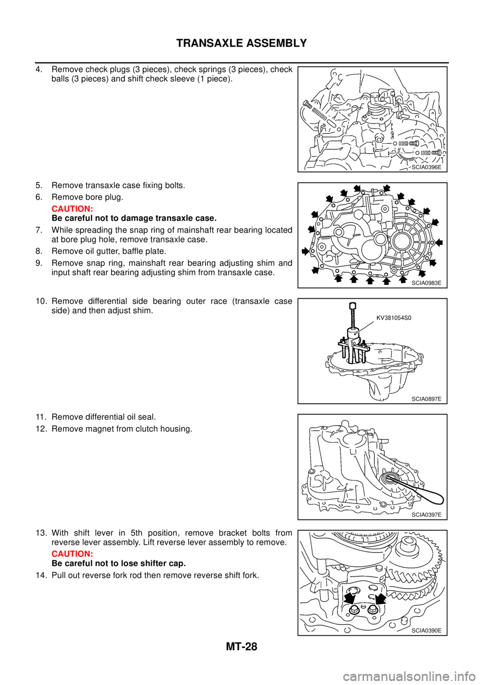
4. Remove check plugs (3 pieces), check springs (3 pieces), check
balls (3 pieces) and shift check sleeve (1 piece).
5. Remove transaxle case fixing bolts.
6. Remove bore plug.
CAUTION:
Be careful not to damage transaxle case.
7. While spreading the snap ring of mainshaft rear bearing located
at bore plug hole, remove transaxle case.
8. Remove oil gutter, baffle plate.
9. Remove snap ring, mainshaft rear bearing adjusting shim and
input shaft rear bearing adjusting shim from transaxle case.
10. Remove differential side bearing outer race (transaxle case
side) and then adjust shim.
11. Remove differential oil seal.
12. Remove magnet from clutch housing.
13. With shift lever in 5th position, remove bracket bolts from
reverse lever assembly. Lift reverse lever assembly to remove.
CAUTION:
Be careful not to lose shifter cap.
14. Pull out reverse fork rod then remove reverse shift fork.
SCIA0396E
SCIA0983E
SCIA0897E
SCIA0397E
SCIA0390E
Page 2565 of 3066
TRANSAXLE ASSEMBLY
MT-29
D
E
F
G
H
I
J
K
L
MA
B
MT
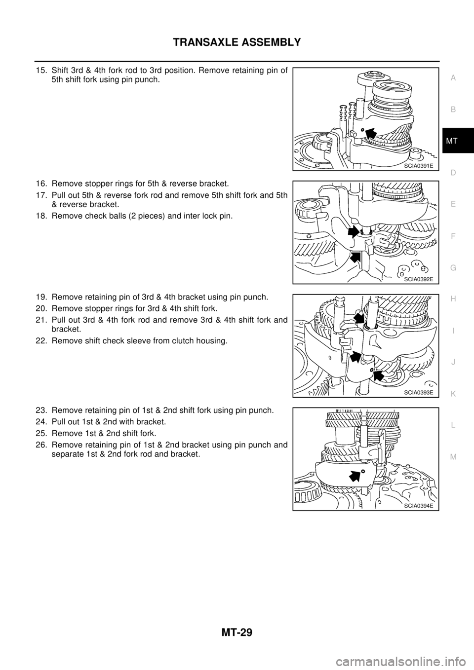
15. Shift 3rd & 4th fork rod to 3rd position. Remove retaining pin of
5th shift fork using pin punch.
16. Remove stopper rings for 5th & reverse bracket.
17. Pull out 5th & reverse fork rod and remove 5th shift fork and 5th
& reverse bracket.
18. Remove check balls (2 pieces) and inter lock pin.
19. Remove retaining pin of 3rd & 4th bracket using pin punch.
20. Remove stopper rings for 3rd & 4th shift fork.
21. Pull out 3rd & 4th fork rod and remove 3rd & 4th shift fork and
bracket.
22. Remove shift check sleeve from clutch housing.
23. Remove retaining pin of 1st & 2nd shift fork using pin punch.
24. Pull out 1st & 2nd with bracket.
25. Remove 1st & 2nd shift fork.
26. Remove retaining pin of 1st & 2nd bracket using pin punch and
separate 1st & 2nd fork rod and bracket.
SCIA0391E
SCIA0392E
SCIA0393E
SCIA0394E
Page 2569 of 3066
TRANSAXLE ASSEMBLY
MT-33
D
E
F
G
H
I
J
K
L
MA
B
MT
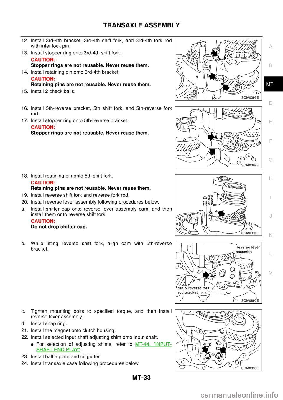
12. Install 3rd-4th bracket, 3rd-4th shift fork, and 3rd-4th fork rod
with inter lock pin.
13. Install stopper ring onto 3rd-4th shift fork.
CAUTION:
Stopper rings are not reusable. Never reuse them.
14. Install retaining pin onto 3rd-4th bracket.
CAUTION:
Retaining pins are not reusable. Never reuse them.
15. Install 2 check balls.
16. Install 5th-reverse bracket, 5th shift fork, and 5th-reverse fork
rod.
17. Install stopper ring onto 5th-reverse bracket.
CAUTION:
Stopper rings are not reusable. Never reuse them.
18. Install retaining pin onto 5th shift fork.
CAUTION:
Retaining pins are not reusable. Never reuse them.
19. Install reverse shift fork and reverse fork rod.
20. Install reverse lever assembly following procedures below.
a. Install shifter cap onto reverse lever assembly cam, and then
install them onto reverse shift fork.
CAUTION:
Do not drop shifter cap.
b. While lifting reverse shift fork, align cam with 5th-reverse
bracket.
c. Tighten mounting bolts to specified torque, and then install
reverse lever assembly.
d. Install snap ring.
21. Install the magnet onto clutch housing.
22. Install selected input shaft adjusting shim onto input shaft.
lFor selection of adjusting shims, refer toMT-44, "INPUT-
SHAFT END PLAY".
23. Install baffle plate and oil gutter.
24. Install transaxle case following procedures below.
SCIA0393E
SCIA0392E
SCIA0391E
SCIA0890E
SCIA0390E