key battery NISSAN X-TRAIL 2003 Electronic Repair Manual
[x] Cancel search | Manufacturer: NISSAN, Model Year: 2003, Model line: X-TRAIL, Model: NISSAN X-TRAIL 2003Pages: 3066, PDF Size: 51.47 MB
Page 454 of 3066
![NISSAN X-TRAIL 2003 Electronic Repair Manual AT-448
[ALL]
A/T SHIFT LOCK SYSTEM
Diagnostic Procedure
ECS00408
SYMPTOM 1:
lSelector lever cannot be moved from “P” position with key in ON position and brake pedal
applied.
lSelector lever can b NISSAN X-TRAIL 2003 Electronic Repair Manual AT-448
[ALL]
A/T SHIFT LOCK SYSTEM
Diagnostic Procedure
ECS00408
SYMPTOM 1:
lSelector lever cannot be moved from “P” position with key in ON position and brake pedal
applied.
lSelector lever can b](/img/5/57402/w960_57402-453.png)
AT-448
[ALL]
A/T SHIFT LOCK SYSTEM
Diagnostic Procedure
ECS00408
SYMPTOM 1:
lSelector lever cannot be moved from “P” position with key in ON position and brake pedal
applied.
lSelector lever can be moved from “P” position with key in ON position and brake pedal released.
lSelector lever can be moved from “P” position when key is removed from key cylinder.
SYMPTOM 2:
Ignition key cannot be removed when selector lever is set to “P” position. It can be removed when
selector lever is set to any position except “P”.
1.CHECKKEYINTERLOCKCABLE
Check key interlock cable for damage.
OK or NG
OK >> GO TO 2
NG >> Repair key interlock cable. Refer toAT - 4 5 2 , "
KEY INTERLOCK CABLE".
2.CHECK SELECTOR LEVER POSITION
Check selector lever position for damage.
OK or NG
OK >> GO TO 3
NG >> Check selector lever. Refer toAT - 4 5 6 , "
Park/Neutral Position (PNP) Switch Adjustment".
3.CHECK POWER SOURCE
1. Turn ignition switch to “ON” position.
(Do not start engine.)
2. Check voltage between stop lamp switch harness terminal 1 and ground.
OK or NG
OK >> GO TO 4
NG >> Check the following items:
1. Harness for short or open between battery and stop
lamp switch harness terminal 1
2. Fuse
3. Ignition switch (Refer toPG-2, "
POWER SUPPLY
ROUTING".) Voltage : Battery voltageSCIA0782E
Page 726 of 3066

AV-4
AUDIO
Service Procedure
SPEED DEPENDENT VOLUME CONTROL
Description
If activated, the radio output volume will be automatically adjusted to compensate for increased driving noises
at higher driving speeds.
The radio receives a speed signal from the vehicle speed sensor (VSS) and selects the output volume.
PERSONAL AUDIO SETTINGS
Description
The radio is designed to store several settings (volume, bass, treble, preset stations and level of speed depen-
dent volume control) with every NATS ignition key used. Up to a maximum of 4 NATS keys can be registered.
During the communication mentioned under “Anti-Theft System”, the radio will recognize the used ignition key
and select the accompanying settings.
Item Service procedure Description
Battery disconnection No additional action required. —
Radio needs repair Repair needs to be done by authorized
representative of radio manufacturer since
radio cannot be operated unless it is reset
to NEW state, using special decoding
equipment.—
Replacement of radio by new part No additional action required. Radio is delivered in NEW state.
Transferring radio to another vehicle/
replacement of radio by an “old” partRadio needs to be reset to NEW state by
authorized representative of radio manu-
facturer.—
Replacement of IMMU Radio needs to be reset to NEW state by
authorized representative of Clarion.After switching on the radio, it will display
“SECURE” after 1 minute.
No communication from IMMU to radio 1. If NATS is malfunctioning, check NATS
system.
2. After NATS is repaired, reset radio to
NEW state by authorized representative
of Clarion.After switching on the radio, the radio will
display “SECURE” after 1 minute. Further
use of radio is impossible until communica-
tion is established again, or after radio is
reset by authorized representative of Clar-
ion.
When initialized between ECM and IMMU. Radio needs to be reset to NEW status by
authorized representative of Clarion.After switching on the radio, it will display
“SECURE” after 1 minute.
Page 745 of 3066

BL-1
BODY, LOCK & SECURITY SYSTEM
IBODY
CONTENTS
C
D
E
F
G
H
J
K
L
M
SECTION
A
B
BL
BODY, LOCK & SECURITY SYSTEM
PRECAUTIONS .......................................................... 3
Precautions .............................................................. 3
HOOD ......................................................................... 4
Fitting Adjustment .................................................... 4
FRONT END HEIGHT ADJUSTMENT AND LAT-
ERAL/LONGITUDIAL CLEARANCE ADJUST-
MENT .................................................................... 4
SURFACE HEIGHT ADJUSTMENT ..................... 4
Removal and Installation of Hood Assembly ............ 5
Removal and Installation of Hood Lock Control ....... 6
REMOVAL ............................................................. 6
INSTALLATION ..................................................... 7
Hood Lock Control Inspection .................................. 7
DOOR ......................................................................... 8
Fitting Adjustment .................................................... 8
FRONT DOOR ...................................................... 8
REAR DOOR ........................................................ 8
STRIKER ADJUSTMENT ..................................... 9
Removal and Installation .......................................... 9
Door Weatherstrip .................................................. 10
POWER DOOR LOCK SYSTEM ...............................11
System Description .................................................11
OPERATION ........................................................11
Component Parts and Harness Connector Location....11
Schematic .............................................................. 12
Wiring Diagram — D/LOCK — ............................... 13
Terminal and Reference Value for Time Control Unit... 17
Symptom Chart ...................................................... 17
Power Supply and Ground Circuit Check ............... 18
Door Lock/Unlock Switch Check ............................ 18
Door Key Cylinder Switch Check ........................... 19
Door Lock Actuator Check ..................................... 20
Door Switch Check ................................................. 21
Door Unlock Sensor Check .................................... 22
Key Switch Check .................................................. 23
POWER DOOR LOCK — SUPER LOCK — ............ 24
System Description ................................................ 24
OUTLINE ............................................................. 24
OPERATION ....................................................... 24
Schematic .............................................................. 26Wiring Diagram — S/LOCK — ............................... 27
Terminal and Reference Value for Time Control Unit... 33
Trouble Diagnoses ................................................. 34
PRELIMINARY CHECK ....................................... 34
SYMPTOM CHART ............................................. 35
Power Supply and Ground Circuit Check ............... 36
Door Lock/Unlock Switch Check ............................ 36
Door Key Cylinder Switch Check ............................ 37
Door Lock Actuator Check ...................................... 38
Door Switch Check ................................................. 39
Door Unlock Sensor Check .................................... 40
Key Switch Check ................................................... 41
Super Lock Actuator Check .................................... 42
NATS Release Signal Check .................................. 43
Ignition Switch “ON” Circuit Check ......................... 44
Remote Controller Signal Check ............................ 44
MULTI-REMOTE CONTROL SYSTEM ..................... 45
Component Parts and Harness Connector Location... 45
System Description ................................................. 45
FUNCTION .......................................................... 45
LOCK OPERATION ............................................. 45
UNLOCK OPERATION ........................................ 46
HAZARD REMINDER ......................................... 46
MULTI-REMOTE CONTROLLER ID CODE
ENTRY ................................................................ 46
Wiring Diagram — MULTI — .................................. 47
Terminal and Reference Value for Multi-remote
Control Unit ............................................................. 49
Symptom Chart ....................................................... 49
Remote Controller Battery Check ........................... 49
Power Supply and Ground Circuit Check ............... 50
Hazard Reminder Check ........................................ 51
ID Code Entry Procedure ....................................... 52
Remote Controller Battery Replacement ................ 53
FRONT DOOR LOCK ............................................... 54
Component Parts Location ..................................... 54
Inspection and Adjustment ..................................... 54
OUT SIDE HANDLE ROD ADJUSTMENT .......... 54
Removal and Installation ........................................ 54
REMOVAL ........................................................... 54
Page 761 of 3066
POWERDOORLOCKSYSTEM
BL-17
C
D
E
F
G
H
J
K
L
MA
B
BL
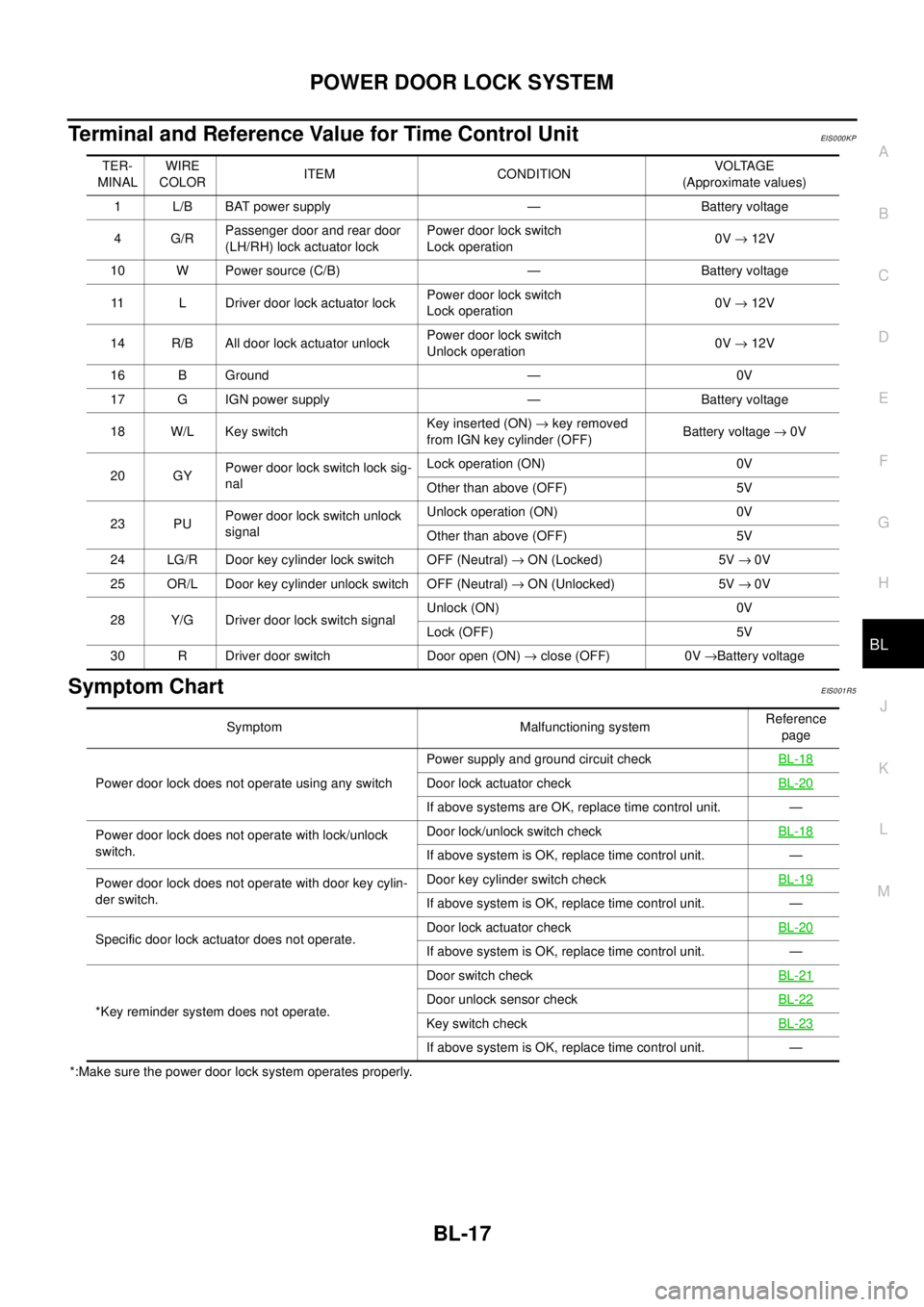
Terminal and Reference Value for Time Control UnitEIS000KP
Symptom ChartEIS001R5
*:Make sure the power door lock system operates properly.TER-
MINALWIRE
COLORITEM CONDITIONVOLTAGE
(Approximate values)
1 L/B BAT power supply — Battery voltage
4G/RPassenger door and rear door
(LH/RH) lock actuator lockPower door lock switch
Lock operation0V®12V
10 W Power source (C/B) — Battery voltage
11 L Driver door lock actuator lockPower door lock switch
Lock operation0V®12V
14 R/B All door lock actuator unlockPower door lock switch
Unlock operation0V®12V
16 B Ground — 0V
17 G IGN power supply — Battery voltage
18 W/L Key switchKey inserted (ON)®key removed
from IGN key cylinder (OFF)Battery voltage®0V
20 GYPower door lock switch lock sig-
nalLock operation (ON) 0V
Other than above (OFF) 5V
23 PUPower door lock switch unlock
signalUnlock operation (ON) 0V
Other than above (OFF) 5V
24 LG/R Door key cylinder lock switch OFF (Neutral)®ON (Locked) 5V®0V
25 OR/L Door key cylinder unlock switch OFF (Neutral)®ON (Unlocked) 5V®0V
28 Y/G Driver door lock switch signalUnlock (ON) 0V
Lock (OFF) 5V
30 R Driver door switch Door open (ON)®close (OFF) 0V®Battery voltage
Symptom Malfunctioning systemReference
page
Power door lock does not operate using any switchPower supply and ground circuit checkBL-18
Door lock actuator checkBL-20
If above systems are OK, replace time control unit. —
Power door lock does not operate with lock/unlock
switch.Door lock/unlock switch checkBL-18
If above system is OK, replace time control unit. —
Power door lock does not operate with door key cylin-
der switch.Door key cylinder switch checkBL-19
If above system is OK, replace time control unit. —
Specific door lock actuator does not operate.Door lock actuator checkBL-20
If above system is OK, replace time control unit. —
*Key reminder system does not operate.Door switch checkBL-21
Door unlock sensor checkBL-22
Key switch checkBL-23
If above system is OK, replace time control unit. —
Page 769 of 3066

POWER DOOR LOCK — SUPER LOCK —
BL-25
C
D
E
F
G
H
J
K
L
MA
B
BL
Lock/unlock switch operation cannot control super lock
Key reminder system
lIf the ignition key is in the ignition key cylinder and driver door is open, setting lock/unlock switch, lock
knob, key or multi-remote controller to “LOCK” locks the door once but then immediately unlocks all doors.
(signal from door unlock sensor driver side)
System initialization
lSystem initialization is required when battery cables are reconnected. Conduct the following to release
super lock once;
–insert the key into the ignition key cylinder and turn it to ON.
–LOCK/UNLOCK operation using door key cylinder or multi-remote controller.
Page 777 of 3066

POWER DOOR LOCK — SUPER LOCK —
BL-33
C
D
E
F
G
H
J
K
L
MA
B
BL
Terminal and Reference Value for Time Control UnitEIS001SR
TER-
MINALWIRE
COLORITEM CONDITIONVOLTAGE
(Approximate values)
1 L/B BAT power supply — Battery voltage
3 L/Y Super lock actuator releaseDoor key cylinder switch
Unlock operation (Released)0V®12V
4G/RPassenger door and rear door
(LH/RH) lock actuator unlockPower door lock switch
Unlock operation0V®12V
6 Y/R Super lock actuator setDoor key cylinder switch
Lock operation (Set)0V®12V
10 W Power source (C/B) — Battery voltage
11 L Driver door lock actuator unlockPower door lock switch
Unlock operation0V®12V
14 R/B All door lock actuator lockPower door lock switch
Lock operation0V®12V
16 B Ground — 0V
17 G IGN power supply — Battery voltage
18 W/L Key switchKey inserted (ON)®key removed
from IGN key cylinder (OFF)Battery voltage®0V
20 GYPower door lock switch lock sig-
nalLock operation (ON) 0V
Other than above (OFF) 5V
23 PUPower door lock switch unlock
signalUnlock operation (ON) 0V
Other than above (OFF) 5V
24 LG/R Door key cylinder lock switch OFF (Neutral)®ON (Locked) 5V®0V
25 OR/L Door key cylinder unlock switch OFF (Neutral)®ON (Unlocked) 5V®0V
28 Y/G Driver door lock switch signalUnlock (ON) 0V
Lock (OFF) 5V
29 Y/LPassenger door lock switch sig-
nalUnlock (ON) 0V
Lock (OFF) 5V
30 R Driver door switch Door open (ON)®close (OFF) 0V®Battery voltage
32 OR Key less lock signalRemote controller button
Lock pressed5V®0V (Approx. 0.5 sec-
onds)
33 P/L Key less unlock signalRemote controller button
Unlock pressed5V®0V (Approx. 0.5 sec-
onds)
34 B/Y NATS release signal — 5V
Page 788 of 3066
BL-44
POWER DOOR LOCK — SUPER LOCK —
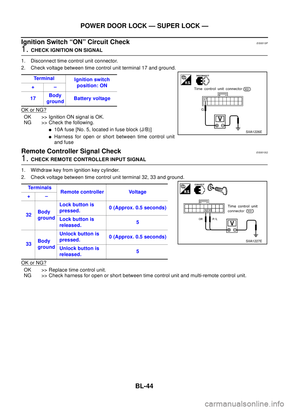
Ignition Switch “ON” Circuit Check
EIS001SP
1.CHECK IGNITION ON SIGNAL
1. Disconnect time control unit connector.
2. Check voltage between time control unit terminal 17 and ground.
OK or NG?
OK >> Ignition ON signal is OK.
NG >> Check the following.
l10A fuse [No. 5, located in fuse block (J/B)]
lHarness for open or short between time control unit
and fuse
Remote Controller Signal CheckEIS001SQ
1.CHECK REMOTE CONTROLLER INPUT SIGNAL
1. Withdraw key from ignition key cylinder.
2. Check voltage between time control unit terminal 32, 33 and ground.
OK or NG?
OK >> Replace time control unit.
NG >> Check harness for open or short between time control unit and multi-remote control unit.Te r m i n a l
Ignition switch
position: ON
+–
17Body
groundBattery voltage
SIIA1226E
Te r m i n a l s
Remote controller Voltage
+–
32Body
groundLock button is
pressed.0 (Approx. 0.5 seconds)
Lock button is
released.5
33Body
groundUnlock button is
pressed.0 (Approx. 0.5 seconds)
Unlock button is
released.5
SIIA1227E
Page 793 of 3066
MULTI-REMOTE CONTROL SYSTEM
BL-49
C
D
E
F
G
H
J
K
L
MA
B
BL
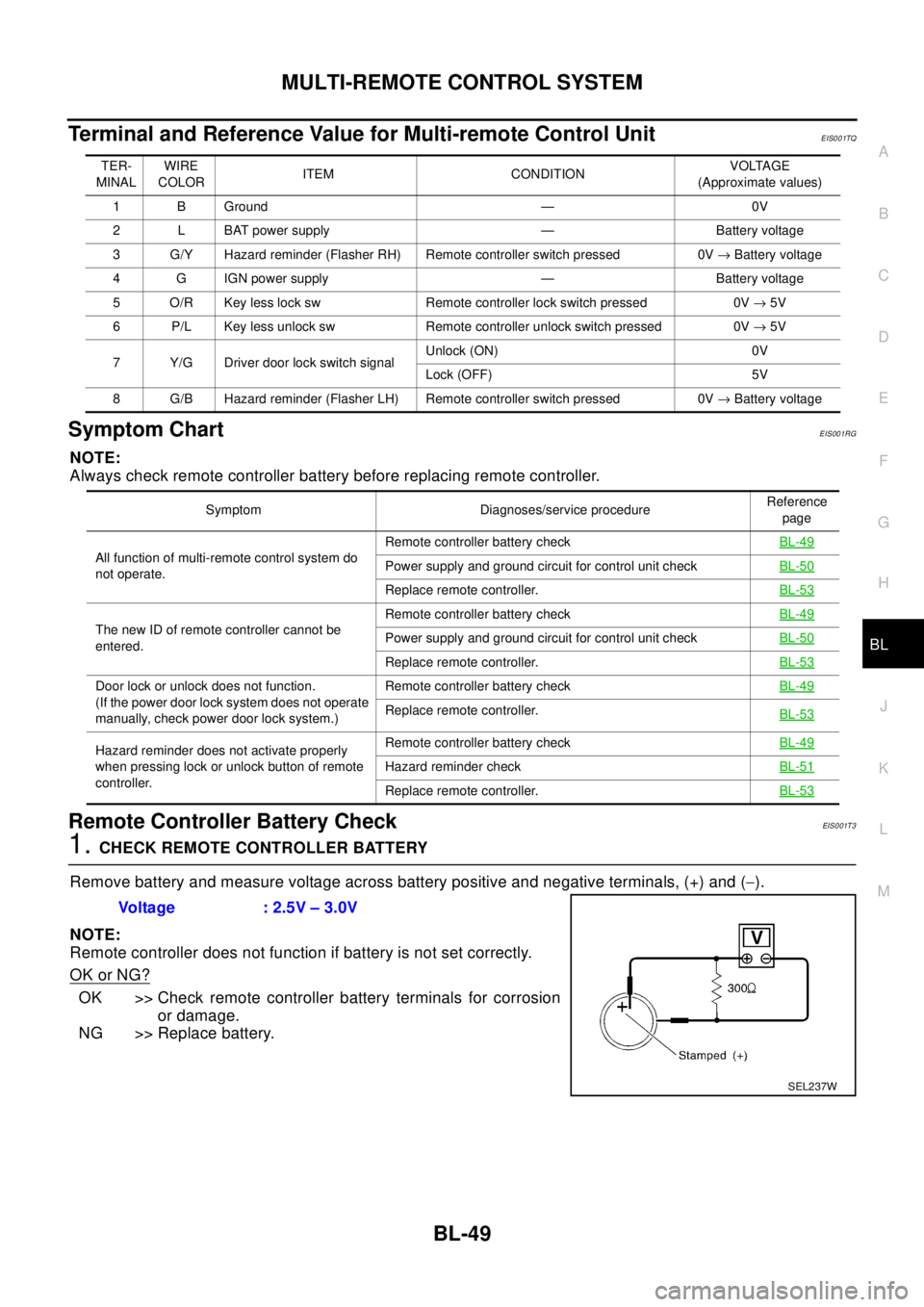
Terminal and Reference Value for Multi-remote Control UnitEIS001TQ
Symptom ChartEIS001RG
NOTE:
Always check remote controller battery before replacing remote controller.
Remote Controller Battery CheckEIS0 01T 3
1.CHECK REMOTE CONTROLLER BATTERY
Remove battery and measure voltage across battery positive and negative terminals, (+) and (-).
NOTE:
Remote controller does not function if battery is not set correctly.
OK or NG?
OK >> Check remote controller battery terminals for corrosion
or damage.
NG >> Replace battery.
TER-
MINALWIRE
COLORITEM CONDITIONVOLTAGE
(Approximate values)
1 B Ground — 0V
2 L BAT power supply — Battery voltage
3 G/Y Hazard reminder (Flasher RH) Remote controller switch pressed 0V®Battery voltage
4 G IGN power supply — Battery voltage
5 O/R Key less lock sw Remote controller lock switch pressed 0V®5V
6 P/L Key less unlock sw Remote controller unlock switch pressed 0V®5V
7 Y/G Driver door lock switch signalUnlock (ON) 0V
Lock (OFF) 5V
8 G/B Hazard reminder (Flasher LH) Remote controller switch pressed 0V®Battery voltage
Symptom Diagnoses/service procedureReference
page
All function of multi-remote control system do
not operate.Remote controller battery checkBL-49
Power supply and ground circuit for control unit checkBL-50
Replace remote controller.BL-53
The new ID of remote controller cannot be
entered.Remote controller battery checkBL-49Power supply and ground circuit for control unit checkBL-50
Replace remote controller.BL-53
Door lock or unlock does not function.
(If the power door lock system does not operate
manually, check power door lock system.)Remote controller battery checkBL-49
Replace remote controller.
BL-53
Hazard reminder does not activate properly
when pressing lock or unlock button of remote
controller.Remote controller battery checkBL-49
Hazard reminder checkBL-51
Replace remote controller.BL-53
Voltage : 2.5V – 3.0V
SEL237W
Page 822 of 3066
BL-78
NATS (NISSAN ANTI-THEFT SYSTEM)
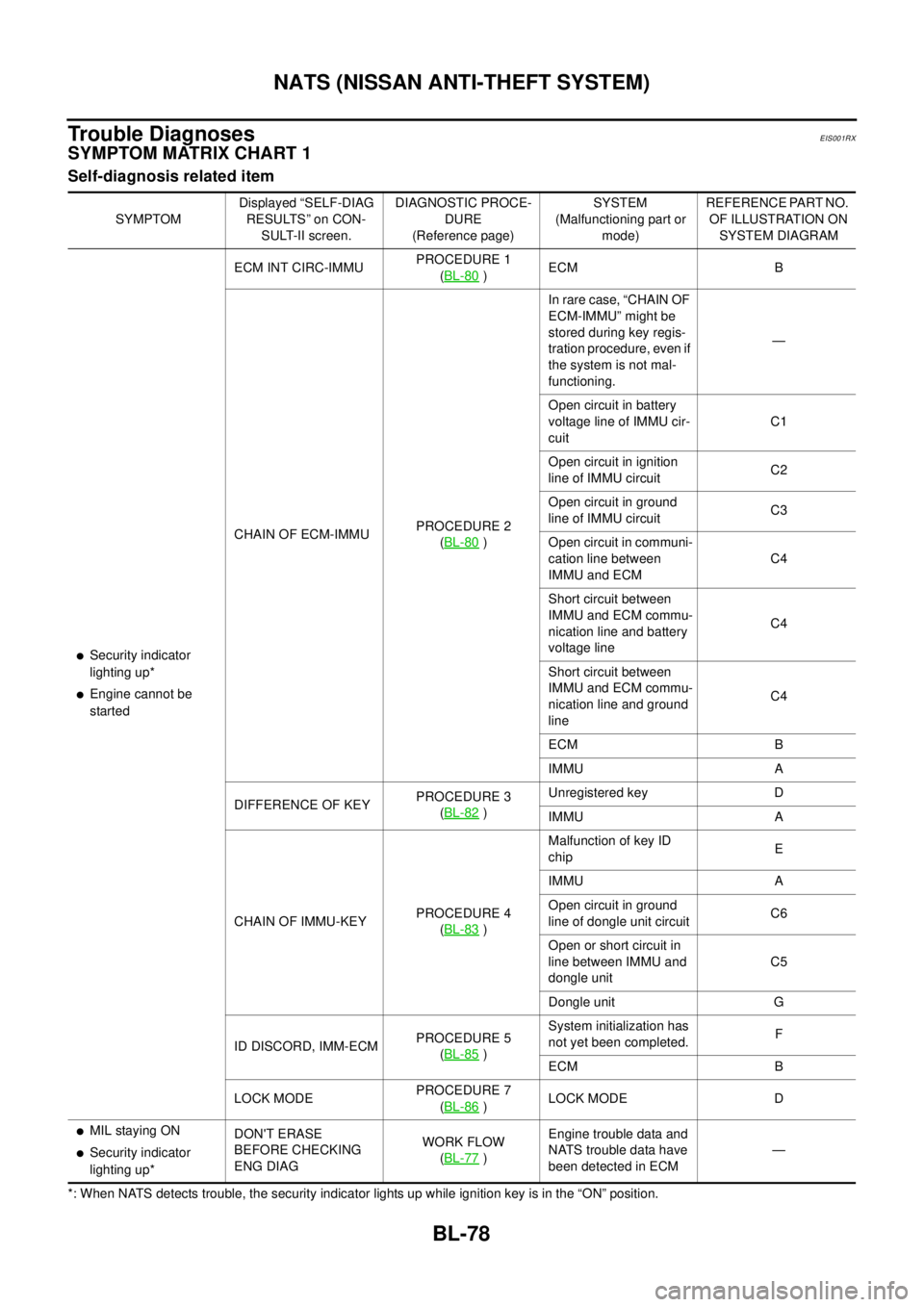
Trouble Diagnoses
EIS001RX
SYMPTOM MATRIX CHART 1
Self-diagnosis related item
*: When NATS detects trouble, the security indicator lights up while ignition key is in the “ON” position.SYMPTOMDisplayed “SELF-DIAG
RESULTS ” on CON-
SULT-II screen.DIAGNOSTIC PROCE-
DURE
(Reference page)SYSTEM
(Malfunctioning part or
mode)REFERENCE PART NO.
OF ILLUSTRATION ON
SYSTEM DIAGRAM
lSecurity indicator
lighting up*
lEngine cannot be
startedECM INT CIRC-IMMUPROCEDURE 1
(BL-80
)ECM B
CHAIN OF ECM-IMMUPROCEDURE 2
(BL-80
)In rare case, “CHAIN OF
ECM-IMMU” might be
stored during key regis-
tration procedure, even if
the system is not mal-
functioning.—
Open circuit in battery
voltage line of IMMU cir-
cuitC1
Open circuit in ignition
line of IMMU circuitC2
Open circuit in ground
line of IMMU circuitC3
Open circuit in communi-
cation line between
IMMU and ECMC4
Short circuit between
IMMU and ECM commu-
nication line and battery
voltage lineC4
Short circuit between
IMMU and ECM commu-
nication line and ground
lineC4
ECM B
IMMU A
DIFFERENCE OF KEYPROCEDURE 3
(BL-82
)Unregistered key D
IMMU A
CHAIN OF IMMU-KEYPROCEDURE 4
(BL-83
)Malfunction of key ID
chipE
IMMU A
Open circuit in ground
line of dongle unit circuitC6
Open or short circuit in
line between IMMU and
dongle unitC5
Dongle unit G
ID DISCORD, IMM-ECMPROCEDURE 5
(BL-85
)System initialization has
not yet been completed.F
ECM B
LOCK MODEPROCEDURE 7
(BL-86
)LOCK MODE D
lMIL staying ON
lSecurity indicator
lighting up*DON'T ERASE
BEFORE CHECKING
ENG DIAGWORK FLOW
(BL-77)Engine trouble data and
NATS trouble data have
been detected in ECM—
Page 824 of 3066
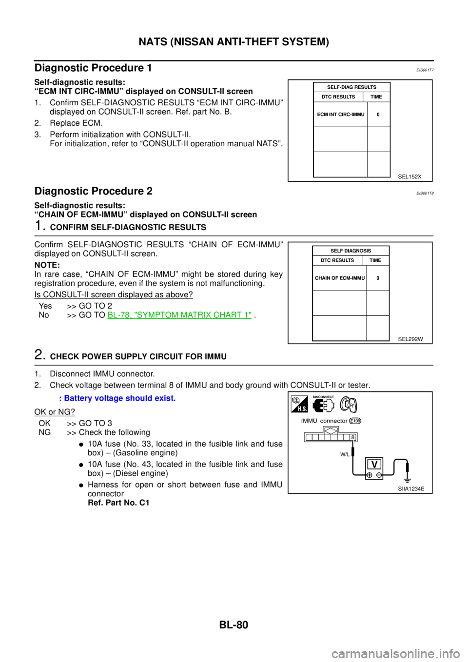
BL-80
NATS (NISSAN ANTI-THEFT SYSTEM)
Diagnostic Procedure 1
EIS001T7
Self-diagnostic results:
“ECM INT CIRC-IMMU” displayed on CONSULT-II screen
1. Confirm SELF-DIAGNOSTIC RESULTS “ECM INT CIRC-IMMU”
displayed on CONSULT-II screen. Ref. part No. B.
2. Replace ECM.
3. Perform initialization with CONSULT-II.
For initialization, refer to “CONSULT-II operation manual NATS”.
Diagnostic Procedure 2EIS001T8
Self-diagnostic results:
“CHAIN OF ECM-IMMU” displayed on CONSULT-II screen
1.CONFIRM SELF-DIAGNOSTIC RESULTS
Confirm SELF-DIAGNOSTIC RESULTS “CHAIN OF ECM-IMMU”
displayed on CONSULT-II screen.
NOTE:
In rare case, “CHAIN OF ECM-IMMU” might be stored during key
registration procedure, even if the system is not malfunctioning.
Is CONSULT-II screen displayed as above?
Yes >>GOTO2
No >> GO TOBL-78, "
SYMPTOM MATRIX CHART 1".
2.CHECK POWER SUPPLY CIRCUIT FOR IMMU
1. Disconnect IMMU connector.
2. Check voltage between terminal 8 of IMMU and body ground with CONSULT-II or tester.
OK or NG?
OK >> GO TO 3
NG >> Check the following
l10A fuse (No. 33, located in the fusible link and fuse
box) – (Gasoline engine)
l10A fuse (No. 43, located in the fusible link and fuse
box) – (Diesel engine)
lHarness for open or short between fuse and IMMU
connector
Ref. Part No. C1
SEL152X
SEL292W
: Battery voltage should exist.
SIIA1234E