NISSAN X-TRAIL 2003 Service Repair Manual
X-TRAIL 2003
NISSAN
NISSAN
https://www.carmanualsonline.info/img/5/57404/w960_57404-0.png
NISSAN X-TRAIL 2003 Service Repair Manual
Trending: warning lights, overheating, Dual fan circuit, spare wheel, immobilizer, height, bolt pattern
Page 3531 of 4179
AIR MIX DOOR MOTOR
ATC-135
C
D
E
F
G
H
I
K
L
MA
B
AT C
AIR MIX DOOR MOTOR PFP:27732
Removal and InstallationEJS004GK
REMOVAL
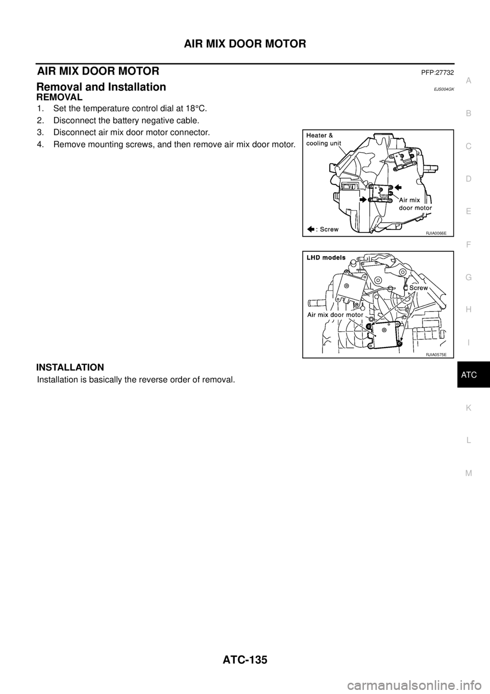
1. Set the temperature control dial at 18°C.
2. Disconnect the battery negative cable.
3. Disconnect air mix door motor connector.
4. Remove mounting screws, and then remove air mix door motor.
INSTALLATION
Installation is basically the reverse order of removal.
RJIA0066E
RJIA0575E
Page 3532 of 4179
ATC-136
HEATER CORE
HEATER COREPFP:27140
Removal and InstallationEJS004GJ
REMOVAL
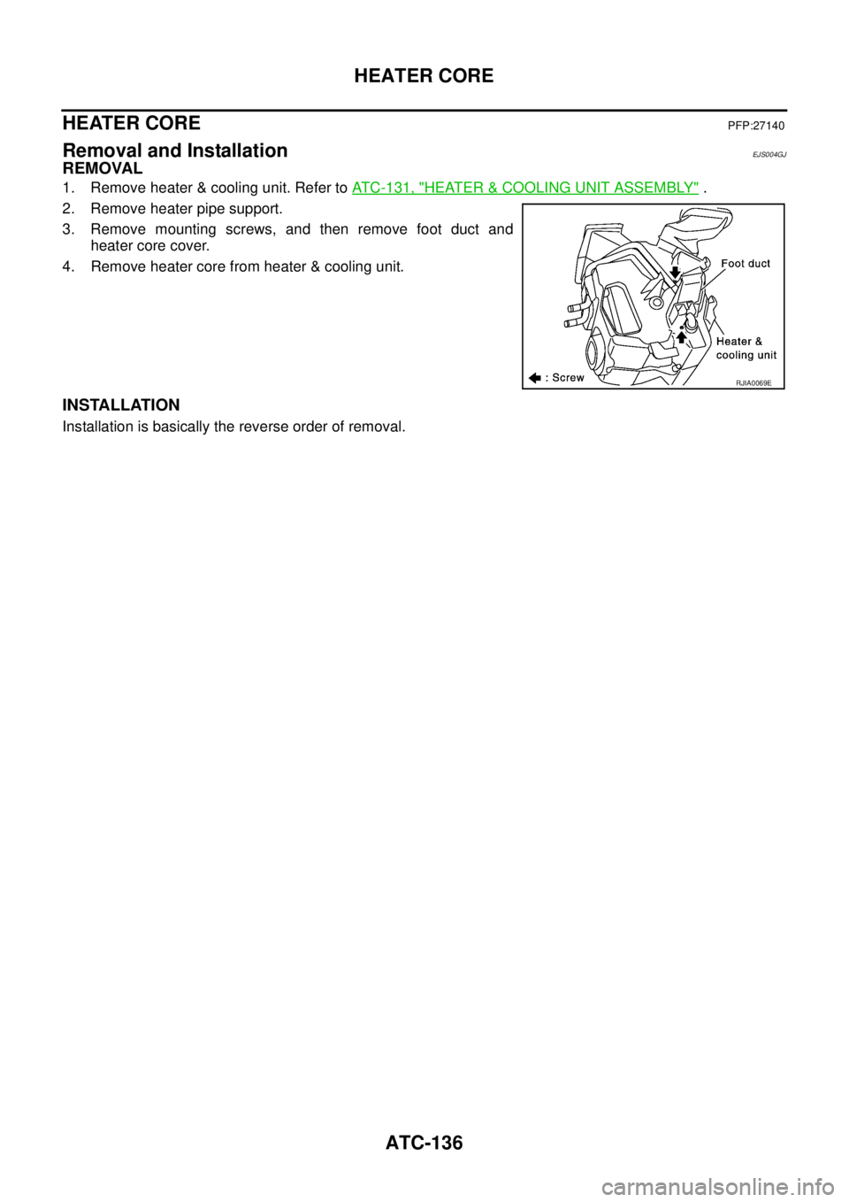
1. Remove heater & cooling unit. Refer to ATC-131, "HEATER & COOLING UNIT ASSEMBLY" .
2. Remove heater pipe support.
3. Remove mounting screws, and then remove foot duct and
heater core cover.
4. Remove heater core from heater & cooling unit.
INSTALLATION
Installation is basically the reverse order of removal.
RJIA0069E
Page 3533 of 4179
DUCTS AND GRILLES
ATC-137
C
D
E
F
G
H
I
K
L
MA
B
AT C
DUCTS AND GRILLESPFP:27860
Removal and InstallationEJS004GM
REMOVAL
NOTE:
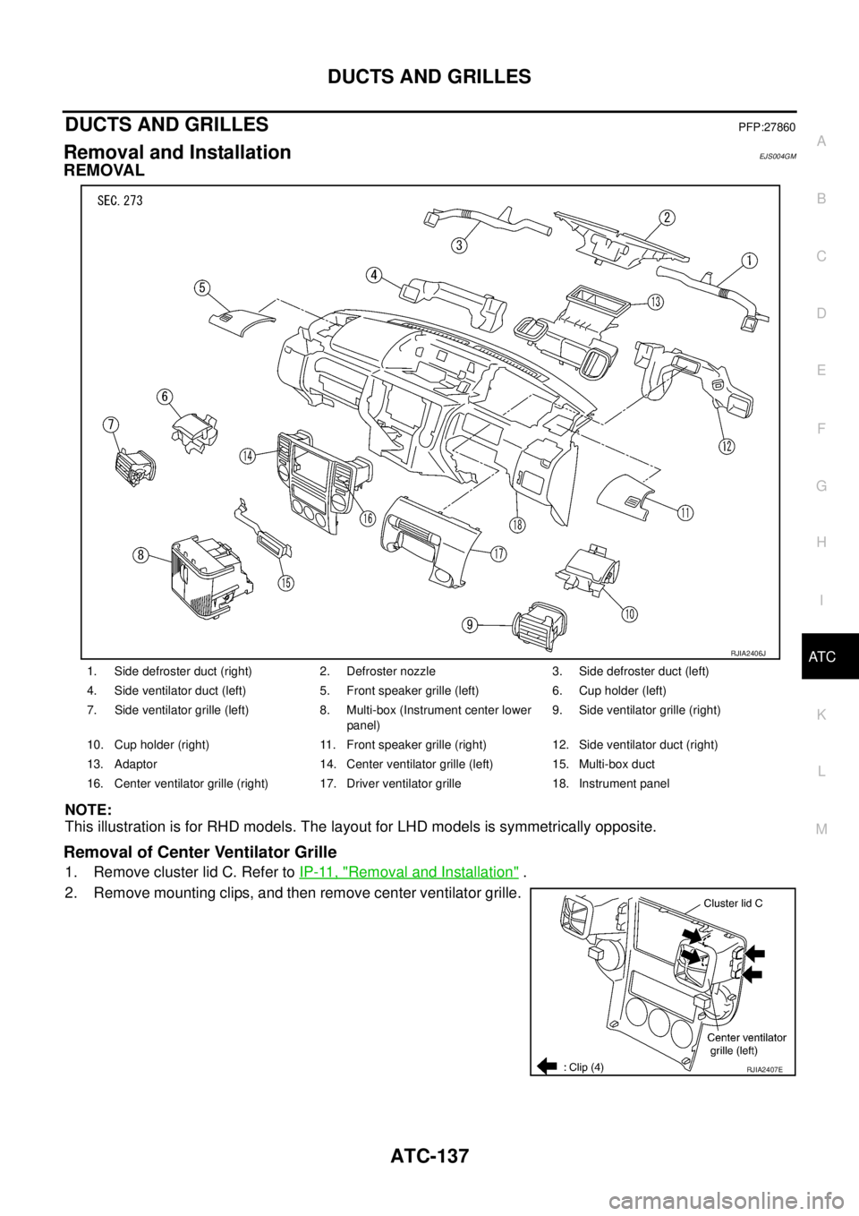
This illustration is for RHD models. The layout for LHD models is symmetrically opposite.
Removal of Center Ventilator Grille
1. Remove cluster lid C. Refer to IP-11, "Removal and Installation" .
2. Remove mounting clips, and then remove center ventilator grille.
1. Side defroster duct (right) 2. Defroster nozzle 3. Side defroster duct (left)
4. Side ventilator duct (left) 5. Front speaker grille (left) 6. Cup holder (left)
7. Side ventilator grille (left) 8. Multi-box (Instrument center lower
panel)9. Side ventilator grille (right)
10. Cup holder (right) 11. Front speaker grille (right) 12. Side ventilator duct (right)
13. Adaptor 14. Center ventilator grille (left) 15. Multi-box duct
16. Center ventilator grille (right) 17. Driver ventilator grille 18. Instrument panel
RJIA2406J
RJIA2407E
Page 3534 of 4179
ATC-138
DUCTS AND GRILLES
Removal of Side Ventilator Grille
1. Remove instrument panel. Refer to IP-11, "Removal and Installation" .
2. Remove side ventilator ducts. Refer to ATC-138, "
Removal of Defroster Nozzle, Duct and Side Ventilator
Duct" .
3. Remove mounting screws, and then side ventilator grille.
Removal of Driver Ventilator Grille
1. Remove instrument finisher. Refer to IP-11, "Removal and Installation" .
2. Remove mounting screws, and then remove driver ventilator
grille.
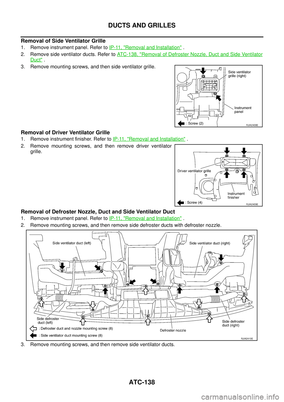
Removal of Defroster Nozzle, Duct and Side Ventilator Duct
1. Remove instrument panel. Refer to IP-11, "Removal and Installation" .
2. Remove mounting screws, and then remove side defroster ducts with defroster nozzle.
3. Remove mounting screws, and then remove side ventilator ducts.
RJIA2408E
RJIA2409E
RJIA2410E
Page 3535 of 4179
DUCTS AND GRILLES
ATC-139
C
D
E
F
G
H
I
K
L
MA
B
AT C
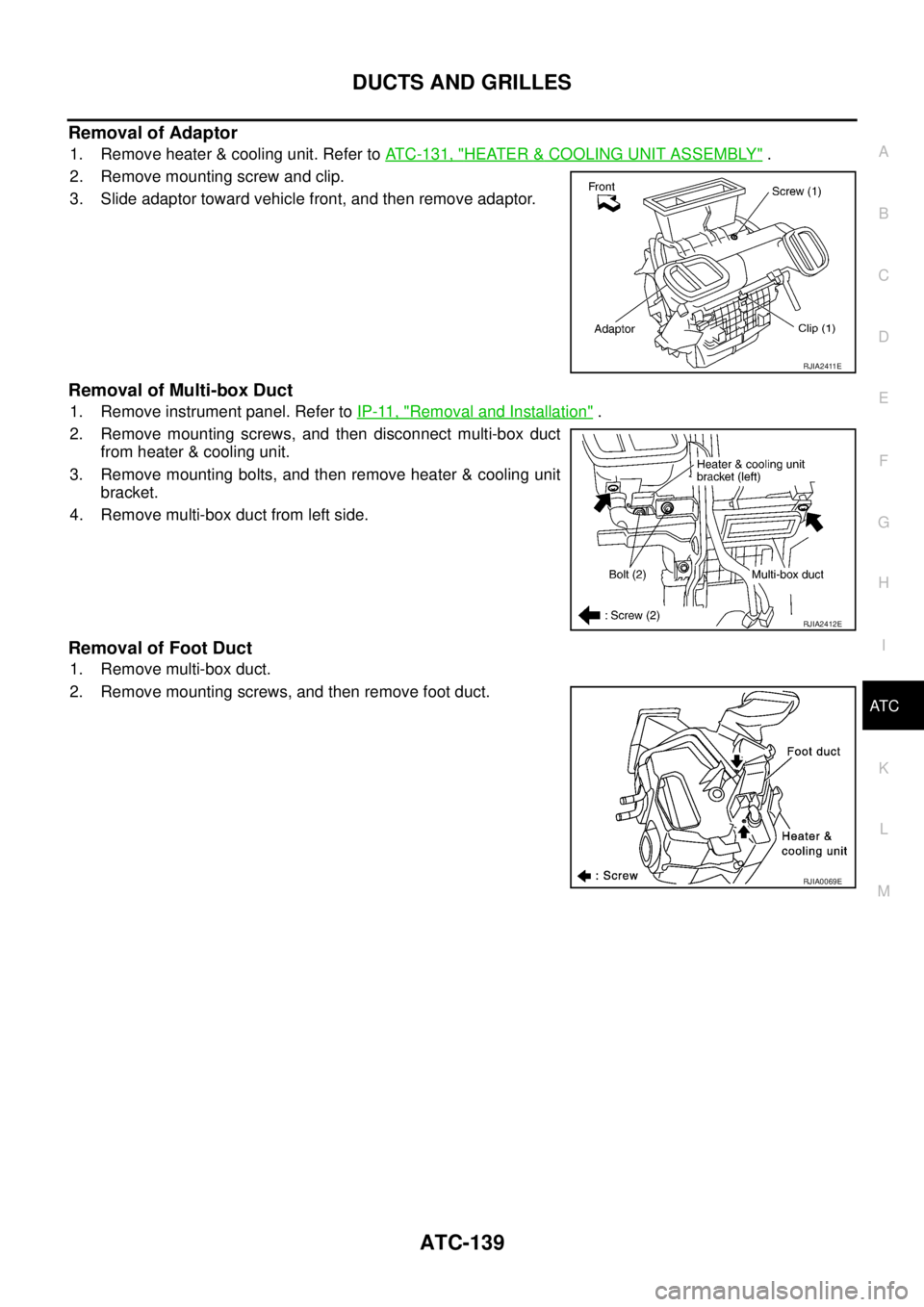
Removal of Adaptor
1. Remove heater & cooling unit. Refer to ATC-131, "HEATER & COOLING UNIT ASSEMBLY" .
2. Remove mounting screw and clip.
3. Slide adaptor toward vehicle front, and then remove adaptor.
Removal of Multi-box Duct
1. Remove instrument panel. Refer to IP-11, "Removal and Installation" .
2. Remove mounting screws, and then disconnect multi-box duct
from heater & cooling unit.
3. Remove mounting bolts, and then remove heater & cooling unit
bracket.
4. Remove multi-box duct from left side.
Removal of Foot Duct
1. Remove multi-box duct.
2. Remove mounting screws, and then remove foot duct.
RJIA2411E
RJIA2412E
RJIA0069E
Page 3536 of 4179
ATC-140
DUCTS AND GRILLES
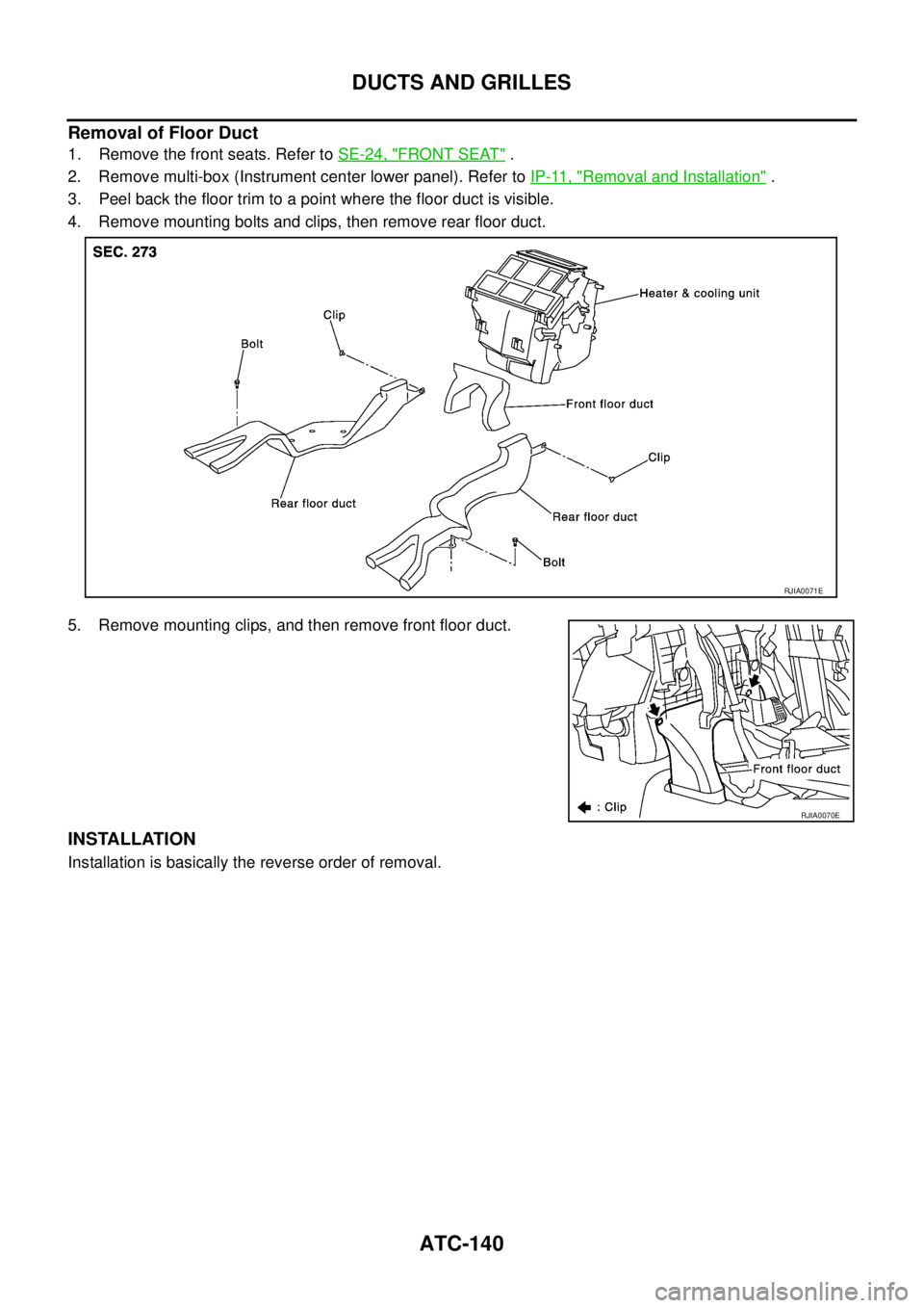
Removal of Floor Duct
1. Remove the front seats. Refer to SE-24, "FRONT SEAT" .
2. Remove multi-box (Instrument center lower panel). Refer to IP-11, "
Removal and Installation" .
3. Peel back the floor trim to a point where the floor duct is visible.
4. Remove mounting bolts and clips, then remove rear floor duct.
5. Remove mounting clips, and then remove front floor duct.
INSTALLATION
Installation is basically the reverse order of removal.
RJIA0071E
RJIA0070E
Page 3537 of 4179
REFRIGERANT LINES
ATC-141
C
D
E
F
G
H
I
K
L
MA
B
AT C
REFRIGERANT LINESPFP:92600
HFC-134a (R-134a) Service ProcedureEJS000V7
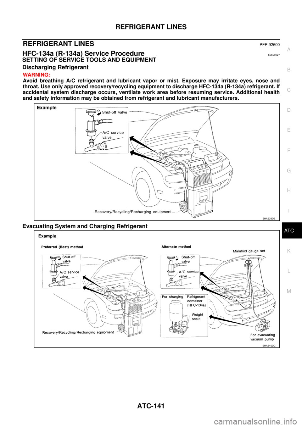
SETTING OF SERVICE TOOLS AND EQUIPMENT
Discharging Refrigerant
WARNING:
Avoid breathing A/C refrigerant and lubricant vapor or mist. Exposure may irritate eyes, nose and
throat. Use only approved recovery/recycling equipment to discharge HFC-134a (R-134a) refrigerant. If
accidental system discharge occurs, ventilate work area before resuming service. Additional health
and safety information may be obtained from refrigerant and lubricant manufacturers.
Evacuating System and Charging Refrigerant
SHA539DE
SHA540DC
Page 3538 of 4179
ATC-142
REFRIGERANT LINES
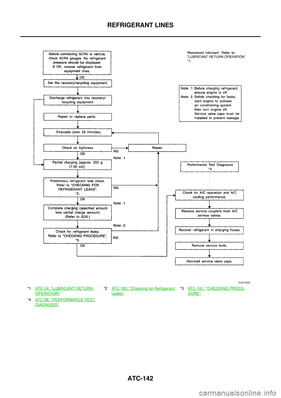
*1ATC-24, "LUBRICANT RETURN
OPERATION".*2ATC-160, "
Checking for Refrigerant
Leaks".*3ATC-161, "
CHECKING PROCE-
DURE".
*4ATC-98, "
PERFORMANCE TEST
DIAGNOSIS".
RJIA1940E
Page 3539 of 4179
REFRIGERANT LINES
ATC-143
C
D
E
F
G
H
I
K
L
MA
B
AT C
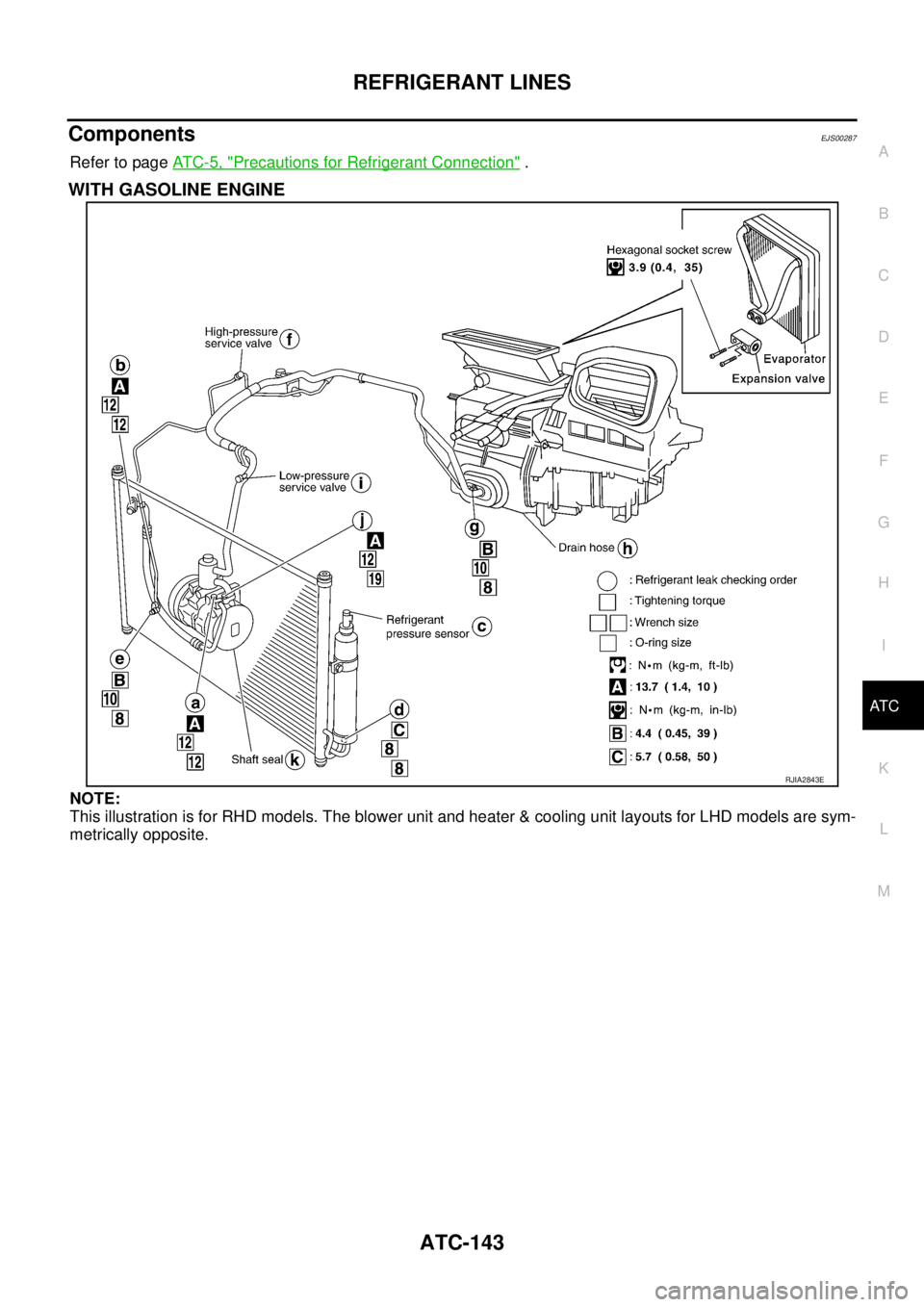
ComponentsEJS00287
Refer to page AT C - 5 , "Precautions for Refrigerant Connection" .
WITH GASOLINE ENGINE
NOTE:
This illustration is for RHD models. The blower unit and heater & cooling unit layouts for LHD models are sym-
metrically opposite.
RJIA2843E
Page 3540 of 4179
ATC-144
REFRIGERANT LINES
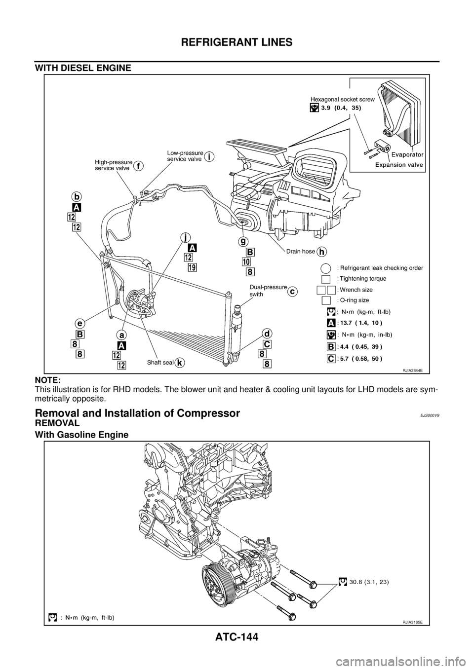
WITH DIESEL ENGINE
NOTE:
This illustration is for RHD models. The blower unit and heater & cooling unit layouts for LHD models are sym-
metrically opposite.
Removal and Installation of CompressorEJS000V9
REMOVAL
With Gasoline Engine
RJIA2844E
RJIA3185E
Trending: fuel consumption, alternator, fuse box location, change wheel, Oil cooler, air suspension, engine oil
