NISSAN X-TRAIL 2003 Service Repair Manual
X-TRAIL 2003
NISSAN
NISSAN
https://www.carmanualsonline.info/img/5/57404/w960_57404-0.png
NISSAN X-TRAIL 2003 Service Repair Manual
Trending: fuse box diagram, 4WD, gear, lock, ESP inoperative, fuel tank removal, ACCELERATOR PEDAL PEDAL POSITION SENSOR
Page 4161 of 4179
INTERIOR ROOM LAMP
LT-83
C
D
E
F
G
H
I
J
L
MA
B
LT
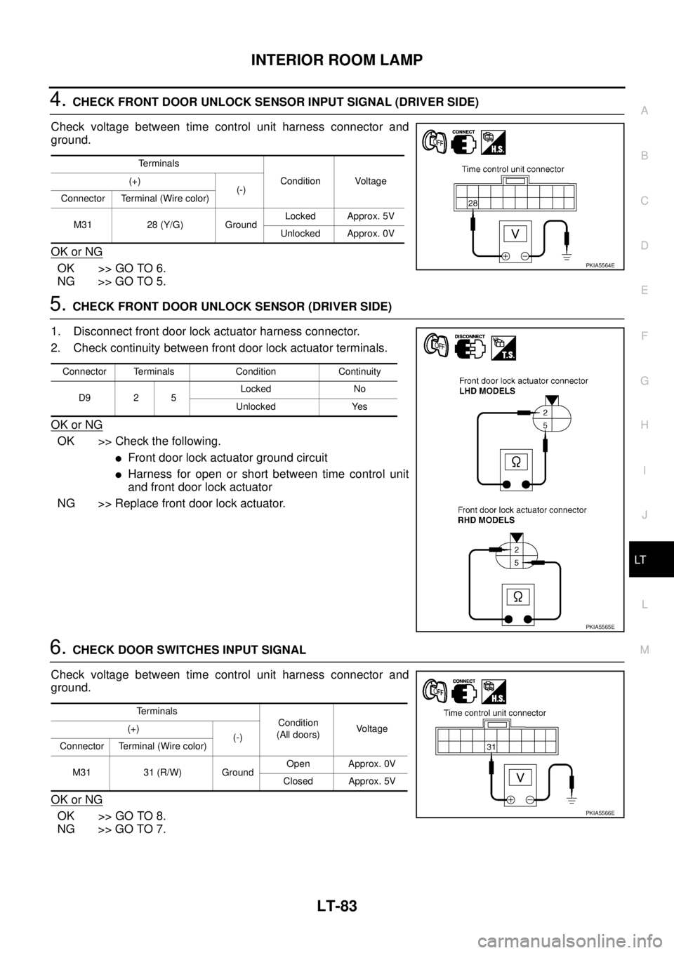
4. CHECK FRONT DOOR UNLOCK SENSOR INPUT SIGNAL (DRIVER SIDE)
Check voltage between time control unit harness connector and
ground.
OK or NG
OK >> GO TO 6.
NG >> GO TO 5.
5. CHECK FRONT DOOR UNLOCK SENSOR (DRIVER SIDE)
1. Disconnect front door lock actuator harness connector.
2. Check continuity between front door lock actuator terminals.
OK or NG
OK >> Check the following.
�Front door lock actuator ground circuit
�Harness for open or short between time control unit
and front door lock actuator
NG >> Replace front door lock actuator.
6. CHECK DOOR SWITCHES INPUT SIGNAL
Check voltage between time control unit harness connector and
ground.
OK or NG
OK >> GO TO 8.
NG >> GO TO 7.
Terminals
Condition Voltage (+)
(-)
Connector Terminal (Wire color)
M31 28 (Y/G) GroundLocked Approx. 5V
Unlocked Approx. 0V
PKIA5564E
Connector Terminals Condition Continuity
D9 2 5Locked No
Unlocked Yes
PKIA5565E
Te r m i n a l s
Condition
(All doors)Voltage (+)
(-)
Connector Terminal (Wire color)
M31 31 (R/W) GroundOpen Approx. 0V
Closed Approx. 5V
PKIA5566E
Page 4162 of 4179
LT-84
INTERIOR ROOM LAMP
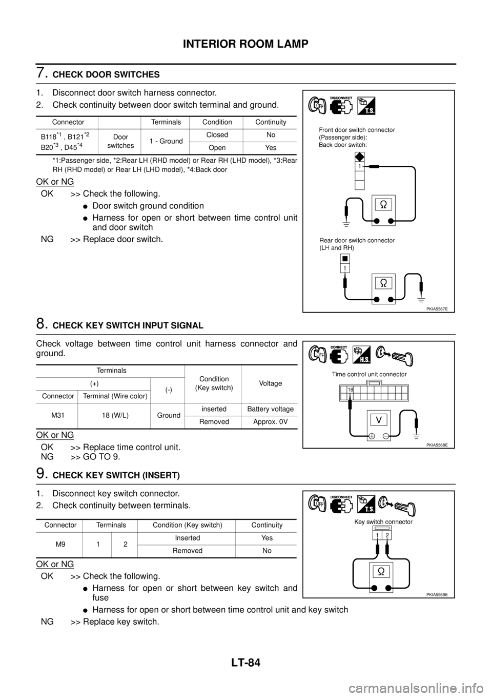
7. CHECK DOOR SWITCHES
1. Disconnect door switch harness connector.
2. Check continuity between door switch terminal and ground.
*1:Passenger side, *2:Rear LH (RHD model) or Rear RH (LHD model), *3:Rear
RH (RHD model) or Rear LH (LHD model), *4:Back door
OK or NG
OK >> Check the following.
�Door switch ground condition
�Harness for open or short between time control unit
and door switch
NG >> Replace door switch.
8. CHECK KEY SWITCH INPUT SIGNAL
Check voltage between time control unit harness connector and
ground.
OK or NG
OK >> Replace time control unit.
NG >> GO TO 9.
9. CHECK KEY SWITCH (INSERT)
1. Disconnect key switch connector.
2. Check continuity between terminals.
OK or NG
OK >> Check the following.
�Harness for open or short between key switch and
fuse
�Harness for open or short between time control unit and key switch
NG >> Replace key switch.
Connector Terminals Condition Continuity
B118
*1 , B121*2
B20*3 , D45*4Door
switches1 - GroundClosed No
Open Yes
PKIA5567E
Terminals
Condition
(Key switch)Voltage (+)
(-)
Connector Terminal (Wire color)
M31 18 (W/L) Groundinserted Battery voltage
Removed Approx. 0V
PKIA5568E
Connector Terminals Condition (Key switch) Continuity
M9 1 2Inserted Yes
Removed No
PKIA5569E
Page 4163 of 4179
INTERIOR ROOM LAMP
LT-85
C
D
E
F
G
H
I
J
L
MA
B
LT
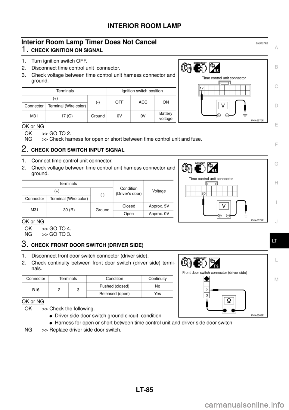
Interior Room Lamp Timer Does Not CancelEKS0079Q
1. CHECK IGNITION ON SIGNAL
1. Turn ignition switch OFF.
2. Disconnect time control unit connector.
3. Check voltage between time control unit harness connector and
ground.
OK or NG
OK >> GO TO 2.
NG >> Check harness for open or short between time control unit and fuse.
2. CHECK DOOR SWITCH INPUT SIGNAL
1. Connect time control unit connector.
2. Check voltage between time control unit harness connector and
ground.
OK or NG
OK >> GO TO 4.
NG >> GO TO 3.
3. CHECK FRONT DOOR SWITCH (DRIVER SIDE)
1. Disconnect front door switch connector (driver side).
2. Check continuity between front door switch (driver side) termi-
nals.
OK or NG
OK >> Check the following.
�Driver side door switch ground circuit condition
�Harness for open or short between time control unit and driver side door switch
NG >> Replace driver side door switch.
Terminals Ignition switch position
(+)
(-) OFF ACC ON
Connector Terminal (Wire color)
M31 17 (G) Ground 0V 0VBattery
voltage
PKIA5570E
Terminals
Condition
(Driver's door)Voltage (+)
(-)
Connector Terminal (Wire color)
M31 30 (R) GroundClosed Approx. 5V
Open Approx. 0V
PKIA5571E
Connector Terminals Condition Continuity
B16 2 3Pushed (closed) No
Released (open) Yes
PKIA5563E
Page 4164 of 4179
LT-86
INTERIOR ROOM LAMP
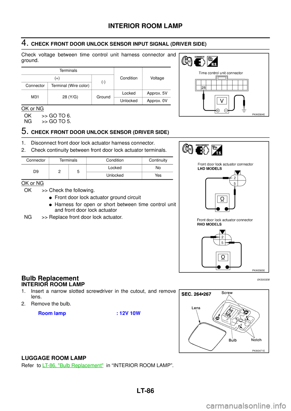
4. CHECK FRONT DOOR UNLOCK SENSOR INPUT SIGNAL (DRIVER SIDE)
Check voltage between time control unit harness connector and
ground.
OK or NG
OK >> GO TO 6.
NG >> GO TO 5.
5. CHECK FRONT DOOR UNLOCK SENSOR (DRIVER SIDE)
1. Disconnect front door lock actuator harness connector.
2. Check continuity between front door lock actuator terminals.
OK or NG
OK >> Check the following.
�Front door lock actuator ground circuit
�Harness for open or short between time control unit
and front door lock actuator
NG >> Replace front door lock actuator.
Bulb Replacement EKS003DB
INTERIOR ROOM LAMP
1. Insert a narrow slotted screwdriver in the cutout, and remove
lens.
2. Remove the bulb.
LUGGAGE ROOM LAMP
Refer to LT- 8 6 , "Bulb Replacement" in “INTERIOR ROOM LAMP”.
Terminals
Condition Voltage (+)
(-)
Connector Terminal (Wire color)
M31 28 (Y/G) GroundLocked Approx. 5V
Unlocked Approx. 0V
PKIA5564E
Connector Terminals Condition Continuity
D9 2 5Locked No
Unlocked Yes
PKIA5565E
Room lamp : 12V 10W
PKIA0471E
Page 4165 of 4179
INTERIOR ROOM LAMP
LT-87
C
D
E
F
G
H
I
J
L
MA
B
LT
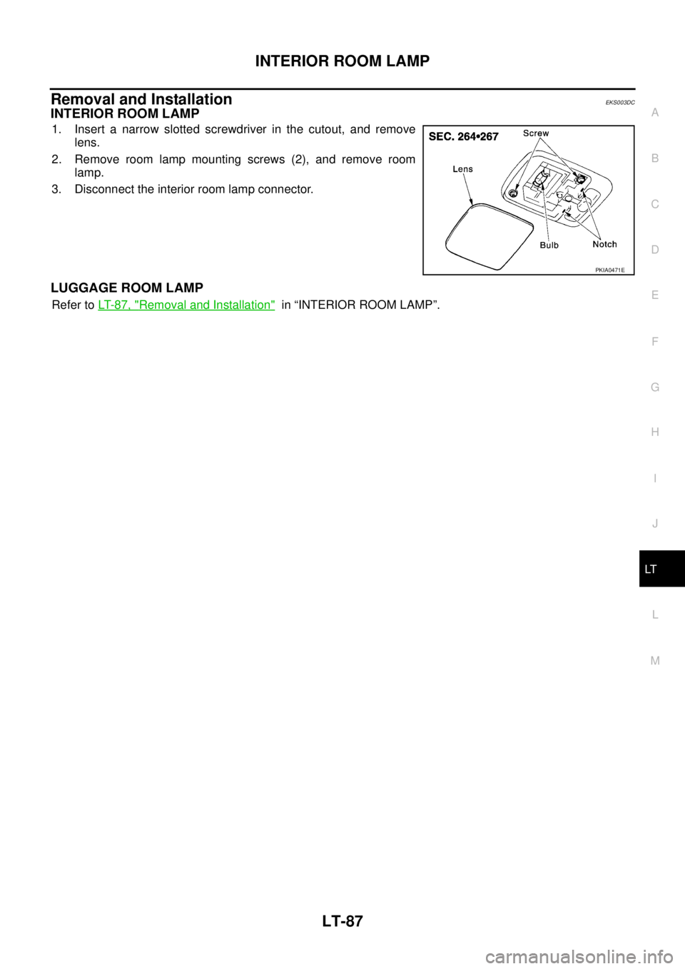
Removal and InstallationEKS003DC
INTERIOR ROOM LAMP
1. Insert a narrow slotted screwdriver in the cutout, and remove
lens.
2. Remove room lamp mounting screws (2), and remove room
lamp.
3. Disconnect the interior room lamp connector.
LUGGAGE ROOM LAMP
Refer to LT- 8 7 , "Removal and Installation" in “INTERIOR ROOM LAMP”.
PKIA0471E
Page 4166 of 4179
LT-88
STEP LAMP
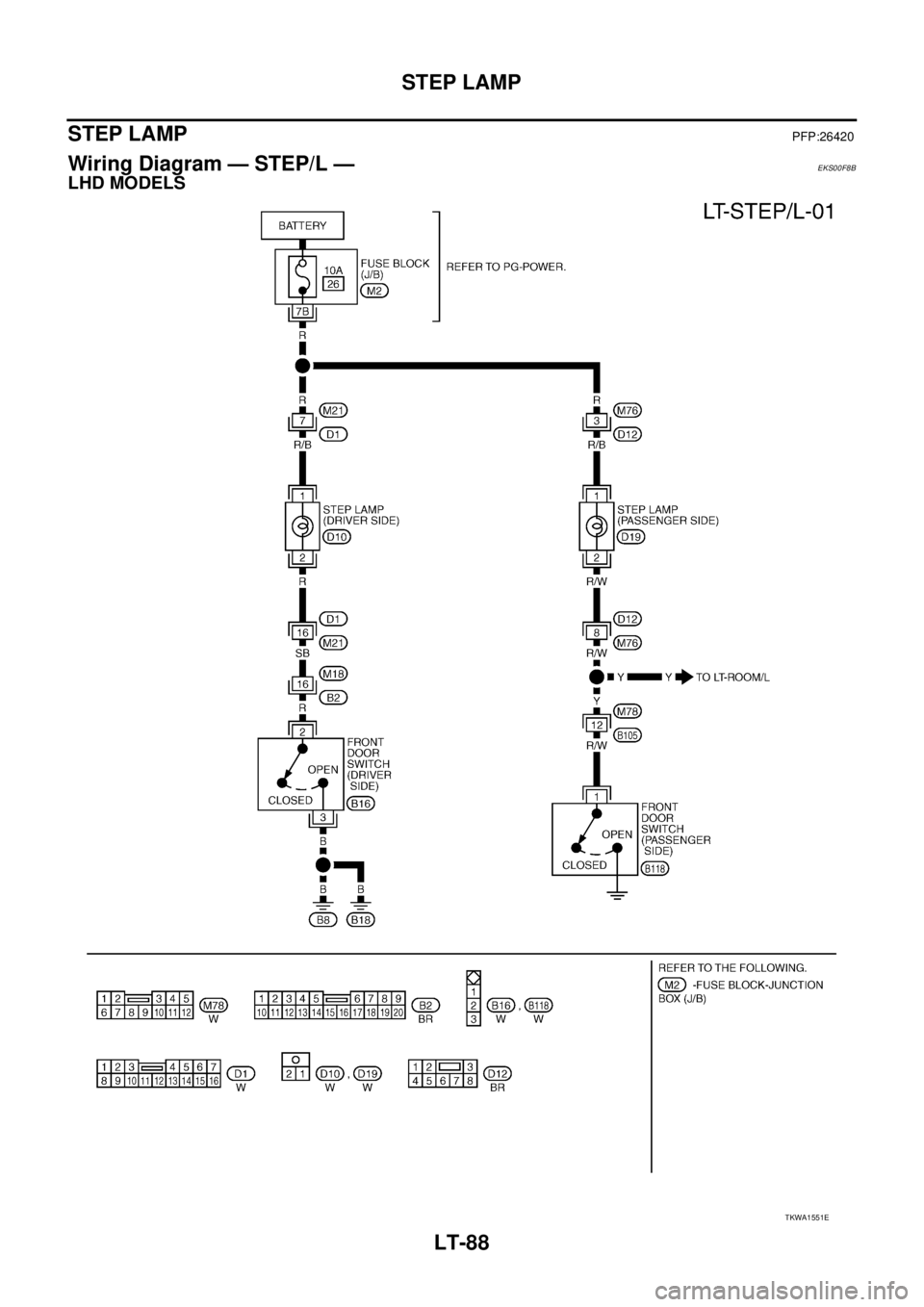
STEP LAMPPFP:26420
Wiring Diagram — STEP/L — EKS00F8B
LHD MODELS
TKWA1551E
Page 4167 of 4179
STEP LAMP
LT-89
C
D
E
F
G
H
I
J
L
MA
B
LT
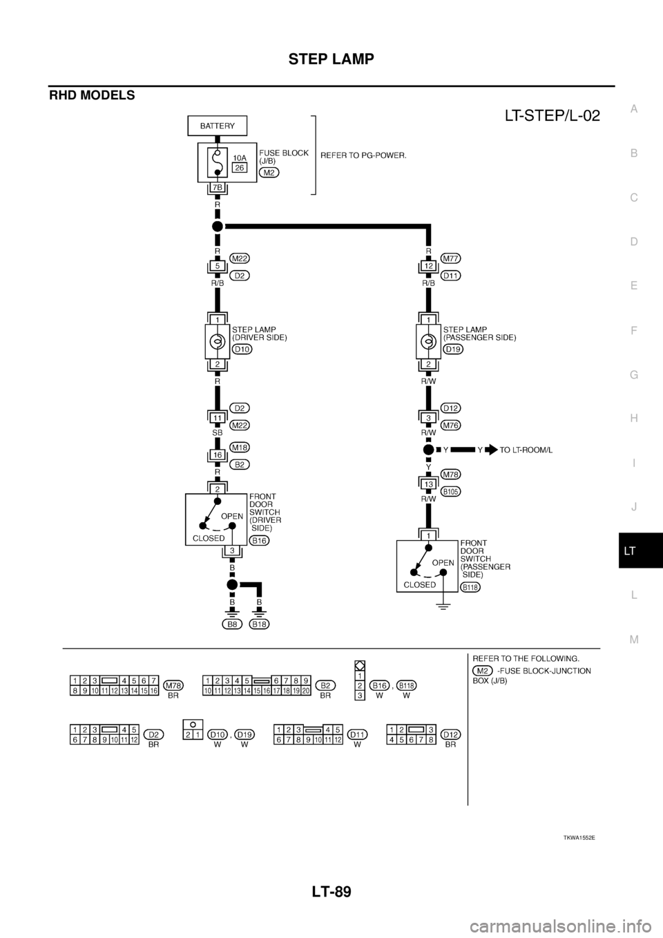
RHD MODELS
TKWA1552E
Page 4168 of 4179
LT-90
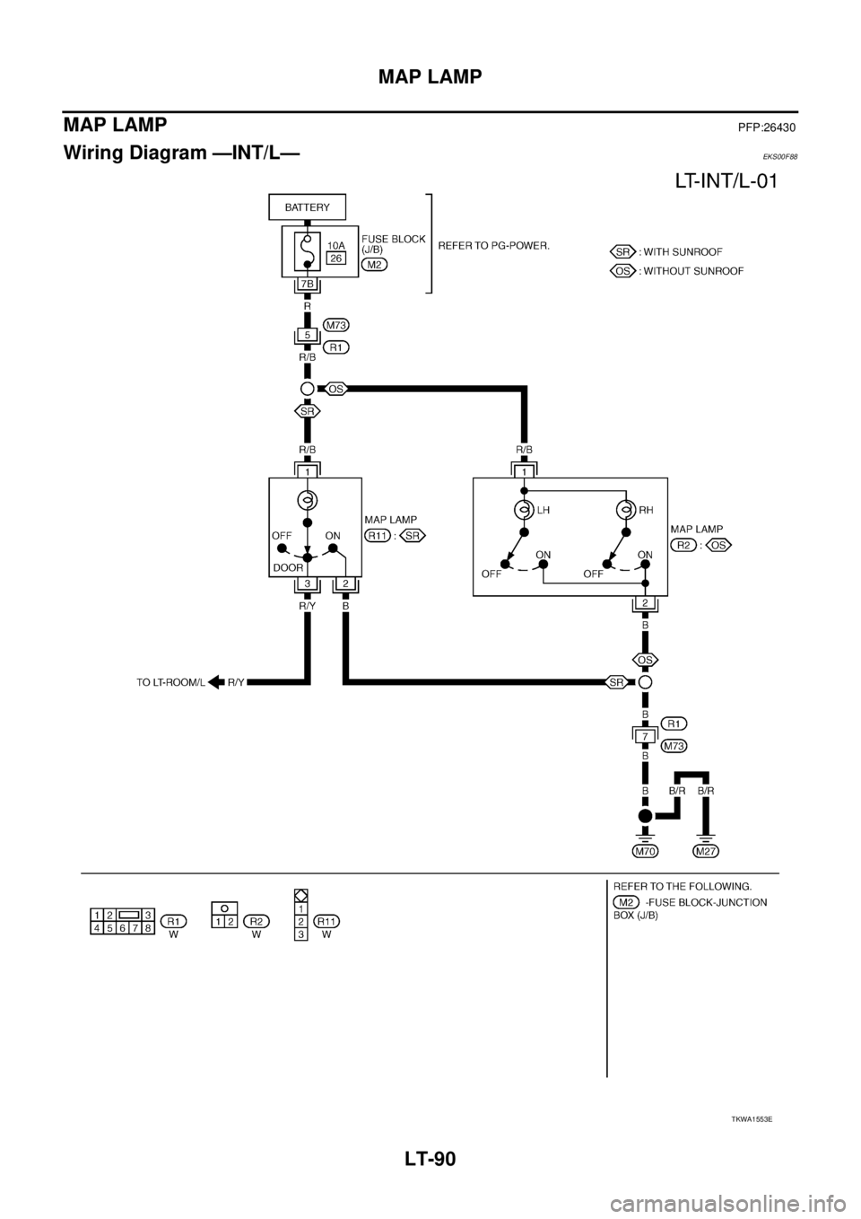
MAP LAMP
MAP LAMPPFP:26430
Wiring Diagram —INT/L—EKS00F88
TKWA1553E
Page 4169 of 4179
MAP LAMP
LT-91
C
D
E
F
G
H
I
J
L
MA
B
LT
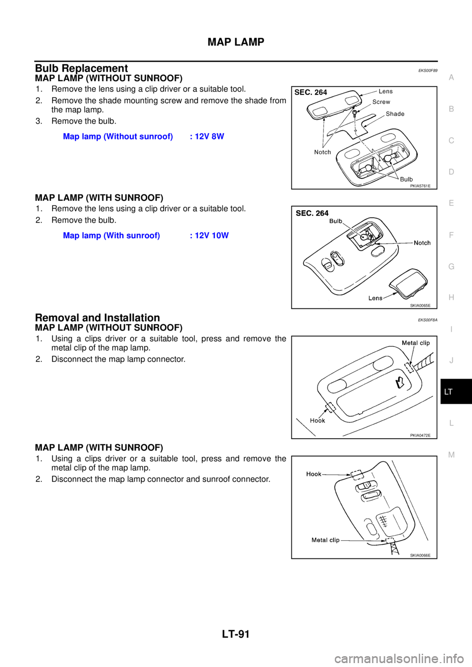
Bulb ReplacementEKS00F89
MAP LAMP (WITHOUT SUNROOF)
1. Remove the lens using a clip driver or a suitable tool.
2. Remove the shade mounting screw and remove the shade from
the map lamp.
3. Remove the bulb.
MAP LAMP (WITH SUNROOF)
1. Remove the lens using a clip driver or a suitable tool.
2. Remove the bulb.
Removal and InstallationEKS00F8A
MAP LAMP (WITHOUT SUNROOF)
1. Using a clips driver or a suitable tool, press and remove the
metal clip of the map lamp.
2. Disconnect the map lamp connector.
MAP LAMP (WITH SUNROOF)
1. Using a clips driver or a suitable tool, press and remove the
metal clip of the map lamp.
2. Disconnect the map lamp connector and sunroof connector.Map lamp (Without sunroof) : 12V 8W
PKIA5761E
Map lamp (With sunroof) : 12V 10W
SKIA0065E
PKIA0472E
SKIA0066E
Page 4170 of 4179
LT-92
BULB SPECIFICATIONS
BULB SPECIFICATIONSPFP:26297
HeadlampEKS003GS
Exterior LampEKS003GT
Interior Lamp/IlluminationEKS003GU
Item Wattage (W)
Low/High55 /60(H4)
Driving lamp65(H1R1)
Item Wattage (W)
Front combination lamp Clearance lamp 5
Front turn signal lamp21(amber)
Side turn signal lamp5
Fog lampFront fog lamp 55(H11)
Rear fog lamp 21
Rear combination lampStop/Tail lamp 21/5
Turn signal lamp 21
Back-up lamp 21
License plate lamp5
High-mounted stop lamp5
Item Wattage (W)
Ashtray illumination1.4
Interior room lamp10
Spot lampWithout sunroof 8
With sunroof 10
Luggage room lamp10
Trending: lumbar support, automatic transmission fluid, lights, dimensions, battery replacement, wheel bolt torque, PR-


