OLDSMOBILE SILHOUETTE 2003 Owners Manual
Manufacturer: OLDSMOBILE, Model Year: 2003, Model line: SILHOUETTE, Model: OLDSMOBILE SILHOUETTE 2003Pages: 466, PDF Size: 21.55 MB
Page 191 of 466
Rear Air Outlets
To increase airflow through the rear floor outlets, place
the left bucket seat in the second row in the forward
position. For more information, see “Seats” in the Index.
The outlet behind the left rear seat is the cold air
return outlet. Be sure to keep it free from obstructions.
Also, keep the area around the base of the center
instrument panel console, between and under the front
seats, free of objects that could also obstruct airflow
to the rear-seating area.
For more information on how to use the main climate
control system, see “Climate Controls” listed previously
in this section. For information on ventilation, see
“Outlet Adjustment” also listed previously in this section.
Rear Climate Control System
(With Entertainment System)
Your vehicle may have a rear climate-control system
that allows the driver to adjust the fan speed or a
rear-seat passenger to set a separate temperature
and adjust the fan speed, for the rear-seating area.
This system works with the main climate-control system
in your vehicle.
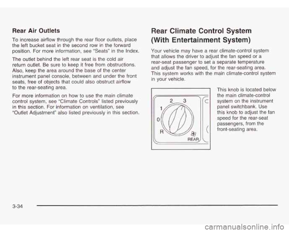
This knob is located below
the main climate-control system on the instrument
panel switchbank. Use
this knob to adjust the fan
speed for the rear-seat
passengers, from the
front-seating area.
3-34
Page 192 of 466
Directing the Airflow
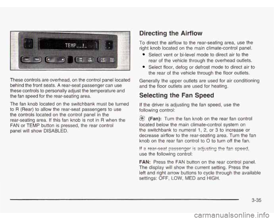
These controls are overhead, on the control panel located
behind the front seats.
A rear-seat passenger can use
these controls to personally adjust the temperature and
the fan speed for the rear-seating area.
The fan knob located on the switchbank must be turned
to
R (Rear) to allow the rear-seat passengers to use
the controls located on the control panel in the
rear-seating area.
If this fan knob is not in R when the
FAN or TEMP button is pressed, the rear control
panel will show
DISABLED.
To direct the airflow to the rear-seating area, use the
right knob located on the main climate-control panel.
Select vent or bi-level mode to direct air to the
rear of the vehicle through the overhead outlets.
Select floor, defog or defrost mode to direct air to
the rear of the vehicle through the floor outlets.
Generally the upper outlets are used for air conditioning
and the floor outlets are used for heating.
Selecting the Fan Speed
If the driver is adjusting the fan speed, use the
following control:
@ (Fan): Turn the fan knob on the rear fan control
located below the main climate-control system on
the switchbank to numeral
1, 2, or 3 to increase or
decrease airflow to the rear-seating area. Turn the fan
knob on the rear fan control to
0 to turn off the fan.
!? 9 rear-se2.t passenger IC 2dj!E?k?g the f2n speed,
use the following control:
FAN: Press the FAN button on the rear control panel.
The display will show the current setting. Press the
left and right arrow buttons to cycle through the available
settings:
OFF, LOW, MED and HIGH.
3-35
Page 193 of 466
Setting the Temperature
If the driver is adjusting the temperature, do the
following:
To increase or decrease the temperature for the entire
vehicle, use the temperature controls located on the
main climate-control panel.
If using the main climate-control panel, then the
air-conditioning system must be on to direct cooled air
to the rear of the vehicle.
If it is not on, then the
temperature in the rear of the vehicle will remain at
cabin temperature.
If a rear-seat passenger is adjusting the temperature,
do the following:
Press the TEMP button on the rear control panel.
Use the left arrow button to make the air cooler.
Use the right arrow button to make the air warmer.
Rear Air Outlets
To increase airflow through the rear floor outlets, place
the left bucket seat in the second row in the forward
position. For more information, see “Seats” in the Index.
The outlet behind the left rear seat is the cold air
return outlet. Be sure to keep it free from obstructions.
Also, keep the area around the base of the center
instrument panel console, between and under the front
seats, free of objects that could
also obstruct airflow
to the rear-seating area.
For more information on how to use the main climate
control system, see “Climate Controls” listed previously
in this section. For information on ventilation, see
“Outlet Adjustment” also listed previously in this section.
3-36
Page 194 of 466
Passenger Compartment Air Filter
Passenger compartment air, both outside and
recirculated air, is routed through a passenger
compartment filter. The filter removes certain
contaminants from the air, including pollen and dust
particles Reductions in airflow, which may occur more
quickly in dusty areas, indicate that the filter needs to be
replaced early. For how often to change the air filter, see
Part A: Scheduled Maintenance Services on page 6-4.
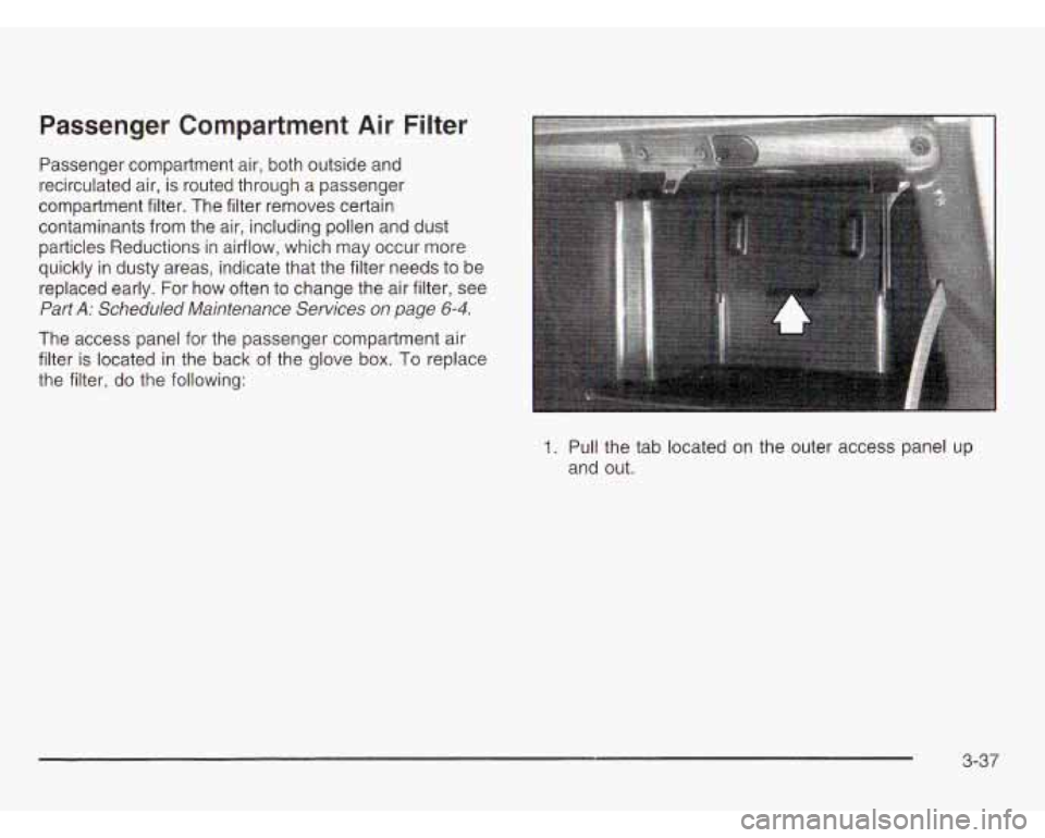
The access panel for the passenger compartment air
filter is located in the back of the glove box. To replace
the filter, do the following:
1. Pull the tab located on the outer access panel up
and out.
3-37
Page 195 of 466
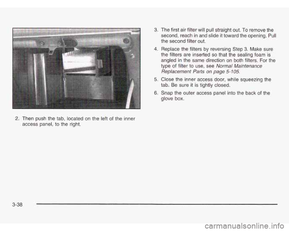
2. Then push the tab, located on the left of the inner
access panel, to the right.
3. The first air filter will pull straight out. To remove the
second, reach in and slide it toward the opening.
Pull
the second filter out.
4. Replace the filters by reversing Step 3. Make sure
the filters are inserted
so that the sealing foam is
angled in the same direction on both filters. For the
type of filter
to use, see Normal Maintenance
Replacement Parts on page
5- 105.
5. Close the inner access door, while squeezing the
6. Snap the outer access panel into the back of the
tab.
Be sure it is tightly closed.
glove box.
3-38
Page 196 of 466

Warning Lights, Gages and
Indicators
This part describes the warning lights and gages that
may be on your vehicle. The pictures will help you
locate them.
Warning lights and gages can signal that something is
wrong before
it becomes serious enough to cause
an expensive repair or replacement. Paying attention
to your warning lights and gages could also save you or
others from injury.
Warning lights come on when there may be or is a
problem with one of your vehicle’s functions.
As you
will see in the details on the next few pages, some
warning lights come on briefly when you start the engine
just to let you know they’re working.
If you are familiar
with this section, you should not be alarmed when
this happens. Gages
can indicate when there may be or is a problem
with one of your vehicle’s functions. Often gages
and warning lights work together to let you know when
there’s a problem with your vehicle.
When one of the warning lights comes on and stays
on
when you are driving, or when one of the gages shows
there may be a problem, check the section that tells you
what to do about it. Please follow this manual’s advice.
Waiting to do repairs can be costly
- and even
dangerous.
So please get to know your warning lights
and gages. They’re a big help.
Your vehicle also has a message center that works
along with the warning lights and gages. See
Message
Center on page
3-52.
3-39
Page 197 of 466
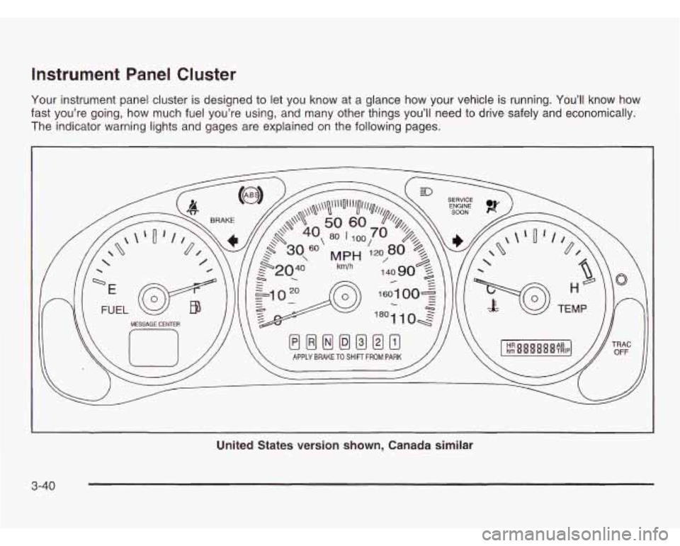
Instrument Panel Cluster
Your instrument panel cluster is designed to let you know at a glance how your vehicle is running. You’ll know how
fast you’re going, how much fuel you’re using, and many other things you’ll need
to drive safely and economically.
The indicator warning lights and gages are explained on the following pages.
United States version shown, Canada similar
3-40
Page 198 of 466
Speedometer and Odometer
Your speedometer lets you see your speed in both
miles per hour (mph) and kilometers per hour (km/h).
Your odometer shows how far your vehicle has
been driven, in either miles (used in the United States)
or kilometers (used in Canada).
Your vehicle has a tamper-resistant odometer.
You may wonder what happens
if your vehicle needs a
new odometer installed.
If the new one can be set to
the mileage total of the old odometer, then that will
be done.
If it can’t, then it’s set at zero and a label must
be put on the driver’s door to show the old mileage
reading when the new odometer was installed.
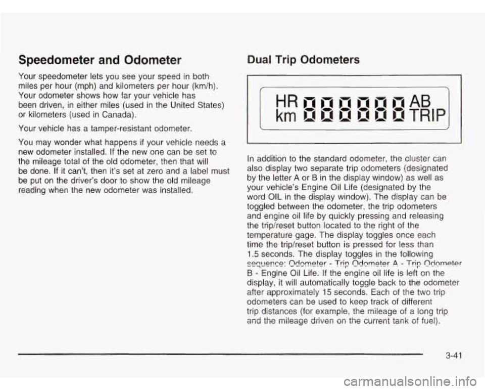
Dual Trip Odometers
In addition to the standard odometer, the cluster can
also display two separate trip odometers (designated
by the letter
A or B in the display window) as well as
your vehicle’s Engine Oil Life (designated by the
word
OIL in the display window). The display can be
toggled between the odometer, the trip odometers
and engine oil life by quickly pressing and releasing
the tripheset button located to the right of the
temperature gage. The display toggles once each
time the tripheset button is pressed for less than
1.5 seconds. The display toggles in the following
si?qwn~e: Q!km&r - Trip Qdnm~t~r .A. - Trip n&m@er
B - Engine Oil Life. If the engine oil life is left on the
display, it will automatically toggle back to the odometer
after approximately
15 seconds. Each of the two trip
odometers can be used to keep track of different
trip distances (for example, the mileage of
a long trip
and the mileage diiileii oi-i the cui-i-ei-it tank of fuel).
3-4 1
Page 199 of 466
The trip odometers will continue to keep track of
miles (kilometers) driven even
if they are not currently
displayed. To reset the odometer to zero
(0), press
and hold the tripheset button for at least
1.5 seconds,
but less than three seconds. Only the trip odometer that
is showing in the display will be reset.
Retro-Active Reset
Each of the two trip odometers has a feature callea
retro-active reset. This feature can be used to set
either (or both) trip odometer(s) to the number of miles
(kilometers) driven since the ignition was last turned
on. This can be used
if you forget to reset your
trip odometer at the beginning of a trip. To use the
retro-active reset feature, press and hold the tripheset
button for at least three seconds. The trip odometer
will then display the number of miles (kilometers) driven
since the ignition was last turned on and you began
driving. (If you use the retro-active reset feature
after you have started the vehicle, but before you begin
moving, the display will show the number of miles
(kilometers) you drove during the last ignition cycle.) Once you
begin driving, the trip odometer will
accumulate mileage. For example,
if you have driven
5.0 miles (8.0 km) since you started your vehicle,
and then activate the retro-active reset feature, the
display will show
5.0 miles (8.0 km). As you drive,
the display will then increase to
5.1 miles (8.2 km),
5.2 miles (8.4 km), etc. Only the trip odometer that is
displayed will be affected by the retro-active reset
so that both trip odometers can be used separately.
Safety Belt Reminder Light
When the key is turned to RUN or START, a chime will
come on for several seconds to remind people to
fasten their safety belts.
The safety belt light will also come on and stay
on for several seconds.
If the driver’s belt is
already buckled, neither
the chime nor the light
will come on.
3-42
Page 200 of 466
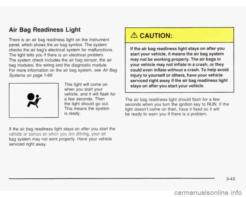
Air Bag Readiness Light
There is an air bag readiness light on the instrument
panel, which shows the air bag symbol. The system
checks the air bag’s electrical system for malfunctions.
The light tells you
if there is an electrical problem.
The system check includes the air bag sensor, the air
bag modules, the wiring and the diagnostic module.
For more information on the air bag system, see
Air Bag
Systems on page
1-69.
This light will come on
when you start your
vehicle, and it will flash for
a few seconds. Then
the light should go out.
This means the system
is ready.
If the air bag readiness light stays on after you start the
bag system may not work properly. Have your vehicle
serviced right away. .,nL;-lm nr n-mrrn nm ..rhn- ,,-ma qvn Av;~r;mrn \,A~*V qir VGIIIbIG VI bW111Ga VI1 YYIIGII YWU UI’V UiIViIIy’ YWUt UBI
If the air bag .eaG...ess light ,.ays on after y--
start your vehicle, it means the air bag system
may not be working properly. The air bags
in
your vehicle may not inflate in a crash, or they
could even inflate without a crash. To help avoid
injury to yourself or others, have your vehicle
serviced right away if the air bag readiness
light
stays on after you start your vehicle.
The air bag readiness light should flash for a few
seconds when you turn the ignition key to
RUN. If the
light doesn’t come on then, have it fixed
so it will
be ready to warn you
if there is a problem.
3-43