OPEL CORSA 2009 Owners Manual
CORSA 2009
OPEL
OPEL
https://www.carmanualsonline.info/img/37/58224/w960_58224-0.png
OPEL CORSA 2009 Owners Manual
Trending: instrument panel, sport mode, dashboard, technical data, timing belt, cooling, bonnet
Page 181 of 284
175
Driving and operation
Picture no: 18338s.tif
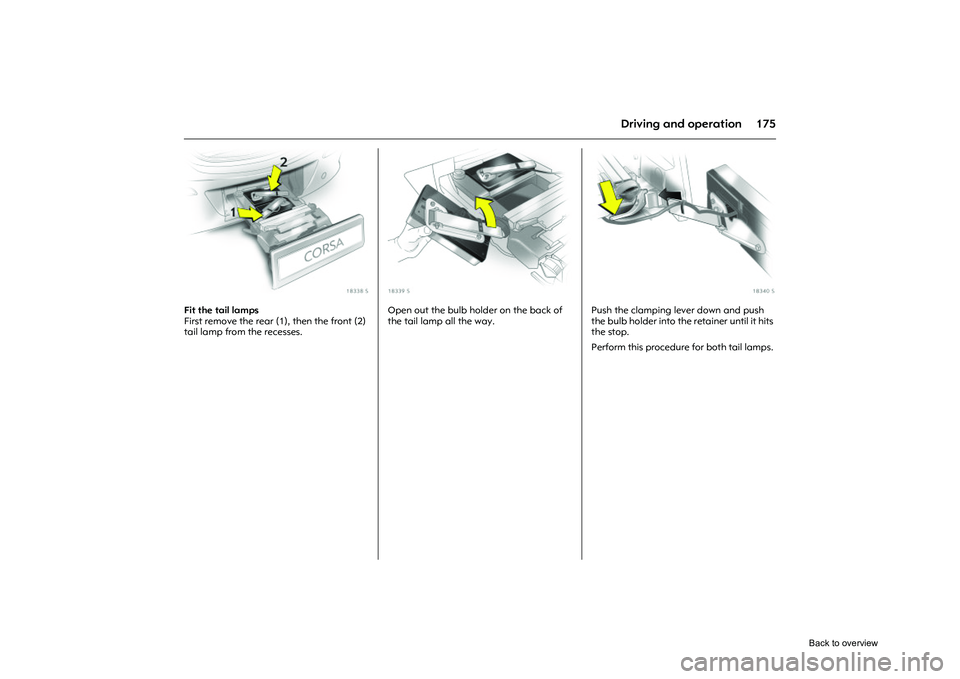
Fit the tail lamps
First remove the rear (1), then the front (2)
tail lamp from the recesses.
Picture no: 18339s.tif
Open out the bulb holder on the back of
the tail lamp all the way.
Picture no: 18340s.tif
Push the clamping lever down and push
the bulb holder into the retainer until it hits
the stop.
Perform this procedure for both tail lamps.
Back to overview
Page 182 of 284
176 Driving and operation
Picture no: 18341s.tif
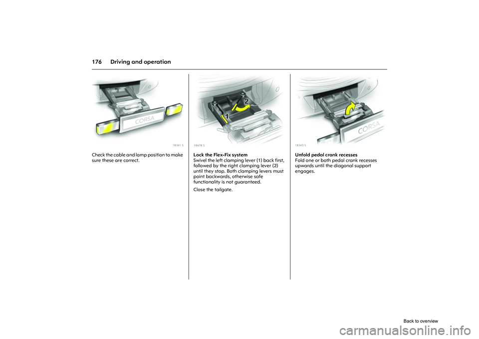
Check the cable and lamp position to make
sure these are correct.
Picture no: 18478s.tif
Lock the Flex-Fix system
Swivel the left clamping lever (1) back first,
followed by the right clamping lever (2)
until they stop. Both clamping levers must
point backwards, otherwise safe
functionality is not guaranteed.
Close the tailgate.
Picture no: 18343s.tif
Unfold pedal crank recesses
Fold one or both pedal crank recesses
upwards until the diagonal support
engages.
Back to overview
Page 183 of 284
177
Driving and operation
Picture no: 18344s.tif
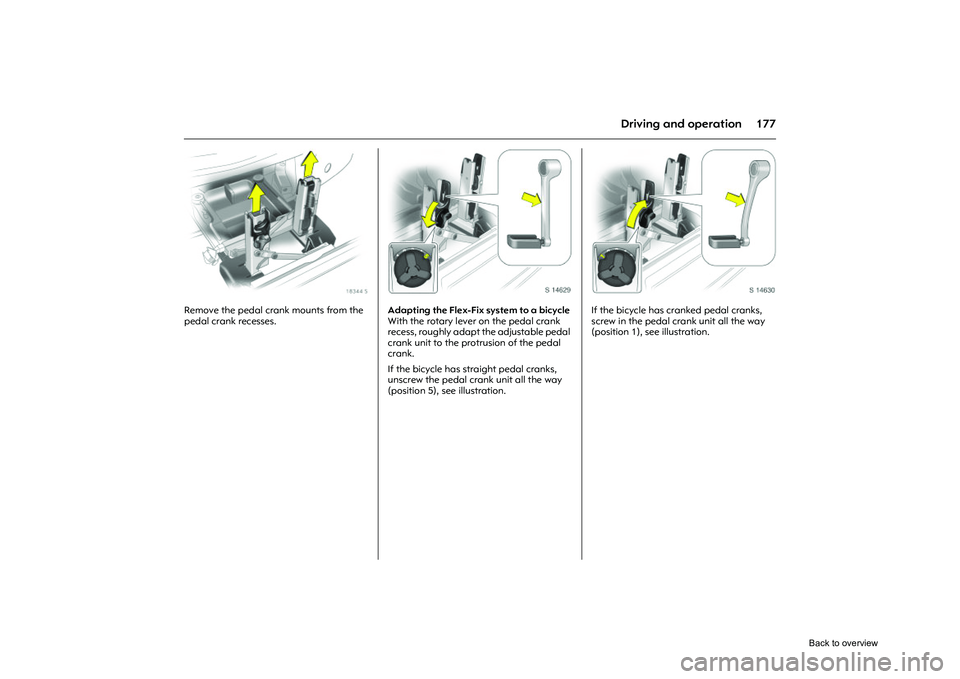
Remove the pedal crank mounts from the
pedal crank recesses.
Picture no: s0014629.tif
Adapting the Flex-Fix system to a bicycle
With the rotary lever on the pedal crank
recess, roughly adapt the adjustable pedal
crank unit to the protrusion of the pedal
crank.
If the bicycle has straight pedal cranks,
unscrew the pedal crank unit all the way
(position 5), see illustration.
Picture no: s0014630.tif
If the bicycle has cranked pedal cranks,
screw in the pedal crank unit all the way
(position 1), see illustration.
Back to overview
Page 184 of 284
178 Driving and operation
Picture no: 18347s.tif
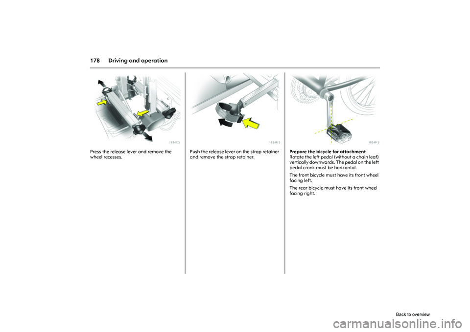
Press the release lever and remove the
wheel recesses.
Picture no: 18348s.tif
Push the release lever on the strap retainer
and remove the strap retainer.
Picture no: 18349s.tif
Prepare the bicycle for attachment
Rotate the left pedal (without a chain leaf)
vertically downwards. The pedal on the left
pedal crank must be horizontal.
The front bicycle must have its front wheel
facing left.
The rear bicycle must have its front wheel
facing right.
Back to overview
Page 185 of 284
179
Driving and operation
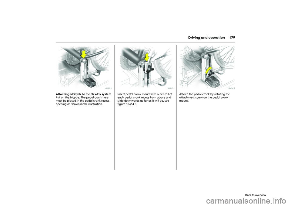
Picture no: 18350s.tif
Attaching a bicycle to the Flex-Fix system
Put on the bicycle. The pedal crank here
must be placed in the pedal crank recess
opening as shown in the illustration.
Picture no: 18351s.tif
Insert pedal crank mount into outer rail of
each pedal crank recess from above and
slide downwards as far as it will go, see
figure 18454 S.
Picture no: 18454s.tif
Attach the pedal crank by rotating the
attachment screw on the pedal crank
mount.
Back to overview
Page 186 of 284
180 Driving and operation
Picture no: 18353s.tif
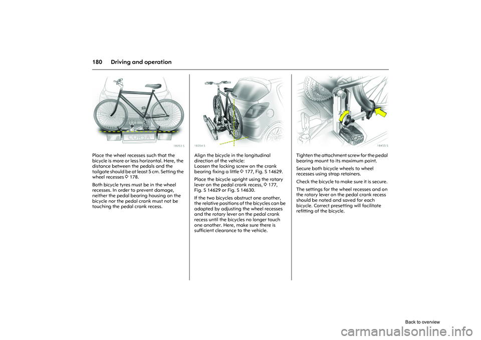
Place the wheel recesses such that the
bicycle is more or less horizontal. Here, the
distance between the pedals and the
tailgate should be at least 5 cm. Setting the
wheel recesses 3178.
Both bicycle tyres must be in the wheel
recesses. In order to prevent damage,
neither the pedal bearing housing on the
bicycle nor the pedal crank must not be
touching the pedal crank recess.
Picture no: 18354s.tif
Align the bicycle in the longitudinal
direction of the vehicle:
Loosen the locking screw on the crank
bearing fixing a little 3177, Fig. S 14629.
Place the bicycle upright using the rotary
lever on the pedal crank recess, 3177,
Fig. S 14629 or Fig. S 14630.
If the two bicycles obstruct one another,
the relative positions of the bicycles can be
adapted by adjusting the wheel recesses
and the rotary lever on the pedal crank
recess until the bicycles no longer touch
one another. Here, make sure there is
sufficient clearance to the vehicle.
Picture no: 18455s.tif
Tighten the attachment screw for the pedal
bearing mount to its maximum point.
Secure both bicycle wheels to wheel
recesses using strap retainers.
Check the bicycle to make sure it is secure.
The settings for the wheel recesses and on
the rotary lever on the pedal crank recess
should be noted and saved for each
bicycle. Correct presetting will facilitate
refitting of the bicycle.
Back to overview
Page 187 of 284
181
Driving and operation
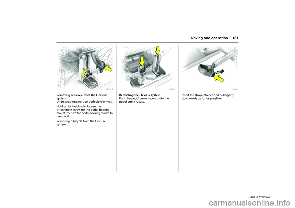
Picture no: 18456s.tif
Removing a bicycle from the Flex-Fix
system
Undo strap retainers on both bicycle tyres.
Hold on to the bicycle, loosen the
attachment screw for the pedal bearing
mount, then lift the pedal bearing mount to
remove it.
Removing a bicycle from the Flex-Fix
system.
Picture no: 18357s.tif
Retracting the Flex-Fix system
Push the pedal crank mounts into the
pedal crank recess.
Picture no: 18358s.tif
Insert the strap retainer and pull tightly
downwards as far as possible.
Back to overview
Page 188 of 284
182 Driving and operation
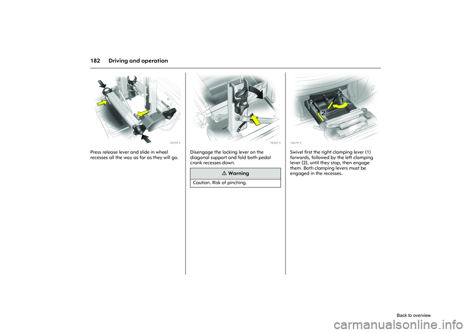
Picture no: 18359s.tif
Press release lever and slide in wheel
recesses all the way as far as they will go.
Picture no: 18360s.tif
Disengage the locking lever on the
diagonal support and fold both pedal
crank recesses down.
Picture no: 18479s.tif
Swivel first the right clamping lever (1)
forwards, followed by the left clamping
lever (2), until they stop, then engage
them. Both clamping levers must be
engaged in the recesses.
9
Warning
Caution. Risk of pinching.
Back to overview
Page 189 of 284
183
Driving and operation
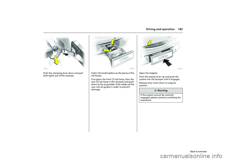
Picture no: 18362s.tif
Push the clamping lever down and pull
both lights out of the recesses.
Picture no: 18363s.tif
Fold in the bulb holders on the backs of the
tail lamps.
First place the front (1) tail lamp, then the
rear (2) tail lamp in the recesses and push
down as far as possible. Push cables all the
way into all guides in order to prevent
damage.
Picture no: 18364s.tif
Open the tailgate.
Push the release lever up and push the
system into the bumper until it engages.
Release lever must return to original
position.
9
Warning
If the system cannot be correctly
engaged, please contact a workshop for
assistance.
Back to overview
Page 190 of 284
184 Driving and operationTowing equipment
3
Only use towing equipment that has been
approved for your vehicle. Ask a workshop
to retrofit towing equipment. It may be
necessary to make changes that affect the
cooling system, heat shields or other
equipment.
Mounting dimensions of towing equipment
3269.
Stowage of coupling ball bar
The coupling ball bar is stowed in a bag in
the spare wheel well and secured to the
lashing eyes in the luggage compartment
3 187.
Picture no: 18389s.tif
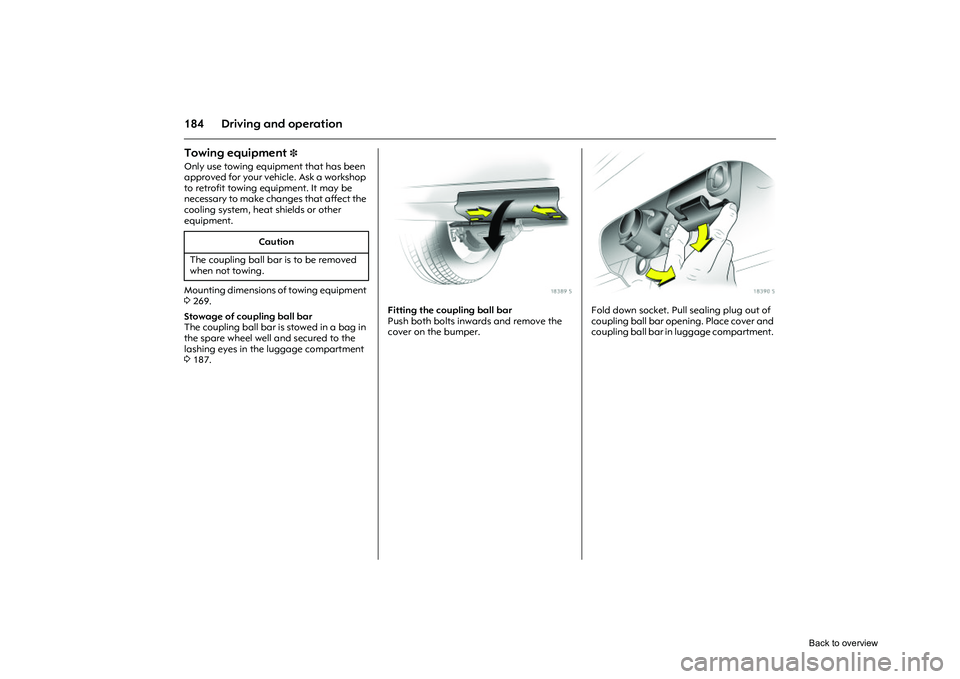
Fitting the coupling ball bar
Push both bolts inwards and remove the
cover on the bumper.
Picture no: 18390s.tif
Fold down socket. Pull sealing plug out of
coupling ball bar opening. Place cover and
coupling ball bar in luggage compartment.
Caution
The coupling ball bar is to be removed
when not towing.
Back to overview
Trending: maintenance reset, warning, change time, seat adjustment, tyre pressure, mirror, timing belt
