4WD OPEL FRONTERA 1998 Workshop Manual
[x] Cancel search | Manufacturer: OPEL, Model Year: 1998, Model line: FRONTERA, Model: OPEL FRONTERA 1998Pages: 6000, PDF Size: 97 MB
Page 4199 of 6000

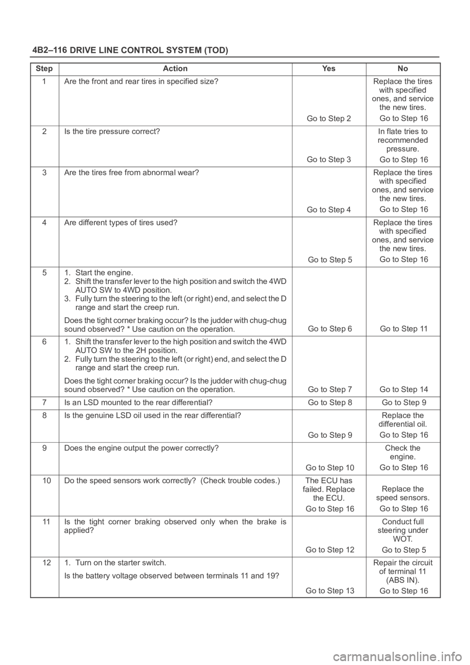
DRIVE LINE CONTROL SYSTEM (TOD) 4B2–116
StepActionYe sNo
1Are the front and rear tires in specified size?
Go to Step 2
Replace the tires
with specified
ones, and service
the new tires.
Go to Step 16
2Is the tire pressure correct?
Go to Step 3
In flate tries to
recommended
pressure.
Go to Step 16
3Are the tires free from abnormal wear?
Go to Step 4
Replace the tires
with specified
ones, and service
the new tires.
Go to Step 16
4Are different types of tires used?
Go to Step 5
Replace the tires
with specified
ones, and service
the new tires.
Go to Step 16
51. Start the engine.
2. Shift the transfer lever to the high position and switch the 4WD
AUTO SW to 4WD position.
3. Fully turn the steering to the left (or right) end, and select the D
range and start the creep run.
Does the tight corner braking occur? Is the judder with chug-chug
sound observed? * Use caution on the operation.
Go to Step 6 Go to Step 11
61. Shift the transfer lever to the high position and switch the 4WD
AUTO SW to the 2H position.
2. Fully turn the steering to the left (or right) end, and select the D
range and start the creep run.
Does the tight corner braking occur? Is the judder with chug-chug
sound observed? * Use caution on the operation.
Go to Step 7 Go to Step 14
7Is an LSD mounted to the rear differential? Go to Step 8 Go to Step 9
8Is the genuine LSD oil used in the rear differential?
Go to Step 9
Replace the
differential oil.
Go to Step 16
9Does the engine output the power correctly?
Go to Step 10
Check the
engine.
Go to Step 16
10Do the speed sensors work correctly? (Check trouble codes.)The ECU has
failed. Replace
the ECU.
Go to Step 16
Replace the
speed sensors.
Go to Step 16
11Is the tight corner braking observed only when the brake is
applied?
Go to Step 12
Conduct full
steering under
WOT.
Go to Step 5
121. Turn on the starter switch.
Is the battery voltage observed between terminals 11 and 19?
Go to Step 13
Repair the circuit
of terminal 11
(ABS IN).
Go to Step 16
Page 4200 of 6000

4B2–117 DRIVE LINE CONTROL SYSTEM (TOD)
StepNo Ye s Action
131. Apply the brake and fully turn the steering to the left (or right)
end, and start the creep run.
Does the voltage between terminals 4 and 20 range between 0.1
and 1.0V?Repair the
transfer
assembly.
Go to Step 16The ECU has
failed. Replace
the ECU.
Go to Step 16
141. Shift the transfer lever to the high position and switch the 4WD
AUTO SW to 4WD position.
2. Fully turn the steering to the left (or right) end, and select the D
range and start the creep run.
Does the voltage between terminals 4 and 20 range between 0.1
and 1.0V?
Go to Step 15 Go to Step 10
151. Select the 4WD AUTO SW to the 2WD position.
2. Jack up the right front wheel.
Does the front tire rotate smoothly?The phenomenon
is not
reproduced.
Refer to
“Troubles
intermittently
observed”.
Go to Step 16
Repair the
transfer
assembly.
Go to Step 16
16Check that all the parts are mounted.
Is this step complete?Repeat the
“Diagnosis Flow”.
Return to Step 16
*NOTE: Before checking this item, run the vehicle more
than 10 meters with the steering wheel in straight position
so that the 4L mechanical lock sleeve can be released
certainly.
Page 4201 of 6000

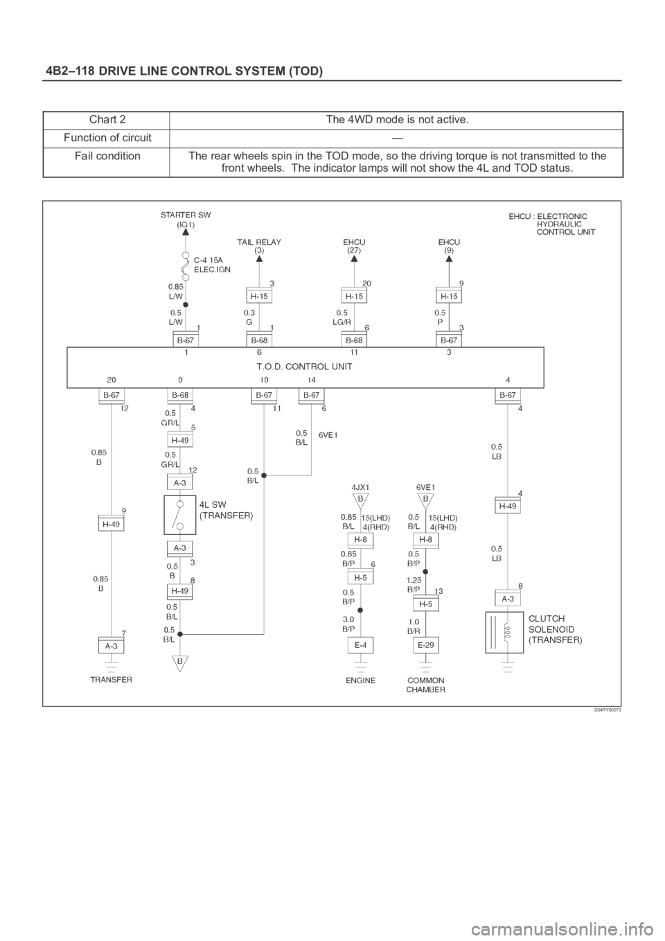
DRIVE LINE CONTROL SYSTEM (TOD) 4B2–118
Chart 2The 4WD mode is not active.
Function of circuit—
Fail conditionThe rear wheels spin in the TOD mode, so the driving torque is not transmitted to the
front wheels. The indicator lamps will not show the 4L and TOD status.
D04RY00073
Page 4206 of 6000

DRIVE LINE CONTROL SYSTEM (TOD) 4B2–123
Step Action Yes No
1 Are the brake and ABS systems healthy?
Go to Step 2Repair the
brake and ABS.
Refer to
section 5A.
2 Turn on the star ter switch.
Is the battery voltage observed between terminals 1 and 20?
Go to Step 3Repair the
battery system.
Go to Step 4
3 1. Select the 4WD AUTO SW to the 2WD position.
2. The voltage between terminals 3 and 19 range between 7.5
and 16V (0.12 seconds make a cycle)
Does the voltage within the range specified? Go to Step 4The ECU has
failed. Replace
the ECU.
Go to Step 4
4 Check that all the par ts are mounted.
Is this step complete?Repeat the
“Diagnosis Flow". Return to Step 4
Page 4262 of 6000

TRANSFER CASE (STANDARD TYPE)
4D1–1
DRIVELINE/AXLE
TRANSFER CASE (STANDARD TYPE)
CONTENTS
Service Precaution 4D1–1. . . . . . . . . . . . . . . . . . . . . .
General Description 4D1–2. . . . . . . . . . . . . . . . . . . . .
Transfer Rear Oil Seal 4D1–8. . . . . . . . . . . . . . . . . . .
Removal 4D1–8. . . . . . . . . . . . . . . . . . . . . . . . . . . . .
Installation 4D1–8. . . . . . . . . . . . . . . . . . . . . . . . . . . .
Transfer Case Assembly 4D1–9. . . . . . . . . . . . . . . . .
Removal 4D1–9. . . . . . . . . . . . . . . . . . . . . . . . . . . . .
Installation 4D1–10. . . . . . . . . . . . . . . . . . . . . . . . . . . .
Transfer Rear Cover Assembly
(4WD Switch Model) 4D1–11. . . . . . . . . . . . . . . . . . . .
Transfer Rear Cover Assembly and
Associated Parts 4D1–11. . . . . . . . . . . . . . . . . . . . . .
Removal 4D1–12. . . . . . . . . . . . . . . . . . . . . . . . . . . . .
Installation 4D1–13. . . . . . . . . . . . . . . . . . . . . . . . . . . .
Disassembly 4D1–16. . . . . . . . . . . . . . . . . . . . . . . . . .
Inspection and Repair 4D1–17. . . . . . . . . . . . . . . . . .
Reassembly 4D1–17. . . . . . . . . . . . . . . . . . . . . . . . . .
Transfer Rear Cover Assembly
(Except 4WD Switch Model) 4D1–19. . . . . . . . . . . . . . Transfer Rear Cover Assembly and
Associated Parts 4D1–19. . . . . . . . . . . . . . . . . . . . . .
Removal 4D1–20. . . . . . . . . . . . . . . . . . . . . . . . . . . . .
Installation 4D1–20. . . . . . . . . . . . . . . . . . . . . . . . . . . .
Disassembly 4D1–23. . . . . . . . . . . . . . . . . . . . . . . . . .
Inspection and Repair 4D1–24. . . . . . . . . . . . . . . . . .
Reassembly 4D1–24. . . . . . . . . . . . . . . . . . . . . . . . . .
Detent, Shift Arm, and Interlock Pin 4D1–26. . . . . . . .
Disassembled View 4D1–26. . . . . . . . . . . . . . . . . . . .
Disassembly 4D1–26. . . . . . . . . . . . . . . . . . . . . . . . . .
Inspection and Repair 4D1–28. . . . . . . . . . . . . . . . . .
Reassembly 4D1–28. . . . . . . . . . . . . . . . . . . . . . . . . .
Transfer Case Assembly 4D1–30. . . . . . . . . . . . . . . . .
Disassembled View 4D1–30. . . . . . . . . . . . . . . . . . . .
Disassembly 4D1–31. . . . . . . . . . . . . . . . . . . . . . . . . .
Inspection and Repair 4D1–33. . . . . . . . . . . . . . . . . .
Reassembly 4D1–37. . . . . . . . . . . . . . . . . . . . . . . . . .
Main Data and Specifications 4D1–43. . . . . . . . . . . . .
Special Tools 4D1–46. . . . . . . . . . . . . . . . . . . . . . . . . . .
Service Precaution
WARNING: THIS VEHICLE HAS A SUPPLEMENTAL
RESTRAINT SYSTEM (SRS). REFER TO THE SRS
COMPONENT AND WIRING LOCATION VIEW IN
ORDER TO DETERMINE WHETHER YOU ARE
PERFORMING SERVICE ON OR NEAR THE SRS
COMPONENTS OR THE SRS WIRING. WHEN YOU
ARE PERFORMING SERVICE ON OR NEAR THE SRS
COMPONENTS OR THE SRS WIRING, REFER TO
THE SRS SERVICE INFORMATION. FAILURE TO
FOLLOW WARNINGS COULD RESULT IN POSSIBLE
AIR BAG DEPLOYMENT, PERSONAL INJURY, OR
OTHERWISE UNNEEDED SRS SYSTEM REPAIRS.
CAUTION: Always use the correct fastener in the
proper location. When you replace a fastener, use
ONLY the exact part number for that application.
ISUZU will call out those fasteners that require a
replacement after removal. ISUZU will also call out
the fasteners that require thread lockers or thread
sealant. UNLESS OTHERWISE SPECIFIED, do not
use supplemental coatings (Paints, greases, or other
corrosion inhibitors) on threaded fasteners or
fastener joint interfaces. Generally, such coatings
adversely affect the fastener torque and the joint
clamping force, and may damage the fastener. When
you install fasteners, use the correct tightening
sequence and specifications. Following these
instructions can help you avoid damage to parts and
systems.
Page 4263 of 6000

4D1–2
TRANSFER CASE (STANDARD TYPE)
General Description
M/T, W/Shift On The Fly, W/4WD Switch, model
A07RW019
Page 4264 of 6000

TRANSFER CASE (STANDARD TYPE)
4D1–3
M/T, W/Shift On The Fly, WO/4WD Switch, model
A07RW054
Page 4265 of 6000

4D1–4
TRANSFER CASE (STANDARD TYPE)
M/T, WO/Shift On The Fly, WO/4WD Switch, model
A07RW053
Page 4266 of 6000

TRANSFER CASE (STANDARD TYPE)
4D1–5
A/T, W/Shift On The Fly, W/4WD Switch, model
A07RW001
Page 4267 of 6000

4D1–6
TRANSFER CASE (STANDARD TYPE)
A/T, W/Shift On The Fly, WO/4WD Switch, model
A07RW056