4WD OPEL FRONTERA 1998 Workshop Manual
[x] Cancel search | Manufacturer: OPEL, Model Year: 1998, Model line: FRONTERA, Model: OPEL FRONTERA 1998Pages: 6000, PDF Size: 97 MB
Page 4289 of 6000
4D1–28
TRANSFER CASE (STANDARD TYPE)
Inspection and Repair
Refer to “TRANSFER CASE ASSEMBLY” in this section
for inspection and repair.
Reassembly
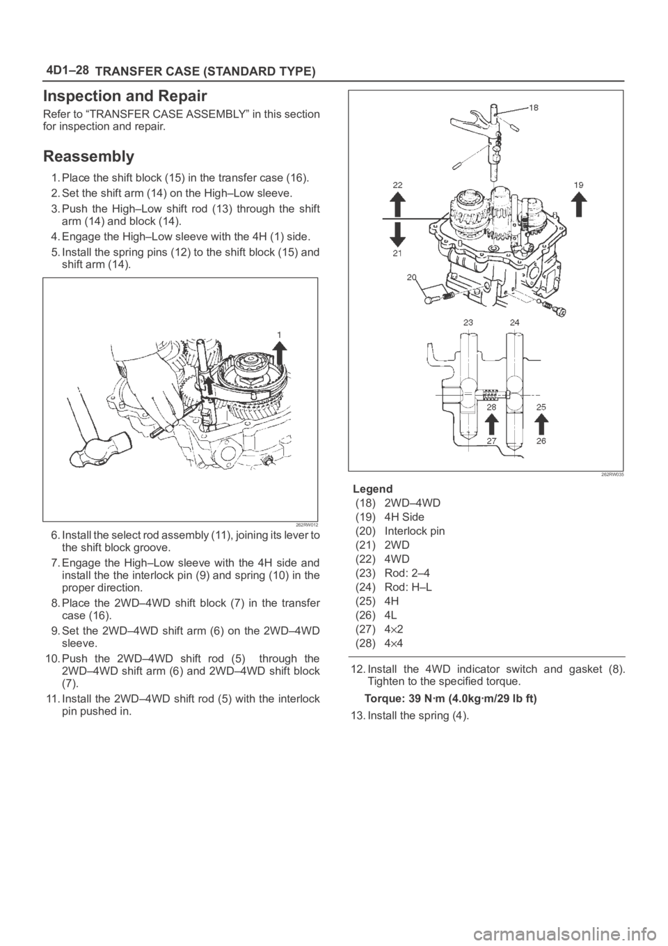
1. Place the shift block (15) in the transfer case (16).
2. Set the shift arm (14) on the High–Low sleeve.
3. Push the High–Low shift rod (13) through the shift
arm (14) and block (14).
4. Engage the High–Low sleeve with the 4H (1) side.
5. Install the spring pins (12) to the shift block (15) and
shift arm (14).
262RW012
6 . I n s t a l l t h e s e l e c t r o d a s s e m b l y ( 11 ) , j o i n i n g i t s l e v e r t o
the shift block groove.
7. Engage the High–Low sleeve with the 4H side and
install the the interlock pin (9) and spring (10) in the
proper direction.
8. Place the 2WD–4WD shift block (7) in the transfer
case (16).
9. Set the 2WD–4WD shift arm (6) on the 2WD–4WD
sleeve.
10. Push the 2WD–4WD shift rod (5) through the
2WD–4WD shift arm (6) and 2WD–4WD shift block
(7).
11. Install the 2WD–4WD shift rod (5) with the interlock
pin pushed in.
262RW035
Legend
(18) 2WD–4WD
(19) 4H Side
(20) Interlock pin
(21) 2WD
(22) 4WD
(23) Rod: 2–4
(24) Rod: H–L
(25) 4H
(26) 4L
(27) 4
2
(28) 4
4
12. Install the 4WD indicator switch and gasket (8).
Tighten to the specified torque.
Torque: 39 Nꞏm (4.0kgꞏm/29 lb ft)
13. Install the spring (4).
Page 4290 of 6000
TRANSFER CASE (STANDARD TYPE)
4D1–29
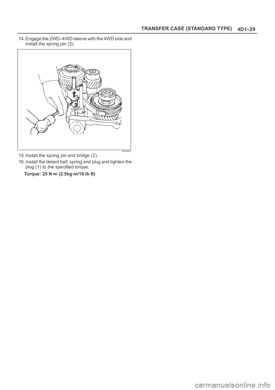
14. Engage the 2WD–4WD sleeve with the 4WD side and
install the spring pin (3).
262RW022
15. Install the spring pin and bridge (2).
16. Install the detent ball, spring and plug and tighten the
plug (1) to the specified torque.
Torque: 25 Nꞏm (2.5kgꞏm/18 lb ft)
Page 4291 of 6000
4D1–30
TRANSFER CASE (STANDARD TYPE)
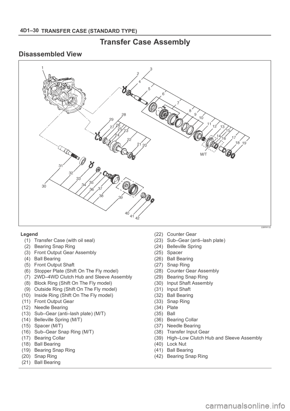
Transfer Case Assembly
Disassembled View
226RW132
Legend
(1) Transfer Case (with oil seal)
(2) Bearing Snap Ring
(3) Front Output Gear Assembly
(4) Ball Bearing
(5) Front Output Shaft
(6) Stopper Plate (Shift On The Fly model)
(7) 2WD–4WD Clutch Hub and Sleeve Assembly
(8) Block Ring (Shift On The Fly model)
(9) Outside Ring (Shift On The Fly model)
(10) Inside Ring (Shift On The Fly model)
(11) Front Output Gear
(12) Needle Bearing
(13) Sub–Gear (anti–lash plate) (M/T)
(14) Belleville Spring (M/T)
(15) Spacer (M/T)
(16) Sub–Gear Snap Ring (M/T)
(17) Bearing Collar
(18) Ball Bearing
(19) Bearing Snap Ring
(20) Snap Ring
(21) Ball Bearing(22) Counter Gear
(23) Sub–Gear (anti–lash plate)
(24) Belleville Spring
(25) Spacer
(26) Ball Bearing
(27) Snap Ring
(28) Counter Gear Assembly
(29) Bearing Snap Ring
(30) Input Shaft Assembly
(31) Input Shaft
(32) Ball Bearing
(33) Snap Ring
(34) Plate
(35) Ball
(36) Bearing Collar
(37) Needle Bearing
(38) Transfer Input Gear
(39) High–Low Clutch Hub and Sleeve Assembly
(40) Lock Nut
(41) Ball Bearing
(42) Bearing Snap Ring
Page 4293 of 6000
4D1–32
TRANSFER CASE (STANDARD TYPE)
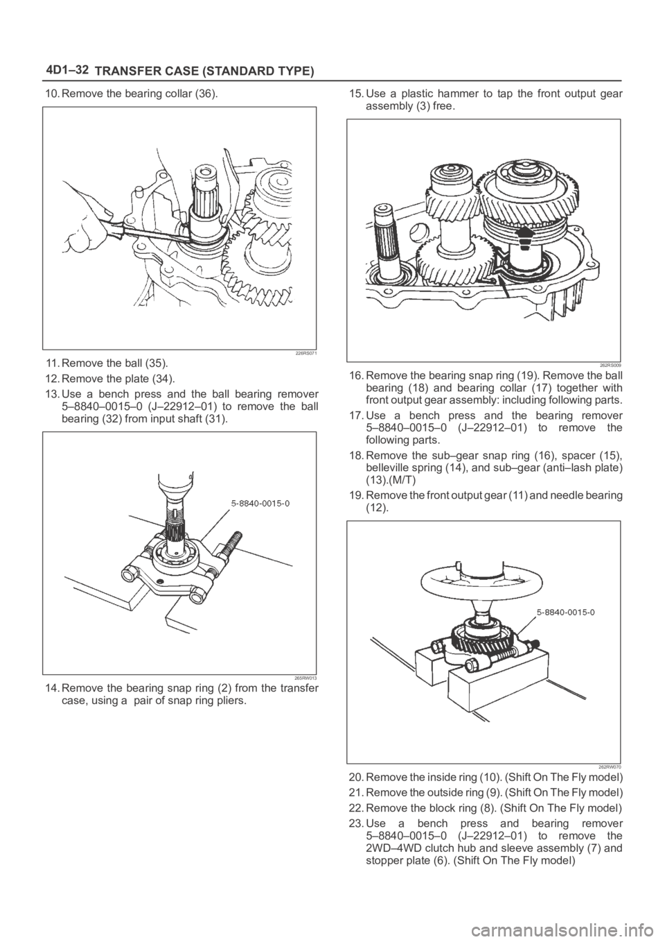
10. Remove the bearing collar (36).
226RS071
11. Remove the ball (35).
12. Remove the plate (34).
13. Use a bench press and the ball bearing remover
5–8840–0015–0 (J–22912–01) to remove the ball
bearing (32) from input shaft (31).
265RW013
14. Remove the bearing snap ring (2) from the transfer
case, using a pair of snap ring pliers.15. Use a plastic hammer to tap the front output gear
assembly (3) free.
262RS009
16. Remove the bearing snap ring (19). Remove the ball
bearing (18) and bearing collar (17) together with
front output gear assembly: including following parts.
17. Use a bench press and the bearing remover
5–8840–0015–0 (J–22912–01) to remove the
following parts.
18. Remove the sub–gear snap ring (16), spacer (15),
belleville spring (14), and sub–gear (anti–lash plate)
(13).(M/T)
19. Remove the front output gear (11) and needle bearing
(12).
262RW070
20. Remove the inside ring (10). (Shift On The Fly model)
2 1 . R e m o v e t h e o u t s i d e r i n g ( 9 ) . ( S h i f t O n T h e F l y m o d e l )
22. Remove the block ring (8). (Shift On The Fly model)
23. Use a bench press and bearing remover
5–8840–0015–0 (J–22912–01) to remove the
2WD–4WD clutch hub and sleeve assembly (7) and
stopper plate (6). (Shift On The Fly model)
Page 4294 of 6000
TRANSFER CASE (STANDARD TYPE)
4D1–33
NOTE: Do not reuse the stopper plate. (Shift On The Fly
model)
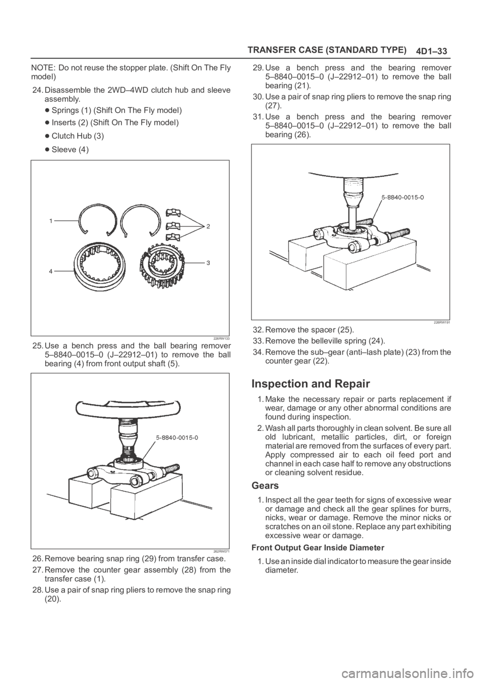
24. Disassemble the 2WD–4WD clutch hub and sleeve
assembly.
Springs (1) (Shift On The Fly model)
Inserts (2) (Shift On The Fly model)
Clutch Hub (3)
Sleeve (4)
226RW133
25. Use a bench press and the ball bearing remover
5–8840–0015–0 (J–22912–01) to remove the ball
bearing (4) from front output shaft (5).
262RW071
26. Remove bearing snap ring (29) from transfer case.
27. Remove the counter gear assembly (28) from the
transfer case (1).
28. Use a pair of snap ring pliers to remove the snap ring
(20).29. Use a bench press and the bearing remover
5–8840–0015–0 (J–22912–01) to remove the ball
bearing (21).
30. Use a pair of snap ring pliers to remove the snap ring
(27).
31. Use a bench press and the bearing remover
5–8840–0015–0 (J–22912–01) to remove the ball
bearing (26).
226RW191
32. Remove the spacer (25).
33. Remove the belleville spring (24).
34. Remove the sub–gear (anti–lash plate) (23) from the
counter gear (22).
Inspection and Repair
1. Make the necessary repair or parts replacement if
wear, damage or any other abnormal conditions are
found during inspection.
2. Wash all parts thoroughly in clean solvent. Be sure all
old lubricant, metallic particles, dirt, or foreign
material are removed from the surfaces of every part.
Apply compressed air to each oil feed port and
channel in each case half to remove any obstructions
or cleaning solvent residue.
Gears
1. Inspect all the gear teeth for signs of excessive wear
or damage and check all the gear splines for burrs,
nicks, wear or damage. Remove the minor nicks or
scratches on an oil stone. Replace any part exhibiting
excessive wear or damage.
Front Output Gear Inside Diameter
1. Use an inside dial indicator to measure the gear inside
diameter.
Page 4296 of 6000
TRANSFER CASE (STANDARD TYPE)
4D1–35
Limit : 3.0 mm (0.118 in)
226RS037
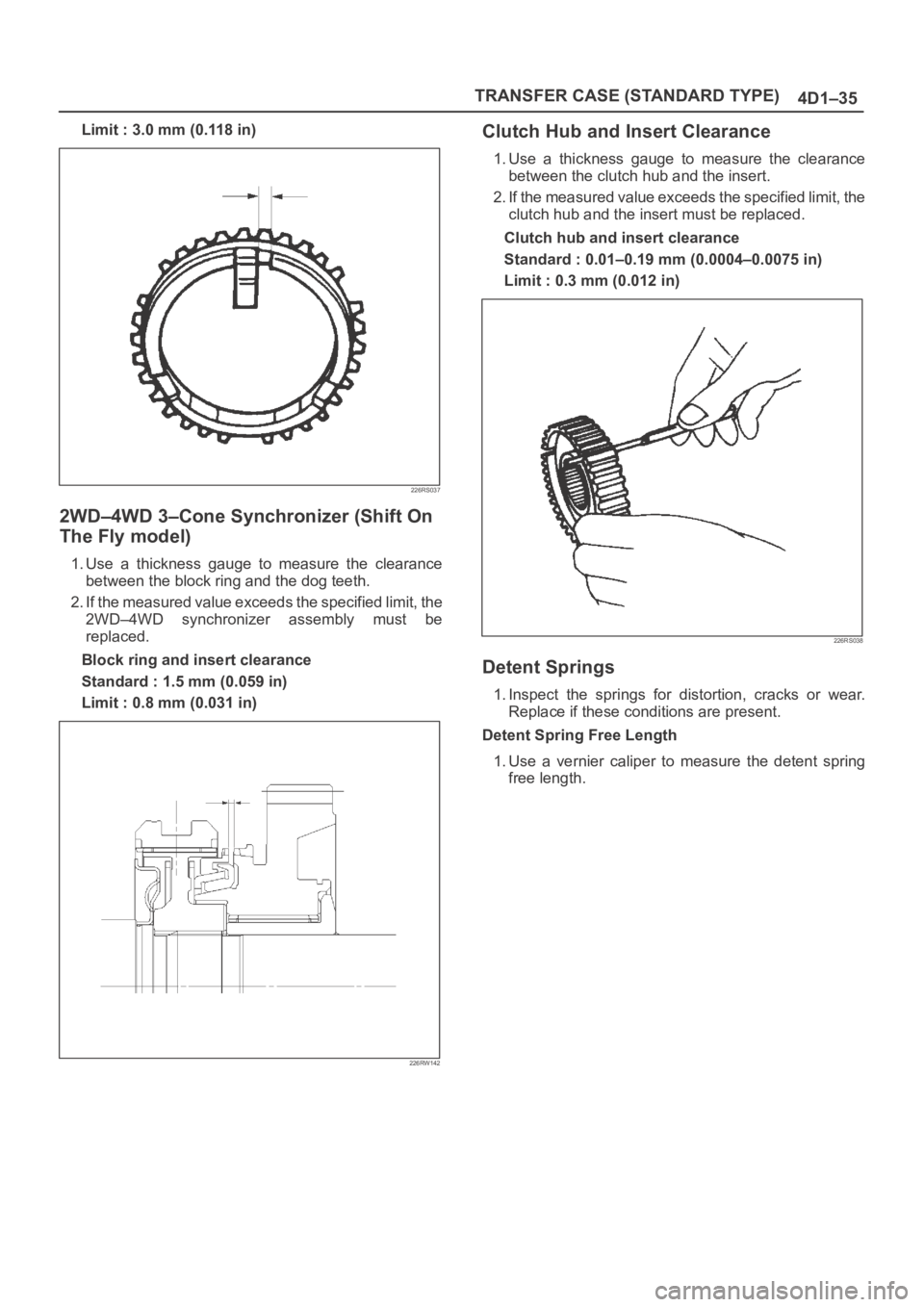
2WD–4WD 3–Cone Synchronizer (Shift On
The Fly model)
1. Use a thickness gauge to measure the clearance
between the block ring and the dog teeth.
2. If the measured value exceeds the specified limit, the
2WD–4WD synchronizer assembly must be
replaced.
Block ring and insert clearance
Standard : 1.5 mm (0.059 in)
Limit : 0.8 mm (0.031 in)
226RW142
Clutch Hub and Insert Clearance
1. Use a thickness gauge to measure the clearance
between the clutch hub and the insert.
2. If the measured value exceeds the specified limit, the
clutch hub and the insert must be replaced.
Clutch hub and insert clearance
Standard : 0.01–0.19 mm (0.0004–0.0075 in)
Limit : 0.3 mm (0.012 in)
226RS038
Detent Springs
1. Inspect the springs for distortion, cracks or wear.
Replace if these conditions are present.
Detent Spring Free Length
1. Use a vernier caliper to measure the detent spring
free length.
Page 4300 of 6000
TRANSFER CASE (STANDARD TYPE)
4D1–39
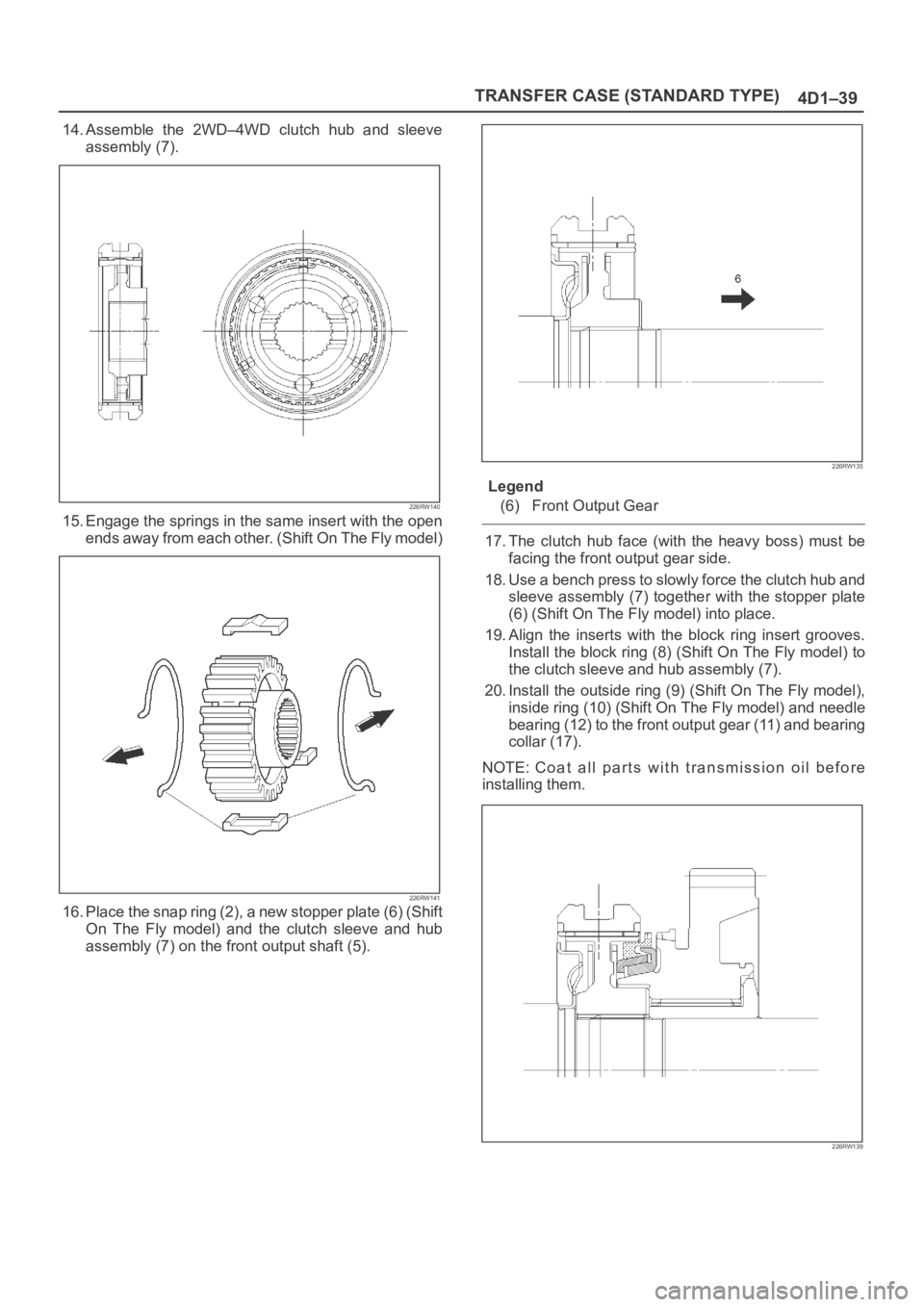
14. Assemble the 2WD–4WD clutch hub and sleeve
assembly (7).
226RW140
15. Engage the springs in the same insert with the open
ends away from each other. (Shift On The Fly model)
226RW141
16. Place the snap ring (2), a new stopper plate (6) (Shift
On The Fly model) and the clutch sleeve and hub
assembly (7) on the front output shaft (5).
226RW135
Legend
(6) Front Output Gear
17. The clutch hub face (with the heavy boss) must be
facing the front output gear side.
18. Use a bench press to slowly force the clutch hub and
sleeve assembly (7) together with the stopper plate
(6) (Shift On The Fly model) into place.
19. Align the inserts with the block ring insert grooves.
Install the block ring (8) (Shift On The Fly model) to
the clutch sleeve and hub assembly (7).
20. Install the outside ring (9) (Shift On The Fly model),
inside ring (10) (Shift On The Fly model) and needle
bearing (12) to the front output gear (11) and bearing
collar (17).
NOTE: Coat all parts with transmission oil before
installing them.
226RW139
Page 4304 of 6000
TRANSFER CASE (STANDARD TYPE)
4D1–43
Main Data and Specifications
General Specifications
Ty p eW/Shift On The Fly System model
Synchronized type gears shifting between the 2 and 4 wheel drive mode.
Constant mesh type gears shifting between “low” and “high”.
WO/Shift On The Fly System model
Constant mesh type gears shifting between the 2 and 4 wheel drive mode,
and between “low” and “high”.
Control methodW/4WD Switch model
Electric control with the button switch on the instrument panel for gear
shifting between the 2 and 4 wheel drive mode.
Remote control with the gear shift lever on the floor for gear shifting
between “low and high” .
WO/4WD Switch model
Remote control with the gear shift lever on the floor for gear shifting.
Gear ratioHigh; 1.000
Low; 2.050
Oil capacity1.45 lit. (1.53 U.S. quart)
Type of lubricantEngine oil
Refer to chart in Section 0
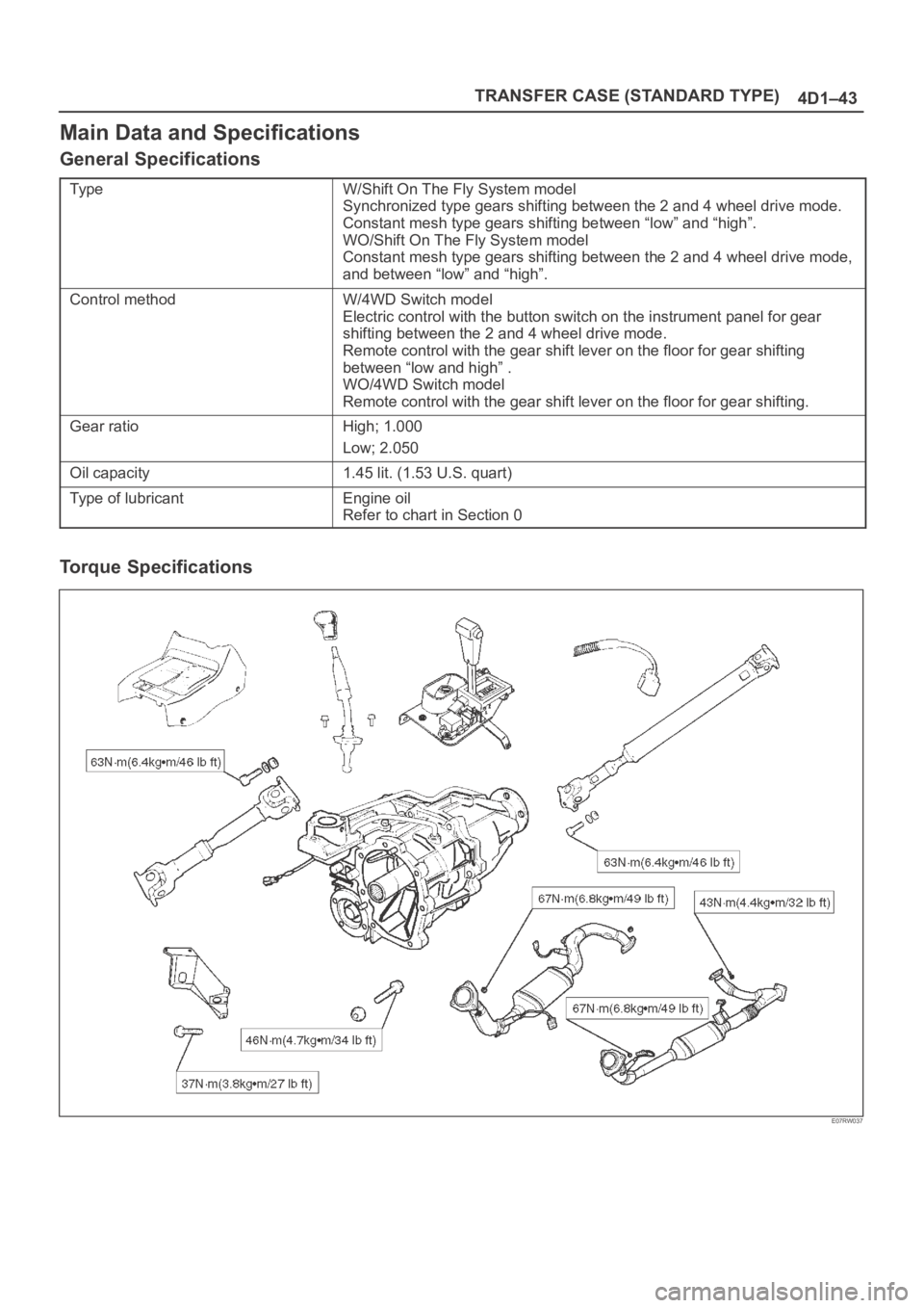
Torque Specifications
E07RW037
Page 4354 of 6000
5A–4
BRAKE CONTROL SYSTEM
normal braking when a malfunction has occurred in the
ABS.
The EHCU has a self-diagnosing function which can
indicate faulty circuits during diagnosis.
The EHCU is mounted on the engine compartment front
right side. It consists of a Motor, Plunger Pump, Solenoid
Valves and Check Valve.
On the outside, the relay box containing a motor relay and
a valve relay is installed.
Solenoid Valves: Reduces or holds the caliper fluid
pressure for each front disc brake or both rear disc brakes
according to the signal sent from the EHCU.
Reservoir: Temporarily holds the brake fluid that returns
from the front and rear disc brake caliper so that pressure
of front disc brake caliper can be reduced smoothly.
Plunger Pump: Feeds the brake fluid held in the reservoir
to the master cylinder.
Motor: Drives the pump according to the signal from
EHCU.
Check Valve: Controls the brake fluid flow.
ABS Warning Light
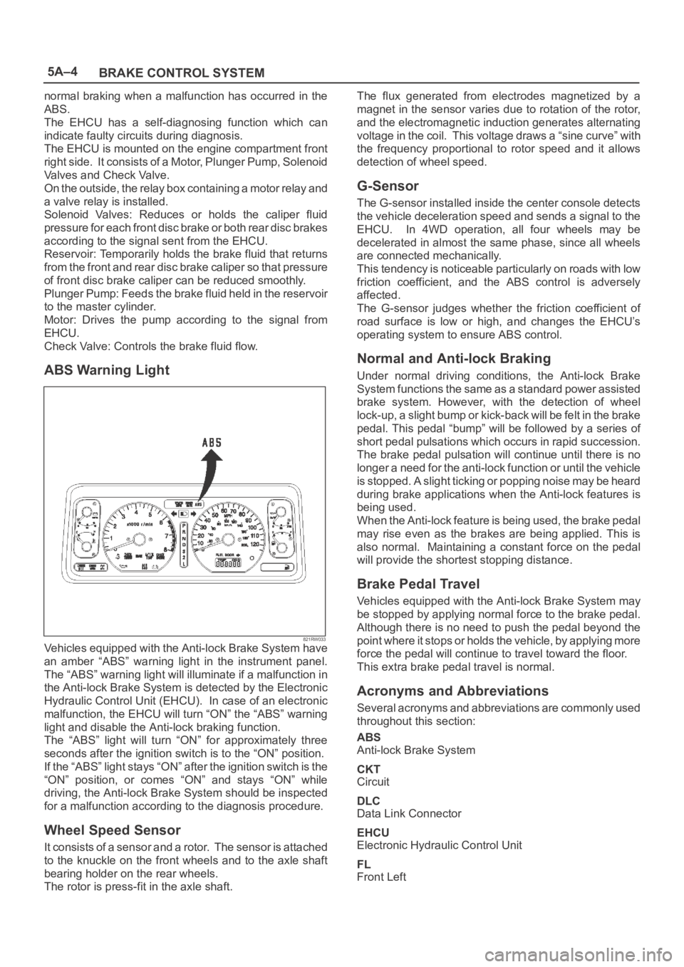
821RW033Vehicles equipped with the Anti-lock Brake System have
an amber “ABS” warning light in the instrument panel.
The “ABS” warning light will illuminate if a malfunction in
the Anti-lock Brake System is detected by the Electronic
Hydraulic Control Unit (EHCU). In case of an electronic
malfunction, the EHCU will turn “ON” the “ABS” warning
light and disable the Anti-lock braking function.
The “ABS” light will turn “ON” for approximately three
seconds after the ignition switch is to the “ON” position.
If the “ABS” light stays “ON” after the ignition switch is the
“ON” position, or comes “ON” and stays “ON” while
driving, the Anti-lock Brake System should be inspected
for a malfunction according to the diagnosis procedure.
Wheel Speed Sensor
It consists of a sensor and a rotor. The sensor is attached
to the knuckle on the front wheels and to the axle shaft
bearing holder on the rear wheels.
The rotor is press-fit in the axle shaft.The flux generated from electrodes magnetized by a
magnet in the sensor varies due to rotation of the rotor,
and the electromagnetic induction generates alternating
voltage in the coil. This voltage draws a “sine curve” with
the frequency proportional to rotor speed and it allows
detection of wheel speed.
G-Sensor
The G-sensor installed inside the center console detects
the vehicle deceleration speed and sends a signal to the
EHCU. In 4WD operation, all four wheels may be
decelerated in almost the same phase, since all wheels
are connected mechanically.
This tendency is noticeable particularly on roads with low
friction coefficient, and the ABS control is adversely
affected.
The G-sensor judges whether the friction coefficient of
road surface is low or high, and changes the EHCU’s
operating system to ensure ABS control.
Normal and Anti-lock Braking
Under normal driving conditions, the Anti-lock Brake
System functions the same as a standard power assisted
brake system. However, with the detection of wheel
lock-up, a slight bump or kick-back will be felt in the brake
pedal. This pedal “bump” will be followed by a series of
short pedal pulsations which occurs in rapid succession.
The brake pedal pulsation will continue until there is no
longer a need for the anti-lock function or until the vehicle
is stopped. A slight ticking or popping noise may be heard
during brake applications when the Anti-lock features is
being used.
When the Anti-lock feature is being used, the brake pedal
may rise even as the brakes are being applied. This is
also normal. Maintaining a constant force on the pedal
will provide the shortest stopping distance.
Brake Pedal Travel
Vehicles equipped with the Anti-lock Brake System may
be stopped by applying normal force to the brake pedal.
Although there is no need to push the pedal beyond the
point where it stops or holds the vehicle, by applying more
force the pedal will continue to travel toward the floor.
This extra brake pedal travel is normal.
Acronyms and Abbreviations
Several acronyms and abbreviations are commonly used
throughout this section:
ABS
Anti-lock Brake System
CKT
Circuit
DLC
Data Link Connector
EHCU
Electronic Hydraulic Control Unit
FL
Front Left
Page 4357 of 6000
5A–7 BRAKE CONTROL SYSTEM
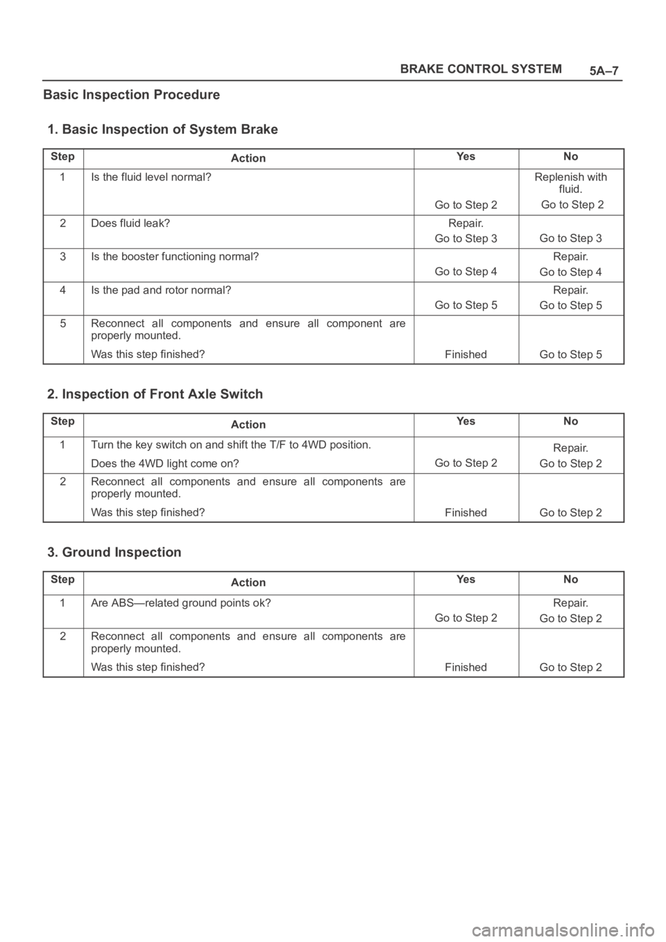
Basic Inspection Procedure
1. Basic Inspection of System Brake
StepActionYe sNo
1Is the fluid level normal?
Go to Step 2
Replenish with
fluid.
Go to Step 2
2Does fluid leak?Repair.
Go to Step 3
Go to Step 3
3Is the booster functioning normal?
Go to Step 4
Repair.
Go to Step 4
4Is the pad and rotor normal?
Go to Step 5
Repair.
Go to Step 5
5Reconnect all components and ensure all component are
properly mounted.
Was this step finished?
FinishedGo to Step 5
2. Inspection of Front Axle Switch
StepActionYe sNo
1Turn the key switch on and shift the T/F to 4WD position.
Does the 4WD light come on?
Go to Step 2
Repair.
Go to Step 2
2Reconnect all components and ensure all components are
properly mounted.
Was this step finished?
FinishedGo to Step 2
3. Ground Inspection
StepActionYe sNo
1Are ABS—related ground points ok?
Go to Step 2
Repair.
Go to Step 2
2Reconnect all components and ensure all components are
properly mounted.
Was this step finished?
FinishedGo to Step 2