engine oil OPEL FRONTERA 1998 Workshop Manual
[x] Cancel search | Manufacturer: OPEL, Model Year: 1998, Model line: FRONTERA, Model: OPEL FRONTERA 1998Pages: 6000, PDF Size: 97 MB
Page 1486 of 6000

6G–7 ENGINE LUBRICATION
Oil Pan and Crankcase
Removal
1. Disconnect battery ground cable.
2. Drain engine oil.
3. Lift vehicle by supporting the frame.
4. Remove front wheels.
5. Remove oil level dipstick from level gauge tube.
6. Remove stone guard.
7. Remove radiator under fan shroud.
8. Remove suspension cross member fixing bolts, 2 pcs
each per side and remove suspension cross member.
9. Remove pitman arm and relay lever assembly, using
the 5–8840–2005–0 remover, remove pitman arm
from the steering unit and remove four fixing bolts for
relay lever assembly.
10. Remove axle housing assembly four fixing bolts from
housing isolator side and mounting bolts from wheel
side. At this time support the axle with a garage jack
and remove axle housing assembly.
11. Remove oil pan fixing bolts.
12. Remove oil pan, using 5–8840–2153–0 sealer cutter,
remove oil pan.
013RS003
13. Remove crankcase fixing bolts.
14. Remove crankcase, using 5–8840–2153–0 sealer
cutter, remove crankcase.
NOTE: Do not deform or damage the flange of oil pan and
crankcase.
Replace the oil pan and/or crankcase if deformed or dam-
aged.
013RS003
Installation
1. Install crankcase.
1. Remove residual sealant, lubricant and moisture
from mounting surface, then dry thoroughly.
2. Properly apply a 4.5 mm (0.7 in) wide bead of
sealant (TB-1207C or equivalent) to mounting
surface of crankcase.
Sealant beat must be continuous.
The crankcase must be installed within 5
minutes after sealant application before the
sealant hardens.
013RW010
Page 1487 of 6000

6G–8
ENGINE LUBRICATION
3. Install crankcase, tighten crankcase fixing bolts
to the specified torque.
Torque : 10 Nꞏm (1.0 Kgꞏm/89 lb in)
013RW004
2. Install oil pan
1. Remove residual sealant, lubricant and moisture
from mounting surface, then dry thoroughly.
2. Properly apply a 4.5 mm (07 in) wide bead of
sealant (TB-1207C or equivalent) to mounting
surface of oil pan.
Sealant beat must be continuous.
The crankcase must be installed within 5
minutes after sealant application befor the
sealant hardens.
013RW003
3. Install oil pan, tighten oil pan fixing bolts to the
specified torque.
Torque : 25 Nꞏm (2.5 Kgꞏm/18 lb ft)3. Install axle housing assembly and tighten fixing bolts
to the specified torque.
Axle case bolts
Torque : 82 Nꞏm (8.4 Kgꞏm/60 lb ft)
Mounting bolts
Torque : 152 Nꞏm (15.5 Kgꞏm/112 lb ft)
013RW005
4. Install relay lever assembly and tighten fixing bolts.
Torque: 44 Nꞏm (4.5 Kgꞏm/32 lb ft)
5. Engage teeth of pitman arm and steering unit, and
tighten nut to the specified torque.
Torque : 216 Nꞏm (22.0 Kgꞏm/159 lb ft)
013RW006
Legend
(1) Pitman Arm
(2) Relay Lever
Page 1488 of 6000

6G–9 ENGINE LUBRICATION
6. Install suspension cross member and tighten fixing
bolts to the specified torque.
Torque : 78 Nꞏm (8.0 Kgꞏm/58 lb ft)
013RW007
7. Install radiator under fan shroud.
8. Install stone guard.
9. Install engine oil level dipstick.
10. Fill engine oil until full level on engine oil gauge
dipstick.
Page 1489 of 6000

6G–10
ENGINE LUBRICATION
Oil Pump
Removal
1. Disconnect battery ground cable.
2. Drain engine oil.
3. Remove crankcase assembly.
Refer to removal procedure for Oil Pan and
Crankcase in this manual.
4. Remove crankshaft pulley.
Refer to removal procedure for Crankshaft Pulley in
this manual.
5. Remove timing belt.
Refer to removal procedure for Timing Belt in this
manual.
6. Remove timing pulley from crankshaft.
7. Remove four fixing bolts from oil filter assembly.
8. Remove oil strainer fixing bolts, remove oil strainer
assembly with O-ring.
9. Remove three bolts from oil pipe and O-ring.
10. Remove eight oil pump fixing bolts, then oil pump
assembly.
11. Remove sealant from mounting surface of oil pump
assembly, cylinder block and take care not to damage
mounting surfaces of oil pump and cylinder block.
Installation
1. Install oil pump assembly
Apply sealant (TB-1207B or equivalent) to the oil
pump mounting surfaces as shown in the
illustration.
The oil pump assembly must be installed within 5
minutes after sealant application before the sealant
hardens.
NOTE: Do not apply sealant to the oil ports.
051RW002
Use 5–8840–2287–0 installer when installing new
oil seal.
Apply engine oil to oil seal lip.
Install oil pump assembly to the cylinder block.
NOTE: Do not damage oil seal during installation of oil
pump assembly.
015RS001
Tighten fixing bolts to the specified torque.
Torque : 25 Nꞏm (2.5 Kgꞏm/18 lb ft)
051RW001
2. Install oil pipe with O-ring, tighten fixing bolt to the
specified torque.
Torque : 10 Nꞏm (1.0 Kgꞏm/89 lb in)
3. Install oil strainer with O-ring, tighten fixing bolt to the
specified torque.
Torque : 25 Nꞏm (2.5 Kgꞏm/18 lb ft)
Page 1490 of 6000

6G–11 ENGINE LUBRICATION
4. Install oil filter assembly and tighten bolts to the
specified torque.
Torque : 25 Nꞏm (2.5 Kgꞏm/18 lb ft)
050RW001
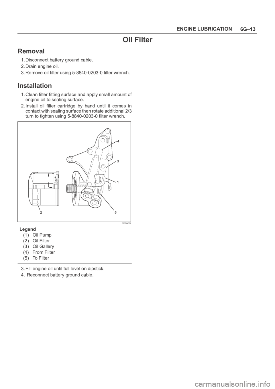
Legend
(1) Oil Pump
(2) Oil Filter
(3) Oil Gallery
(4) From Oil Filter
(5) To Oil Filter
5. Install timing pulley on crankshaft.
Install timing belt.
Refer to installation procedure for Timing Belt in this
manual.
6. Install crankshaft pulley.
Refer to install procedure for Crankshaft Pulley in
this manual.
7. Install crankcase assembly.
Refer to installation procedure for Oil Pan and
Crankcase in this manual.
8. Refill engine oil until full level on engine oil dipstick.
Page 1491 of 6000

6G–12
ENGINE LUBRICATION
Oil Pump Oil Seal
Removal
1. Disconnect battery ground cable.
2. Drain engine oil.
3. Remove crankshaft pulley.
Refer to removal procedure for Crankshaft Pulley in
this manual.
4. Remove timing belt.
Refer to removal procedure for Timing Belt in this
manual.
5. Remove timing pulley from crankshaft.
6. Remove oil pump oil seal using a sealer puller.
NOTE: Take care not to damage sealing surfaces of oil
pump and crankshaft when removing oil seal.
Installation
1. Install oil pump oil seal, apply engine oil to oil seal lip,
then install oil seal using 5–8840–2287–0 installer.
015RS001
2. Install timing pulley to crankshaft.
3. Install timing belt.
Refer to installation procedure for Timing Belt in this
manual.
4. Install crankshaft pulley.
Refer to installation procedure for Crankshaft
Pulley in this manual.
5. Refill engine oil until full level.
Page 1492 of 6000

6G–13 ENGINE LUBRICATION
Oil Filter
Removal
1. Disconnect battery ground cable.
2. Drain engine oil.
3. Remove oil filter using 5-8840-0203-0 filter wrench.
Installation
1. Clean filter fitting surface and apply small amount of
engine oil to sealing surface.
2. Install oil filter cartridge by hand until it comes in
contact with sealing surface then rotate additional 2/3
turn to tighten using 5-8840-0203-0 filter wrench.
050RW001
Legend
(1) Oil Pump
(2) Oil Filter
(3) Oil Gallery
(4) From Filter
(5) To Filter
3. Fill engine oil until full level on dipstick.
4. Reconnect battery ground cable.
Page 1493 of 6000

6G–14
ENGINE LUBRICATION
Main Data and Specification
General Specification
ItemSpecificationsItem6VD16VE1
Oil capacity5.3 liters
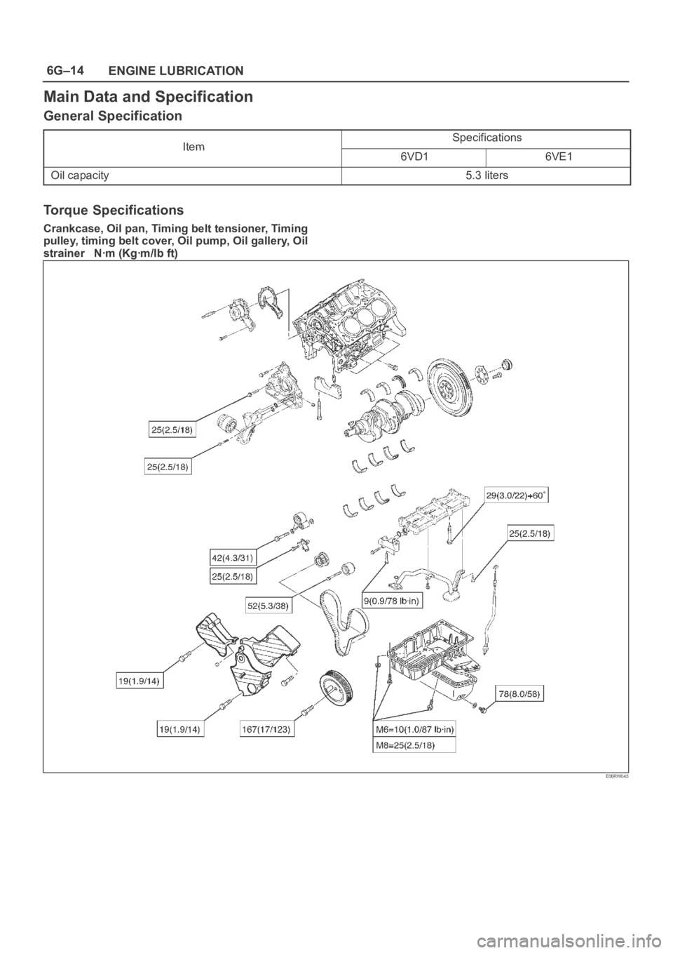
Torque Specifications
Crankcase, Oil pan, Timing belt tensioner, Timing
pulley, timing belt cover, Oil pump, Oil gallery, Oil
strainer Nꞏm (Kgꞏm/lb ft)
E06RW045
Page 1494 of 6000

6G–15 ENGINE LUBRICATION
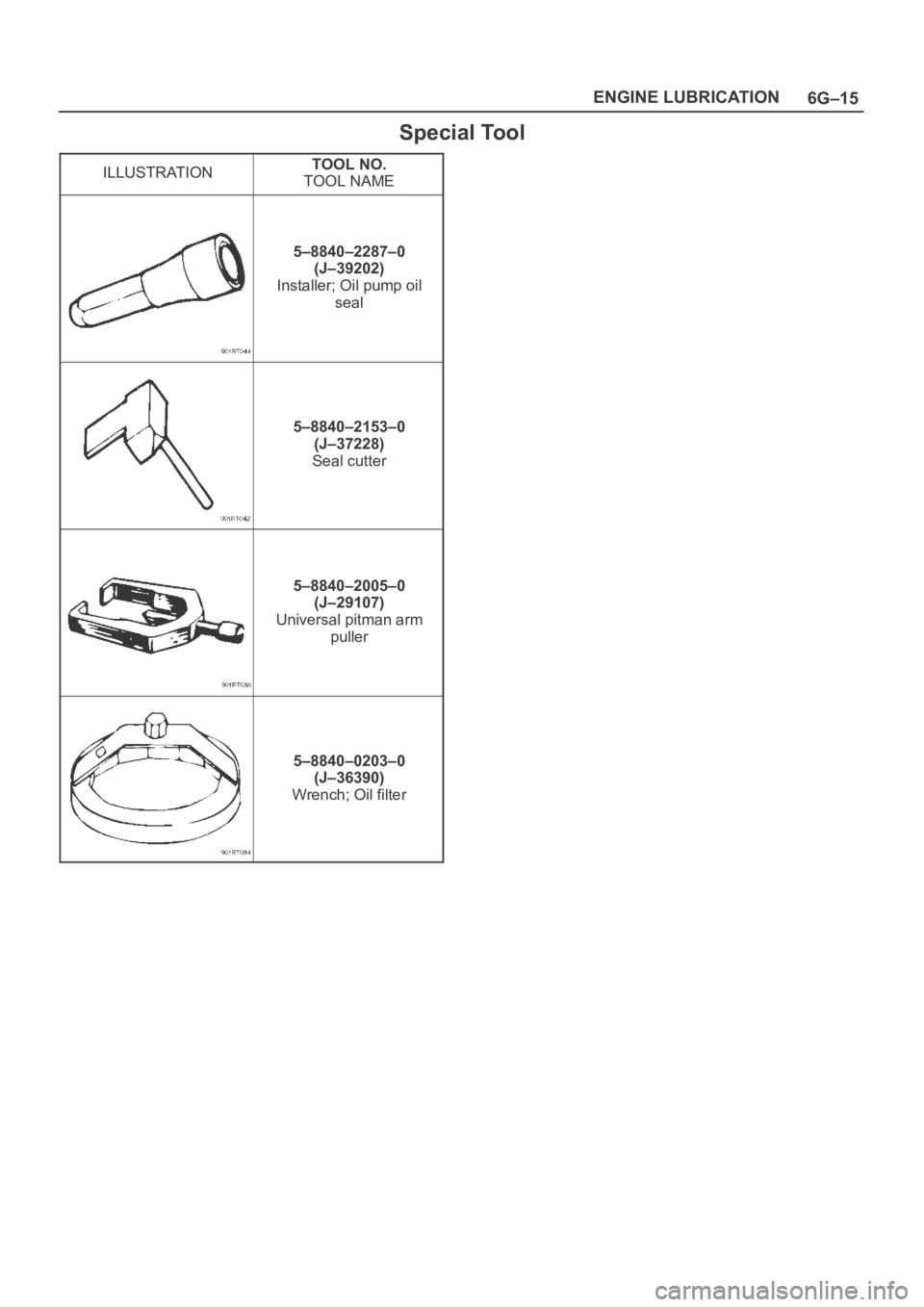
Special Tool
ILLUSTRATIONTOOL NO.
TOOL NAME
5–8840–2287–0
(J–39202)
Installer; Oil pump oil
seal
5–8840–2153–0
(J–37228)
Seal cutter
5–8840–2005–0
(J–29107)
Universal pitman arm
puller
5–8840–0203–0
(J–36390)
Wrench; Oil filter
Page 1734 of 6000

ENGINE MECHANICAL 6A – 1
ENGINE
ENGINE MECHANICAL
CONTENTS
General Description . . . . . . . . . . . . . . . . . . . . 6A–2
Service Information . . . . . . . . . . . . . . . . . . . . 6A–3
Service Standard . . . . . . . . . . . . . . . . . . . . . . 6A–6
Servicing . . . . . . . . . . . . . . . . . . . . . . . . . . . . 6A–9
Tightening Torque . . . . . . . . . . . . . . . . . . . . . 6A–14
Special Tools . . . . . . . . . . . . . . . . . . . . . . . . . 6A–25
Engine Assembly . . . . . . . . . . . . . . . . . . . . . . 6A–28
Engine Mount (RH) . . . . . . . . . . . . . . . . . . . . 6A–30
Engine Mount (LH). . . . . . . . . . . . . . . . . . . . . 6A–31
Intercooler . . . . . . . . . . . . . . . . . . . . . . . . . . . 6A–32
Cylinder Head Cover . . . . . . . . . . . . . . . . . . . 6A–33
Intake Manifold . . . . . . . . . . . . . . . . . . . . . . . 6A–35
Exhaust Manifold . . . . . . . . . . . . . . . . . . . . . . 6A–36
Turbocharger . . . . . . . . . . . . . . . . . . . . . . . . . 6A–38Cylinder Head . . . . . . . . . . . . . . . . . . . . . . . . 6A–41
Cylinder Head Gasket . . . . . . . . . . . . . . . . . . 6A–43
Camshaft . . . . . . . . . . . . . . . . . . . . . . . . . . . . 6A–47
Timing Gear . . . . . . . . . . . . . . . . . . . . . . . . . . 6A–52
Valve Stem Seal, Valve Spring and Adjuster . . 6A–60
Valve Clearance Adjustment. . . . . . . . . . . . . . 6A–67
Oil Rail and Injector . . . . . . . . . . . . . . . . . . . . 6A–69
Crank Case . . . . . . . . . . . . . . . . . . . . . . . . . . 6A–72
Crankshaft . . . . . . . . . . . . . . . . . . . . . . . . . . . 6A–74
Piston and Connecting Rod . . . . . . . . . . . . . . 6A–84
Cylinder Block . . . . . . . . . . . . . . . . . . . . . . . . 6A–92
Oil Pump Assembly . . . . . . . . . . . . . . . . . . . . 6A–98
Oil Filter Cartridge . . . . . . . . . . . . . . . . . . . . . 6A–99
Oil Cooler . . . . . . . . . . . . . . . . . . . . . . . . . . . 6A–99