ignition OPEL FRONTERA 1998 User Guide
[x] Cancel search | Manufacturer: OPEL, Model Year: 1998, Model line: FRONTERA, Model: OPEL FRONTERA 1998Pages: 6000, PDF Size: 97 MB
Page 819 of 6000

5A–9 BRAKE CONTROL SYSTEM
Getting Started
Before operating the Isuzu PCMCIA card with the
Tech 2, the following steps must be performed:
1. The Isuzu 98 System PCMCIA card (1) inserts into
the Tech 2 (4).
2. Connect the SAE 16/19 adapter (2) to the DLC cable
(3).
3. Connect the DLC cable to the Tech 2 (4).
4. Make sure the vehicle ignition is off.
5. Connect the Tech 2 SAE 16/19 adapter to the vehicle
DLC connector.
350RV014
6. The vehicle ignition turns on.
7. Power up the Tech 2.8. Verify the Tech 2 power up display.
060RW009
Page 822 of 6000
5A–12
BRAKE CONTROL SYSTEM
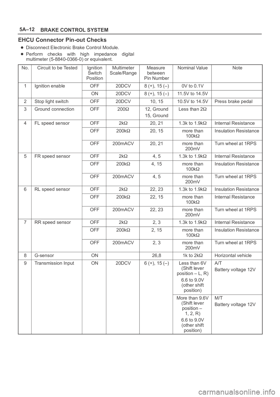
EHCU Connector Pin-out Checks
Disconnect Electronic Brake Control Module.
Perform checks with high impedance digital
multimeter (5-8840-0366-0) or equivalent.
No.
Circuit to be TestedIgnition
Switch
PositionMultimeter
Scale/RangeMeasure
between
Pin NumberNominal ValueNote
1Ignition enableOFF20DCV8 (+), 15 (–)0V to 0.1V
ON20DCV8 (+), 15 (–)11.5V to 14.5V
2Stop light switchOFF20DCV10, 1510.5V to 14.5VPress brake pedal
3Ground connectionOFF20012, Ground
15, GroundLess than 2
4FL speed sensorOFF2k20, 211.3k to 1.9kInternal Resistance
OFF200k20, 15more than
100kInsulation Resistance
OFF200mACV20, 21more than
200mVTurn wheel at 1RPS
5FR speed sensorOFF2k4, 51.3k to 1.9kInternal Resistance
OFF200k4, 15more than
100kInsulation Resistance
OFF200mACV4, 5more than
200mVTurn wheel at 1RPS
6RL speed sensorOFF2k22, 231.3k to 1.9kInsulation Resistance
OFF200k22, 15more than
100kInternal Resistance
OFF200mACV22, 23more than
200mVTurn wheel at 1RPS
7RR speed sensorOFF2k2, 31.3k to 1.9kInternal Resistance
OFF200k2, 15more than
100kInsulation Resistance
OFF200mACV2, 3more than
200mVTurn wheel at 1RPS
8G-sensorON26,81k to 2kHorizontal vehicle
9Transmission InputON20DCV6 (+), 15 (–)Less than 6V
(Shift lever
position – L, R)
6.6 to 9.0V
(other shift
position)A/T
Battery voltage 12V
More than 9.6V
(Shift lever
position –
1, 2, R)
6.6 to 9.0V
(other shift
position)M/T
Battery voltage 12V
Page 847 of 6000
5A–37 BRAKE CONTROL SYSTEM
StepNo Ye s
Action
5Is front 4WD controller normal?
Replace EHCU.
Go to Step 9
Replace 4WD
controller or
repair harness.
Go to Step 9
6Is transmission input normal? (Chart C-2 or TC-2)
Go to Step 7
Replace SW or
repair harness
Go to Step 9
7Is front 4WD controller normal?
Go to Step 8
Replace 4WD
controller or
repair harness.
Go to Step 9
8Is hydraulic unit grounded properly?Replace EHCU.
Go to Step 9Correct.
Go to Step 9
9Reconnect all components, ensure all components are properly
mounted.
Was this step finished?Repeat the “Basic
diagnostic flow
chart.”
Go to Step 9
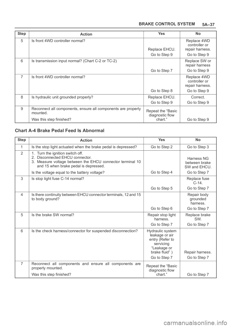
Chart A-4 Brake Pedal Feed Is Abnormal
StepActionYe sNo
1Is the stop light actuated when the brake pedal is depressed?Go to Step 2Go to Step 3
21. Turn the ignition switch off.
2. Disconnected EHCU connector.
3. Measure voltage between the EHCU connector terminal 10
and 15 when brake pedal is depressed.
Is the voltage equal to the battery voltage?
Go to Step 4
Harness NG
between brake
SW and EHCU.
Go to Step 7
3Is stop light fuse C-14 normal?
Go to Step 5
Replace fuse
C-14.
Go to Step 7
4Is there continuity between EHCU connector terminals, 12 and 15
to body ground?
Go to Step 6
Repair body
grounded
harness.
Go to Step 7
5Is the brake SW normal?Repair stop light
harness.
Go to Step 7Replace brake
SW.
Go to Step 7
6Is the check harness/connector for suspended disconnection?Hydraulic system
leakage or air
entry (Refer to
servicing
“Leakage or
brake fluid” )
Go to Step 7
Repair harness.
Go to Step 7
7Reconnect all components and ensure all components are
properly mounted.
Was this step finished?Repeat the “Basic
diagnostic flow
chart.”
Go to Step 7
Page 853 of 6000
5A–43 BRAKE CONTROL SYSTEM
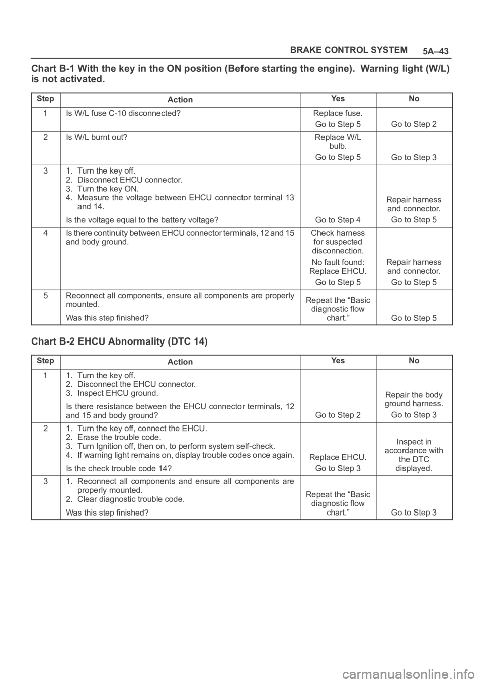
Chart B-1 With the key in the ON position (Before starting the engine). Warning light (W/L)
is not activated.
StepActionYe sNo
1Is W/L fuse C-10 disconnected?Replace fuse.
Go to Step 5
Go to Step 2
2Is W/L burnt out?Replace W/L
bulb.
Go to Step 5
Go to Step 3
31. Turn the key off.
2. Disconnect EHCU connector.
3. Turn the key ON.
4. Measure the voltage between EHCU connector terminal 13
and 14.
Is the voltage equal to the battery voltage?
Go to Step 4
Repair harness
and connector.
Go to Step 5
4Is there continuity between EHCU connector terminals, 12 and 15
and body ground.Check harness
for suspected
disconnection.
No fault found:
Replace EHCU.
Go to Step 5
Repair harness
and connector.
Go to Step 5
5Reconnect all components, ensure all components are properly
mounted.
Was this step finished?Repeat the “Basic
diagnostic flow
chart.”
Go to Step 5
Chart B-2 EHCU Abnormality (DTC 14)
StepActionYe sNo
11. Turn the key off.
2. Disconnect the EHCU connector.
3. Inspect EHCU ground.
Is there resistance between the EHCU connector terminals, 12
and 15 and body ground?
Go to Step 2
Repair the body
ground harness.
Go to Step 3
21. Turn the key off, connect the EHCU.
2. Erase the trouble code.
3. Turn Ignition off, then on, to perform system self-check.
4. If warning light remains on, display trouble codes once again.
Is the check trouble code 14?
Replace EHCU.
Go to Step 3
Inspect in
accordance with
the DTC
displayed.
31. Reconnect all components and ensure all components are
properly mounted.
2. Clear diagnostic trouble code.
Was this step finished?
Repeat the “Basic
diagnostic flow
chart.”
Go to Step 3
Page 862 of 6000
5A–52
BRAKE CONTROL SYSTEM
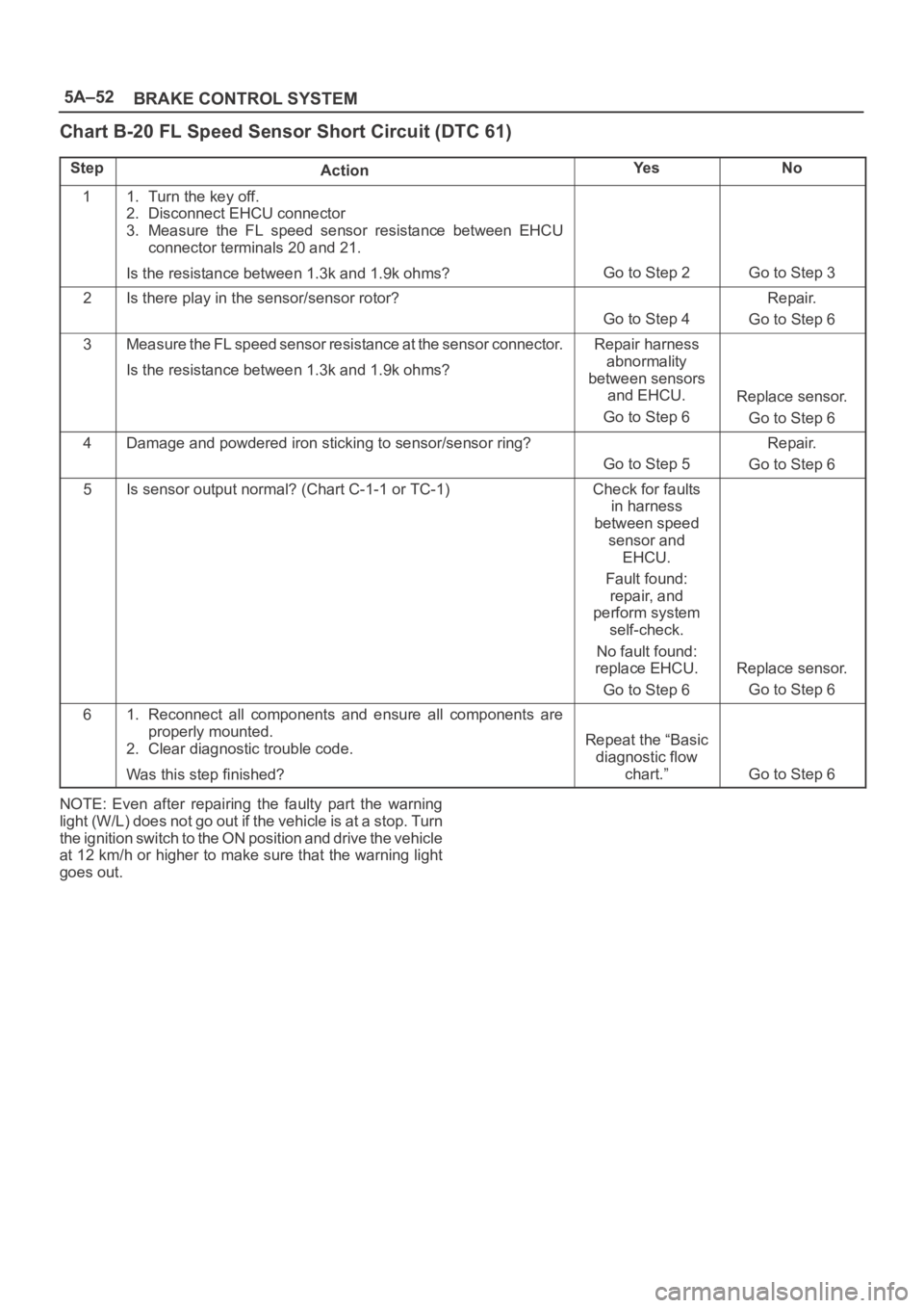
Chart B-20 FL Speed Sensor Short Circuit (DTC 61)
StepActionYe sNo
11. Turn the key off.
2. Disconnect EHCU connector
3. Measure the FL speed sensor resistance between EHCU
connector terminals 20 and 21.
Is the resistance between 1.3k and 1.9k ohms?
Go to Step 2Go to Step 3
2Is there play in the sensor/sensor rotor?
Go to Step 4
Repair.
Go to Step 6
3Measure the FL speed sensor resistance at the sensor connector.
Is the resistance between 1.3k and 1.9k ohms?Repair harness
abnormality
between sensors
and EHCU.
Go to Step 6
Replace sensor.
Go to Step 6
4Damage and powdered iron sticking to sensor/sensor ring?
Go to Step 5
Repair.
Go to Step 6
5Is sensor output normal? (Chart C-1-1 or TC-1)Check for faults
in harness
between speed
sensor and
EHCU.
Fault found:
repair, and
perform system
self-check.
No fault found:
replace EHCU.
Go to Step 6
Replace sensor.
Go to Step 6
61. Reconnect all components and ensure all components are
properly mounted.
2. Clear diagnostic trouble code.
Was this step finished?
Repeat the “Basic
diagnostic flow
chart.”
Go to Step 6
NOTE: Even after repairing the faulty part the warning
light (W/L) does not go out if the vehicle is at a stop. Turn
the ignition switch to the ON position and drive the vehicle
at 12 km/h or higher to make sure that the warning light
goes out.
Page 863 of 6000
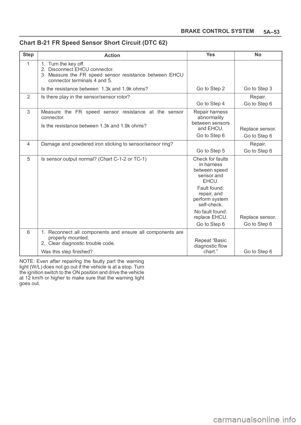
5A–53 BRAKE CONTROL SYSTEM
Chart B-21 FR Speed Sensor Short Circuit (DTC 62)
StepActionYe sNo
11. Turn the key off.
2. Disconnect EHCU connector.
3. Measure the FR speed sensor resistance between EHCU
connector terminals 4 and 5.
Is the resistance between 1.3k and 1.9k ohms?
Go to Step 2Go to Step 3
2Is there play in the sensor/sensor rotor?
Go to Step 4
Repair.
Go to Step 6
3Measure the FR speed sensor resistance at the sensor
connector.
Is the resistance between 1.3k and 1.9k ohms?Repair harness
abnormality
between sensors
and EHCU.
Go to Step 6
Replace sensor.
Go to Step 6
4Damage and powdered iron sticking to sensor/sensor ring?
Go to Step 5
Repair.
Go to Step 6
5Is sensor output normal? (Chart C-1-2 or TC-1)Check for faults
in harness
between speed
sensor and
EHCU.
Fault found:
repair, and
perform system
self-check.
No fault found:
replace EHCU.
Go to Step 6
Replace sensor.
Go to Step 6
61. Reconnect all components and ensure all components are
properly mounted.
2. Clear diagnostic trouble code.
Was this step finished?
Repeat “Basic
diagnostic flow
chart.”
Go to Step 6
NOTE: Even after repairing the faulty part the warning
light (W/L) does not go out if the vehicle is at a stop. Turn
the ignition switch to the ON position and drive the vehicle
at 12 km/h or higher to make sure that the warning light
goes out.
Page 864 of 6000
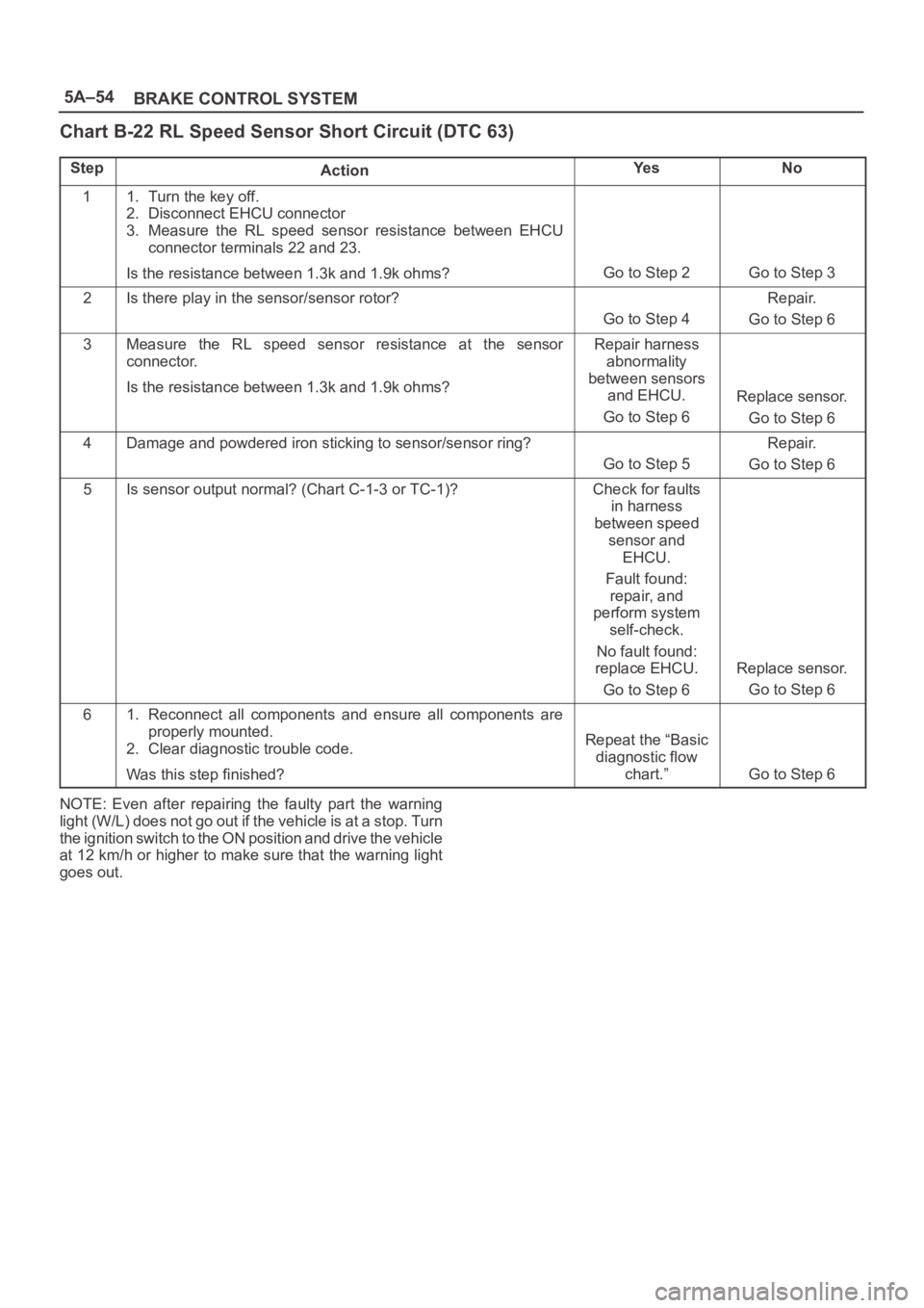
5A–54
BRAKE CONTROL SYSTEM
Chart B-22 RL Speed Sensor Short Circuit (DTC 63)
StepActionYe sNo
11. Turn the key off.
2. Disconnect EHCU connector
3. Measure the RL speed sensor resistance between EHCU
connector terminals 22 and 23.
Is the resistance between 1.3k and 1.9k ohms?
Go to Step 2Go to Step 3
2Is there play in the sensor/sensor rotor?
Go to Step 4
Repair.
Go to Step 6
3Measure the RL speed sensor resistance at the sensor
connector.
Is the resistance between 1.3k and 1.9k ohms?Repair harness
abnormality
between sensors
and EHCU.
Go to Step 6
Replace sensor.
Go to Step 6
4Damage and powdered iron sticking to sensor/sensor ring?
Go to Step 5
Repair.
Go to Step 6
5Is sensor output normal? (Chart C-1-3 or TC-1)?Check for faults
in harness
between speed
sensor and
EHCU.
Fault found:
repair, and
perform system
self-check.
No fault found:
replace EHCU.
Go to Step 6
Replace sensor.
Go to Step 6
61. Reconnect all components and ensure all components are
properly mounted.
2. Clear diagnostic trouble code.
Was this step finished?
Repeat the “Basic
diagnostic flow
chart.”
Go to Step 6
NOTE: Even after repairing the faulty part the warning
light (W/L) does not go out if the vehicle is at a stop. Turn
the ignition switch to the ON position and drive the vehicle
at 12 km/h or higher to make sure that the warning light
goes out.
Page 865 of 6000
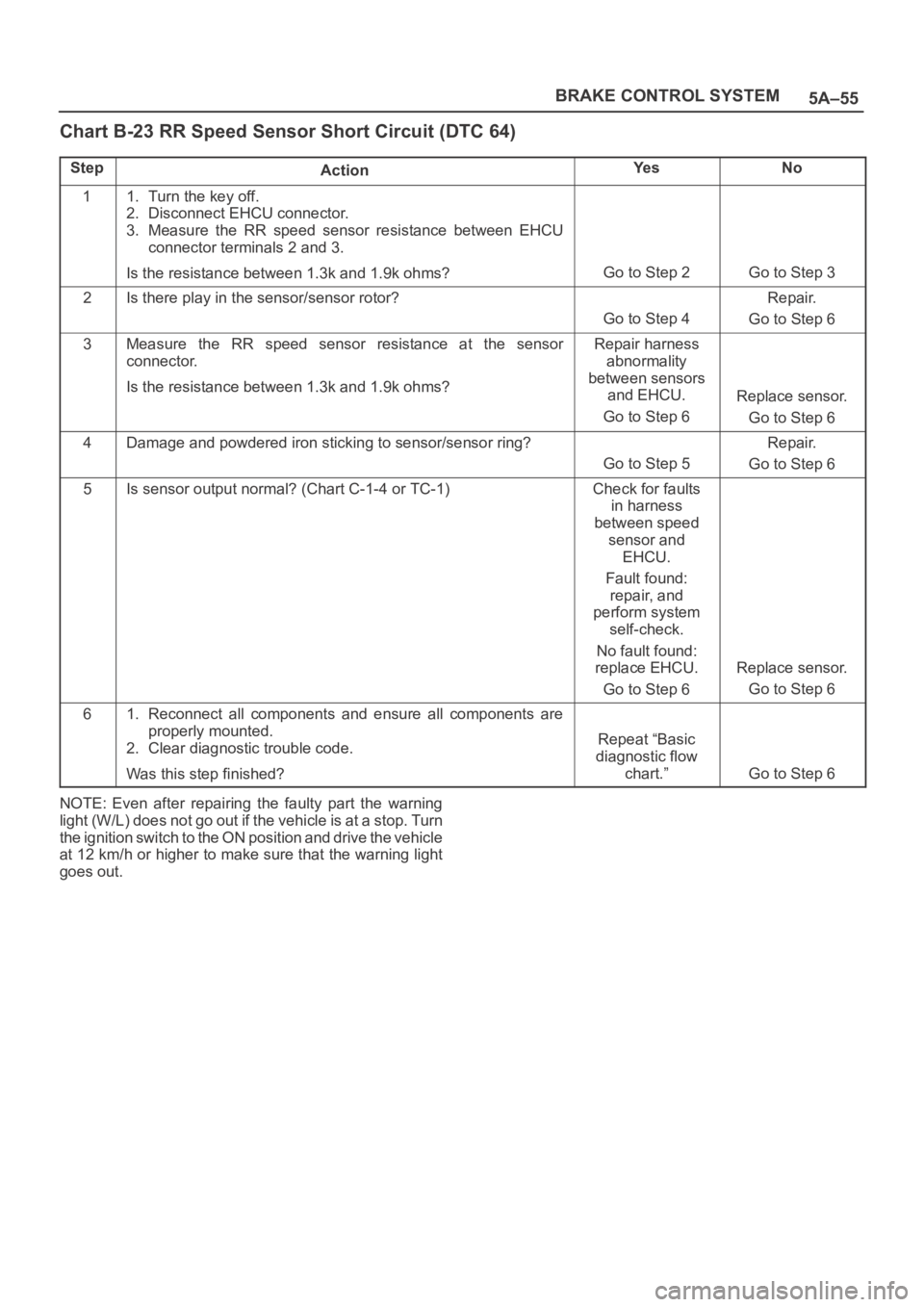
5A–55 BRAKE CONTROL SYSTEM
Chart B-23 RR Speed Sensor Short Circuit (DTC 64)
StepActionYe sNo
11. Turn the key off.
2. Disconnect EHCU connector.
3. Measure the RR speed sensor resistance between EHCU
connector terminals 2 and 3.
Is the resistance between 1.3k and 1.9k ohms?
Go to Step 2Go to Step 3
2Is there play in the sensor/sensor rotor?
Go to Step 4
Repair.
Go to Step 6
3Measure the RR speed sensor resistance at the sensor
connector.
Is the resistance between 1.3k and 1.9k ohms?Repair harness
abnormality
between sensors
and EHCU.
Go to Step 6
Replace sensor.
Go to Step 6
4Damage and powdered iron sticking to sensor/sensor ring?
Go to Step 5
Repair.
Go to Step 6
5Is sensor output normal? (Chart C-1-4 or TC-1)Check for faults
in harness
between speed
sensor and
EHCU.
Fault found:
repair, and
perform system
self-check.
No fault found:
replace EHCU.
Go to Step 6
Replace sensor.
Go to Step 6
61. Reconnect all components and ensure all components are
properly mounted.
2. Clear diagnostic trouble code.
Was this step finished?
Repeat “Basic
diagnostic flow
chart.”
Go to Step 6
NOTE: Even after repairing the faulty part the warning
light (W/L) does not go out if the vehicle is at a stop. Turn
the ignition switch to the ON position and drive the vehicle
at 12 km/h or higher to make sure that the warning light
goes out.
Page 866 of 6000
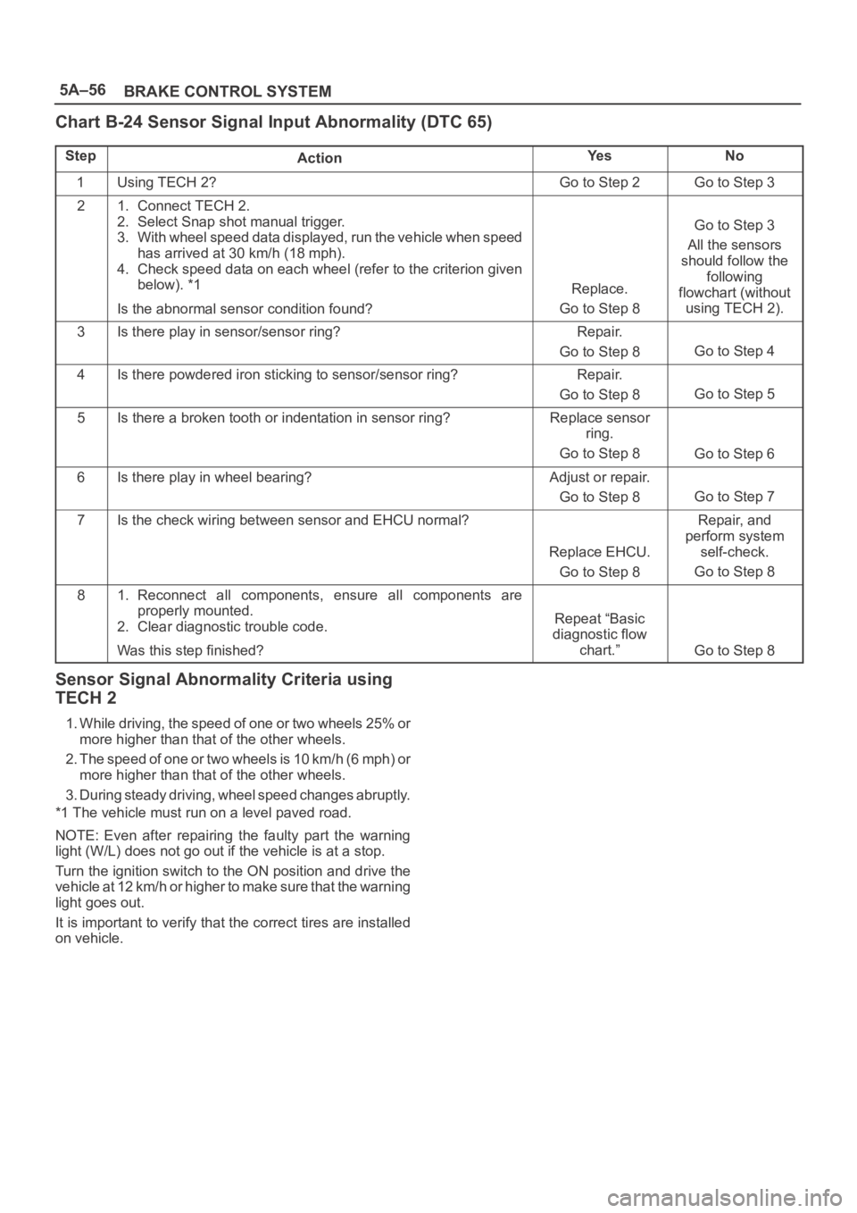
5A–56
BRAKE CONTROL SYSTEM
Chart B-24 Sensor Signal Input Abnormality (DTC 65)
StepActionYe sNo
1Using TECH 2?Go to Step 2Go to Step 3
21. Connect TECH 2.
2. Select Snap shot manual trigger.
3. With wheel speed data displayed, run the vehicle when speed
has arrived at 30 km/h (18 mph).
4. Check speed data on each wheel (refer to the criterion given
below). *1
Is the abnormal sensor condition found?
Replace.
Go to Step 8
Go to Step 3
All the sensors
should follow the
following
flowchart (without
using TECH 2).
3Is there play in sensor/sensor ring?Repair.
Go to Step 8
Go to Step 4
4Is there powdered iron sticking to sensor/sensor ring?Repair.
Go to Step 8
Go to Step 5
5Is there a broken tooth or indentation in sensor ring?Replace sensor
ring.
Go to Step 8
Go to Step 6
6Is there play in wheel bearing?Adjust or repair.
Go to Step 8
Go to Step 7
7Is the check wiring between sensor and EHCU normal?
Replace EHCU.
Go to Step 8
Repair, and
perform system
self-check.
Go to Step 8
81. Reconnect all components, ensure all components are
properly mounted.
2. Clear diagnostic trouble code.
Was this step finished?
Repeat “Basic
diagnostic flow
chart.”
Go to Step 8
Sensor Signal Abnormality Criteria using
TECH 2
1. While driving, the speed of one or two wheels 25% or
more higher than that of the other wheels.
2. The speed of one or two wheels is 10 km/h (6 mph) or
more higher than that of the other wheels.
3. During steady driving, wheel speed changes abruptly.
*1 The vehicle must run on a level paved road.
NOTE: Even after repairing the faulty part the warning
light (W/L) does not go out if the vehicle is at a stop.
Turn the ignition switch to the ON position and drive the
vehicle at 12 km/h or higher to make sure that the warning
light goes out.
It is important to verify that the correct tires are installed
on vehicle.
Page 957 of 6000
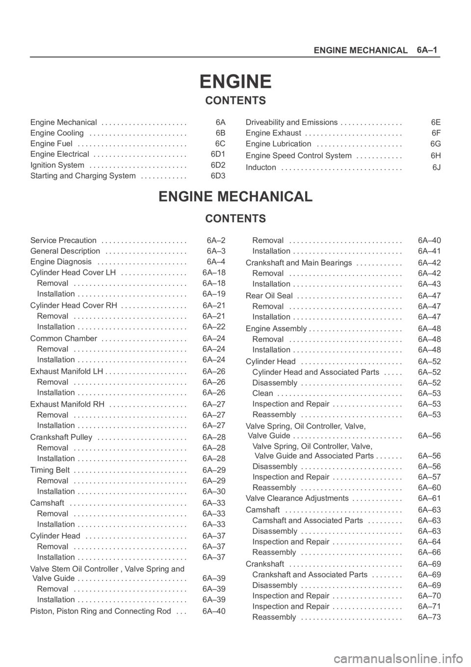
6A–1
ENGINE MECHANICAL
ENGINE
CONTENTS
Engine Mechanical 6A. . . . . . . . . . . . . . . . . . . . . .
Engine Cooling 6B. . . . . . . . . . . . . . . . . . . . . . . . .
Engine Fuel 6C. . . . . . . . . . . . . . . . . . . . . . . . . . . .
Engine Electrical 6D1. . . . . . . . . . . . . . . . . . . . . . . .
Ignition System 6D2. . . . . . . . . . . . . . . . . . . . . . . . .
Starting and Charging System 6D3. . . . . . . . . . . . Driveability and Emissions 6E. . . . . . . . . . . . . . . .
Engine Exhaust 6F. . . . . . . . . . . . . . . . . . . . . . . . .
Engine Lubrication 6G. . . . . . . . . . . . . . . . . . . . . .
Engine Speed Control System 6H. . . . . . . . . . . .
Inducton 6J. . . . . . . . . . . . . . . . . . . . . . . . . . . . . . .
ENGINE MECHANICAL
CONTENTS
Service Precaution 6A–2. . . . . . . . . . . . . . . . . . . . . .
General Description 6A–3. . . . . . . . . . . . . . . . . . . . .
Engine Diagnosis 6A–4. . . . . . . . . . . . . . . . . . . . . . .
Cylinder Head Cover LH 6A–18. . . . . . . . . . . . . . . . .
Removal 6A–18. . . . . . . . . . . . . . . . . . . . . . . . . . . . .
Installation 6A–19. . . . . . . . . . . . . . . . . . . . . . . . . . . .
Cylinder Head Cover RH 6A–21. . . . . . . . . . . . . . . . .
Removal 6A–21. . . . . . . . . . . . . . . . . . . . . . . . . . . . .
Installation 6A–22. . . . . . . . . . . . . . . . . . . . . . . . . . . .
Common Chamber 6A–24. . . . . . . . . . . . . . . . . . . . . .
Removal 6A–24. . . . . . . . . . . . . . . . . . . . . . . . . . . . .
Installation 6A–24. . . . . . . . . . . . . . . . . . . . . . . . . . . .
Exhaust Manifold LH 6A–26. . . . . . . . . . . . . . . . . . . . .
Removal 6A–26. . . . . . . . . . . . . . . . . . . . . . . . . . . . .
Installation 6A–26. . . . . . . . . . . . . . . . . . . . . . . . . . . .
Exhaust Manifold RH 6A–27. . . . . . . . . . . . . . . . . . . .
Removal 6A–27. . . . . . . . . . . . . . . . . . . . . . . . . . . . .
Installation 6A–27. . . . . . . . . . . . . . . . . . . . . . . . . . . .
Crankshaft Pulley 6A–28. . . . . . . . . . . . . . . . . . . . . . .
Removal 6A–28. . . . . . . . . . . . . . . . . . . . . . . . . . . . .
Installation 6A–28. . . . . . . . . . . . . . . . . . . . . . . . . . . .
Timing Belt 6A–29. . . . . . . . . . . . . . . . . . . . . . . . . . . . .
Removal 6A–29. . . . . . . . . . . . . . . . . . . . . . . . . . . . .
Installation 6A–30. . . . . . . . . . . . . . . . . . . . . . . . . . . .
Camshaft 6A–33. . . . . . . . . . . . . . . . . . . . . . . . . . . . . .
Removal 6A–33. . . . . . . . . . . . . . . . . . . . . . . . . . . . .
Installation 6A–33. . . . . . . . . . . . . . . . . . . . . . . . . . . .
Cylinder Head 6A–37. . . . . . . . . . . . . . . . . . . . . . . . . .
Removal 6A–37. . . . . . . . . . . . . . . . . . . . . . . . . . . . .
Installation 6A–37. . . . . . . . . . . . . . . . . . . . . . . . . . . .
Valve Stem Oil Controller , Valve Spring and
Valve Guide 6A–39. . . . . . . . . . . . . . . . . . . . . . . . . . . .
Removal 6A–39. . . . . . . . . . . . . . . . . . . . . . . . . . . . .
Installation 6A–39. . . . . . . . . . . . . . . . . . . . . . . . . . . .
Piston, Piston Ring and Connecting Rod 6A–40. . . Removal 6A–40. . . . . . . . . . . . . . . . . . . . . . . . . . . . .
Installation 6A–41. . . . . . . . . . . . . . . . . . . . . . . . . . . .
Crankshaft and Main Bearings 6A–42. . . . . . . . . . . .
Removal 6A–42. . . . . . . . . . . . . . . . . . . . . . . . . . . . .
Installation 6A–43. . . . . . . . . . . . . . . . . . . . . . . . . . . .
Rear Oil Seal 6A–47. . . . . . . . . . . . . . . . . . . . . . . . . . .
Removal 6A–47. . . . . . . . . . . . . . . . . . . . . . . . . . . . .
Installation 6A–47. . . . . . . . . . . . . . . . . . . . . . . . . . . .
Engine Assembly 6A–48. . . . . . . . . . . . . . . . . . . . . . . .
Removal 6A–48. . . . . . . . . . . . . . . . . . . . . . . . . . . . .
Installation 6A–48. . . . . . . . . . . . . . . . . . . . . . . . . . . .
Cylinder Head 6A–52. . . . . . . . . . . . . . . . . . . . . . . . . .
Cylinder Head and Associated Parts 6A–52. . . . .
Disassembly 6A–52. . . . . . . . . . . . . . . . . . . . . . . . . .
Clean 6A–53. . . . . . . . . . . . . . . . . . . . . . . . . . . . . . . .
Inspection and Repair 6A–53
. . . . . . . . . . . . . . . . . .
Reassembly 6A–53. . . . . . . . . . . . . . . . . . . . . . . . . .
Valve Spring, Oil Controller, Valve,
Valve Guide 6A–56. . . . . . . . . . . . . . . . . . . . . . . . . . . .
Valve Spring, Oil Controller, Valve,
Valve Guide and Associated Parts 6A–56. . . . . . .
Disassembly 6A–56. . . . . . . . . . . . . . . . . . . . . . . . . .
Inspection and Repair 6A–57. . . . . . . . . . . . . . . . . .
Reassembly 6A–60. . . . . . . . . . . . . . . . . . . . . . . . . .
Valve Clearance Adjustments 6A–61. . . . . . . . . . . . .
Camshaft 6A–63. . . . . . . . . . . . . . . . . . . . . . . . . . . . . .
Camshaft and Associated Parts 6A–63. . . . . . . . .
Disassembly 6A–63. . . . . . . . . . . . . . . . . . . . . . . . . .
Inspection and Repair 6A–64. . . . . . . . . . . . . . . . . .
Reassembly 6A–66. . . . . . . . . . . . . . . . . . . . . . . . . .
Crankshaft 6A–69. . . . . . . . . . . . . . . . . . . . . . . . . . . . .
Crankshaft and Associated Parts 6A–69. . . . . . . .
Disassembly 6A–69. . . . . . . . . . . . . . . . . . . . . . . . . .
Inspection and Repair 6A–70. . . . . . . . . . . . . . . . . .
Inspection and Repair 6A–71. . . . . . . . . . . . . . . . . .
Reassembly 6A–73. . . . . . . . . . . . . . . . . . . . . . . . . .