engine OPEL FRONTERA 1998 Workshop Manual
[x] Cancel search | Manufacturer: OPEL, Model Year: 1998, Model line: FRONTERA, Model: OPEL FRONTERA 1998Pages: 6000, PDF Size: 97 MB
Page 5723 of 6000
7A–34
AUTOMATIC TRANSMISSION (4L30–E)
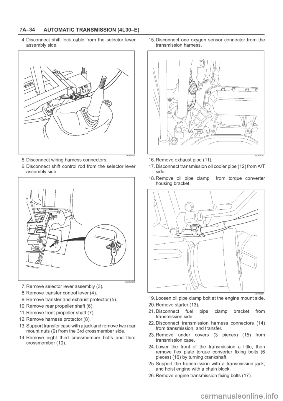
4. Disconnect shift lock cable from the selector lever
assembly side.
256RW012
5. Disconnect wiring harness connectors.
6. Disconnect shift control rod from the selector lever
assembly side.
256RW013
7. Remove selector lever assembly (3).
8. Remove transfer control lever (4).
9. Remove transfer and exhaust protector (5).
10. Remove rear propeller shaft (6).
11. Remove front propeller shaft (7).
12. Remove harness protector (8).
13. Support transfer case with a jack and remove two rear
mount nuts (9) from the 3rd crossmember side.
14. Remove eight third crossmember bolts and third
crossmember (10).15. Disconnect one oxygen sensor connector from the
transmission harness.
150RW002
16. Remove exhaust pipe (11).
17. Disconnect transmission oil cooler pipe (12) from A/T
side.
18. Remove oil pipe clamp from torque converter
housing bracket.
253RY001
19. Loosen oil pipe clamp bolt at the engine mount side.
20. Remove starter (13).
21. Disconnect fuel pipe clamp bracket from
transmission side.
22. Disconnect transmission harness connectors (14)
from transmission, and transfer.
23. Remove under covers (3 pieces) (15) from
transmission case.
24. Lower the front of the transmission a little, then
remove flex plate torque converter fixing bolts (6
pieces) (16) by turning crankshaft.
25. Support the transmission with a transmission jack,
and hoist engine with a chain block.
26. Remove engine transmission fixing bolts (17).
Page 5724 of 6000
7A–35 AUTOMATIC TRANSMISSION (4L30–E)
27. Remove transmission assembly (18).
Installation
1. Slowly raise transmission jack until front of the
transmission is aligned with rear of the engine, then
install transmission assembly.
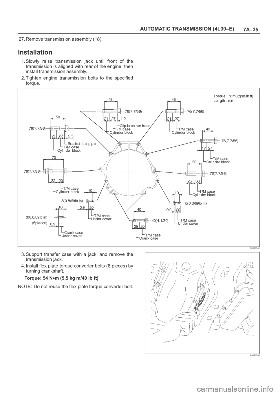
2. Tighten engine transmission bolts to the specified
torque.
F07RW041
3. Support transfer case with a jack, and remove the
transmission jack.
4. Install flex plate torque converter bolts (6 pieces) by
turning crankshaft.
Torque: 54 N
m (5.5 kgꞏm/40 lb ft)
NOTE: Do not reuse the flex plate torque converter bolt.
240RW005
Page 5726 of 6000
7A–37 AUTOMATIC TRANSMISSION (4L30–E)
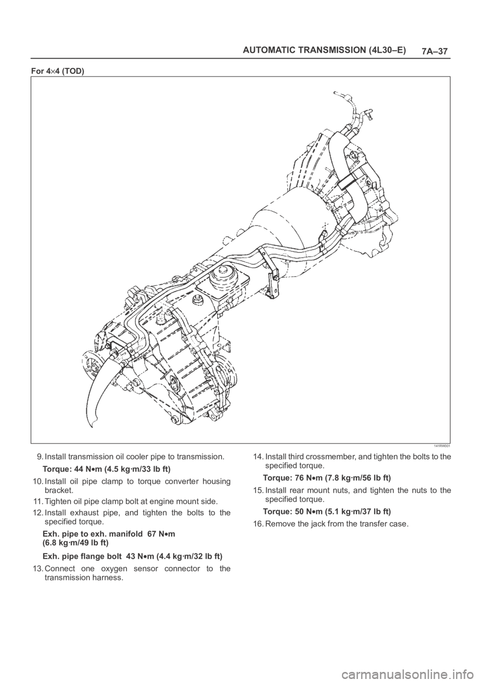
For 44 (TOD)
141RW001
9. Install transmission oil cooler pipe to transmission.
Torque: 44 N
m (4.5 kgꞏm/33 lb ft)
10. Install oil pipe clamp to torque converter housing
bracket.
11. Tighten oil pipe clamp bolt at engine mount side.
12. Install exhaust pipe, and tighten the bolts to the
specified torque.
Exh. pipe to exh. manifold 67 N
m
(6.8 kgꞏm/49 lb ft)
Exh. pipe flange bolt 43 N
m (4.4 kgꞏm/32 lb ft)
13. Connect one oxygen sensor connector to the
transmission harness.14. Install third crossmember, and tighten the bolts to the
specified torque.
To r q u e : 7 6 N
m (7.8 kgꞏm/56 lb ft)
15. Install rear mount nuts, and tighten the nuts to the
specified torque.
To r q u e : 5 0 N
m (5.1 kgꞏm/37 lb ft)
16. Remove the jack from the transfer case.
Page 5727 of 6000
7A–38
AUTOMATIC TRANSMISSION (4L30–E)
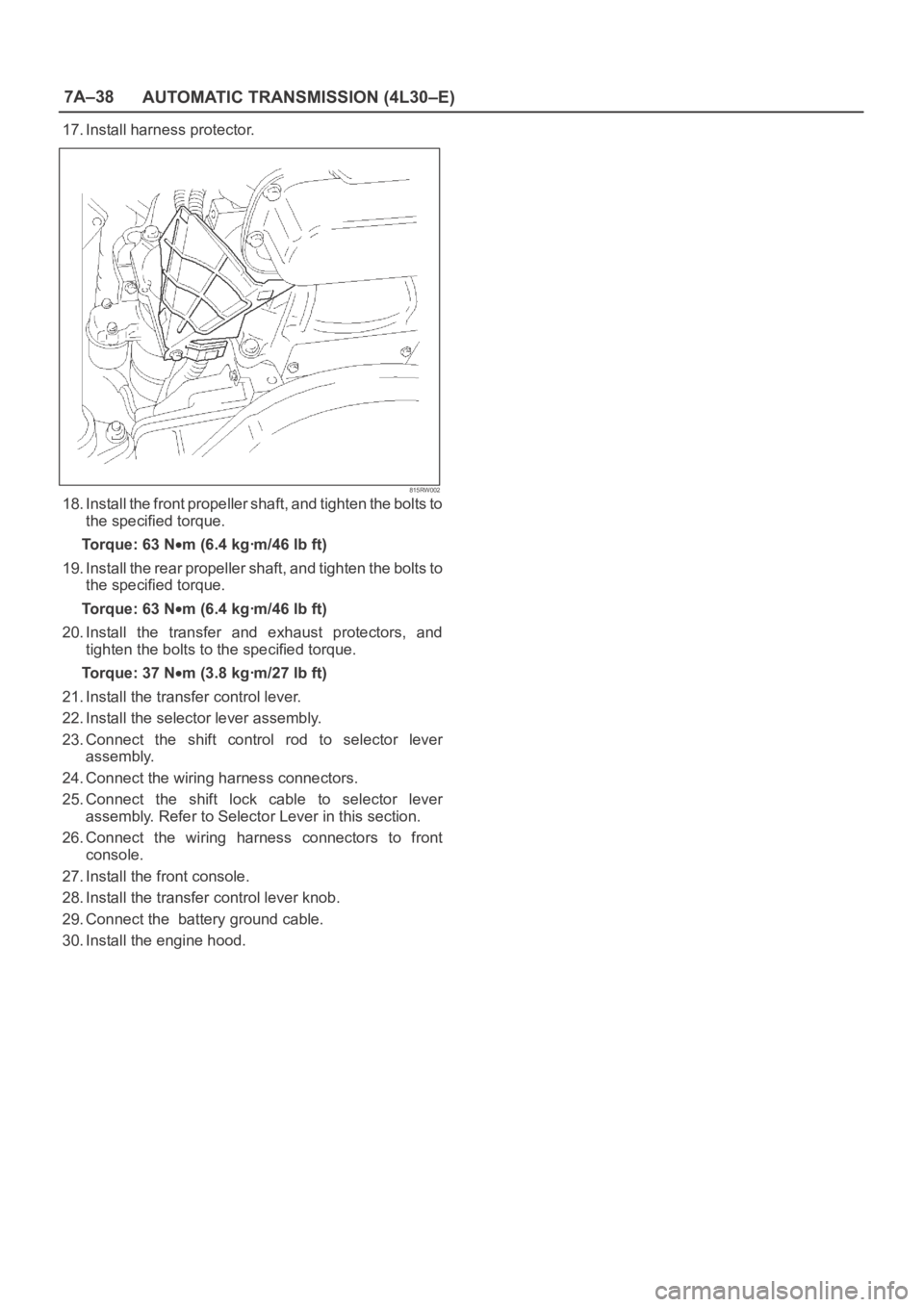
17. Install harness protector.
815RW002
18. Install the front propeller shaft, and tighten the bolts to
the specified torque.
Torque: 63 N
m (6.4 kgꞏm/46 lb ft)
19. Install the rear propeller shaft, and tighten the bolts to
the specified torque.
Torque: 63 N
m (6.4 kgꞏm/46 lb ft)
20. Install the transfer and exhaust protectors, and
tighten the bolts to the specified torque.
Torque: 37 N
m (3.8 kgꞏm/27 lb ft)
21. Install the transfer control lever.
22. Install the selector lever assembly.
23. Connect the shift control rod to selector lever
assembly.
24. Connect the wiring harness connectors.
25. Connect the shift lock cable to selector lever
assembly. Refer to Selector Lever in this section.
26. Connect the wiring harness connectors to front
console.
27. Install the front console.
28. Install the transfer control lever knob.
29. Connect the battery ground cable.
30. Install the engine hood.
Page 5748 of 6000
7A–59 AUTOMATIC TRANSMISSION (4L30–E)
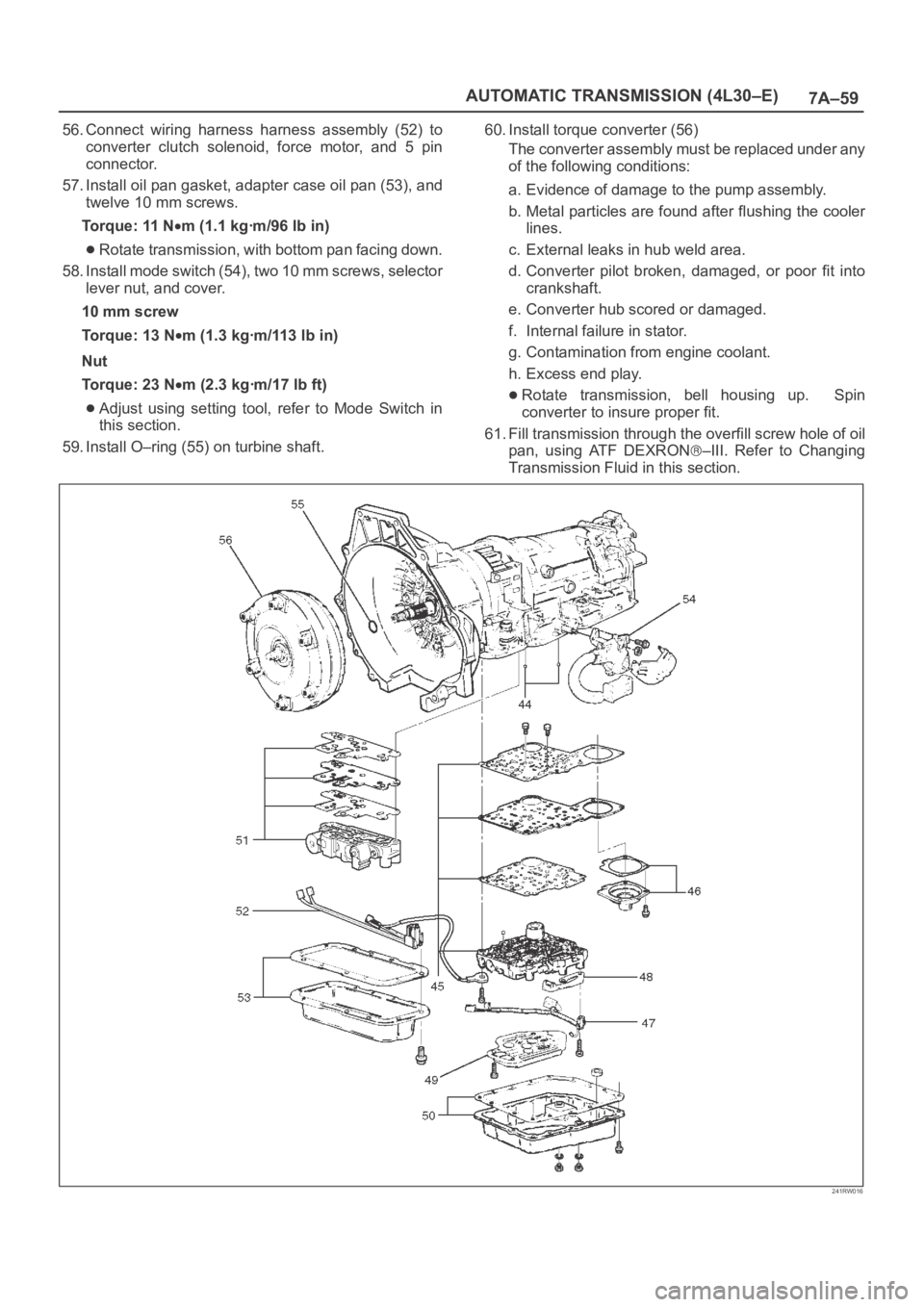
56. Connect wiring harness harness assembly (52) to
converter clutch solenoid, force motor, and 5 pin
connector.
57. Install oil pan gasket, adapter case oil pan (53), and
twelve 10 mm screws.
Torque: 11 N
m (1.1 kgꞏm/96 lb in)
Rotate transmission, with bottom pan facing down.
58. Install mode switch (54), two 10 mm screws, selector
lever nut, and cover.
10 mm screw
Torque: 13 N
m (1.3 kgꞏm/113 lb in)
Nut
Torque: 23 N
m (2.3 kgꞏm/17 lb ft)
Adjust using setting tool, refer to Mode Switch in
this section.
59. Install O–ring (55) on turbine shaft.60. Install torque converter (56)
The converter assembly must be replaced under any
of the following conditions:
a. Evidence of damage to the pump assembly.
b. Metal particles are found after flushing the cooler
lines.
c. External leaks in hub weld area.
d. Converter pilot broken, damaged, or poor fit into
crankshaft.
e. Converter hub scored or damaged.
f. Internal failure in stator.
g. Contamination from engine coolant.
h. Excess end play.Rotate transmission, bell housing up. Spin
converter to insure proper fit.
61. Fill transmission through the overfill screw hole of oil
pan, using ATF DEXRON
–III. Refer to Changing
Transmission Fluid in this section.
241RW016
Page 5768 of 6000
7A–79 AUTOMATIC TRANSMISSION (4L30–E)
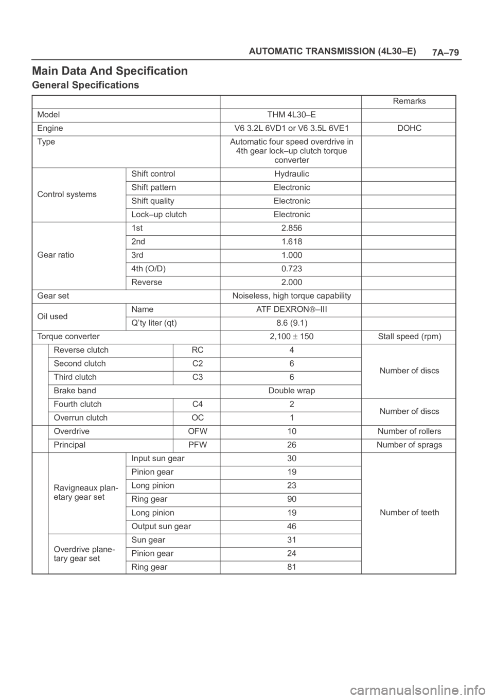
Main Data And Specification
General Specifications
Remarks
ModelTHM 4L30–E
EngineV6 3.2L 6VD1 or V6 3.5L 6VE1DOHC
Ty p eAutomatic four speed overdrive in
4th gear lock–up clutch torque
converter
Shift controlHydraulic
Control systemsShift patternElectronicControl systemsShift qualityElectronic
Lock–up clutchElectronic
1st2.856
2nd1.618
Gear ratio3rd1.000
4th (O/D)0.723
Reverse2.000
Gear setNoiseless, high torque capability
Oil usedNameAT F D E X R O N–IIIOil usedQ’ty liter (qt)8.6 (9.1)
Torque converter2,100 150Stall speed (rpm)
Reverse clutchRC4
Second clutchC26Number of discsThird clutchC36Number of discs
Brake bandDouble wrap
Fourth clutchC42Number of discsOverrun clutchOC1Number of discs
OverdriveOFW10Number of rollers
PrincipalPFW26Number of sprags
Input sun gear30
Pinion gear19
Ravigneaux plan-Long pinion23g
etary gear setRing gear90
Long pinion19Number of teeth
Output sun gear46
Odi l
Sun gear31
Overdrive plane-
tary gear setPinion gear24tary gear set
Ring gear81
Page 5788 of 6000

AUTOMATIC TRANSMISSION (AW30-40LE) 7A–7
CONTROL AND FUNCTIONS
Item Description
Shift and lock-up control • In D range, speed change point and Lock-up point can be changed by
setting pattern selection switch to "POWER", "NORMAL" or "WINTER"
mode.
• Gear shift position in the conditions made up of transmission shift positions
(D.2.L) combined with pattern selection switch (POWER, NORMAL, and
WINTER) can be controlled in accordance with vehicle speed and the
opening of throttle valve.
Overdrive cut control • If O/D OFF switch is set on in D range (O/D OFF lamp ON), gear shift to O/
D is not effected.
• Overdrive is released at O/D OFF switch on and high transmission oil
temperature (More than 130
C).
However, to prevent engine over revolution
•4
3 shifting at vehicle speed is less than 118 km/h.
•3
4 shifting at vehicle speed is more than 131 km/h.
Lock-up cut control • In D range, 3rd or O/D lock-up is conducted in "POWER" or "NORMAL"
mode.
• In 2, L range, lock-up is off in the whole area.
• Lock-up timing is controlled to reduce gear shift shock using kind of gear
shift (shift up, etc.) lock-up status at the time of gear shift judgement, gear
step and throttle opening after gear shift.
• Lock-up is released at brake on or high transmission oil temperature (More
than 130
C).
• Lock-up is prohibited when idling is defected by throttle position sensor.
Driving mode select control • The TCM selects a suitable driving mode from the nine kinds for the variety
driving condition.
i) Economy mode ii) Power mode iii) Winter mode iv) HOT1 mode v) HOT2
mode vi) L4 mode vii) Slope mode (Up slope 1, Up slope 2 and Down
slope mode)
• The priority of driving mode:
Economy < Power < Slope < L4 < Winter < HOT1 < HOT2
Squat control • When the TCM detects D signal on, the TCM controls 1–3–1 shift by
setting a timer, in order to improve the shift feel at N
D.
Line pressure control • The TCM output current which corresponds to throttle oil pressure to
pressure control solenoid based on throttle opening.
Indicate oil temperature warning
function• If the transmission oil temperature sensor senses that transmission oil
temperature is greater than 146
C, the TCM turn on A/T OIL TEMP
warning lamp. (The warning lamp is turned off, if oil temperature is less
than 126
C.)
L4 mode control • The TCM judges whether the transfer is engaged in high or low based on
the ratio rpm data from output speed sensor in the transmission and the
rpm data from speed meter sensor to select the shift map.
Up and down hill control • The TCM judges up and down hill, and change shift pattern based on
throttle opening and acceleration.
Correct oil temperature control • If the temperature exceeds a predetermined value, the TCM selects the
high oil temperature shift point for downshifting, thus preventing the oil
temperature from rising. (More than 130
C, D range)
Page 5790 of 6000

AUTOMATIC TRANSMISSION (AW30-40LE) 7A–9
MAJOR INPUT/OUTPUT COMPONENTS
Component Function
Input
Vehicle speed sensor (Speedometer) Detects the vehicle speed (Back-up sensor of output
revolution sensor).
Output revolution sensor (Transmission) Detects the vehicle speed.
Input revolution sensor (Transmission) Detects the input revolution (O/D direct clutch drum
revolution).
Engine revolution sensor Detects the engine revolution.
Throttle position sensor Detects the throttle opening rate.
Neutral start switch Detects the select lever position.
Pattern select switch Detects whether the driver has selected "NORMAL",
"POWER", or "WINTER" mode.
Overdrive off switch Detects whether the driver has selected O/D.
Brake lamp switch Detects whether the driver has pressed the brake pedal or
not.
Oil temperature sensor Detects the oil temperature.
Diagnostic star t switch Star ts self-diagnosis and displays a code for faulty part if
any.
Input/Output
Data link connector When connected with Tech2 or tester, can communicate
the data for function check, etc.
Output
Shift solenoid S1, S2 Selects shift point and gear position suited to the vehicle
running condition on the basis of TCM output.
Lock-up control solenoid SL Control the lock-up clutch suited to the vehicle running
condition on the basis of TCM output.
Pressure control solenoid STH Adjusts throttle pressure by energizing current of linear
pressure control solenoid to prevent the shift shock and to
obtain shift smoothly.
"CHECK TRANS" lamp When trouble has occurred to throttle position sensor,
vehicle speed sensor, or solenoid, "CHECK TRANS" lamp
is blinked to warn the driver. If also displays the trouble
code.
A/T OIL TEMP warning lamp Lights when ATF oil temperature rises. (Turned on at
greater than 146
C . Turned off at less than 126C.
Power mode lamp Informs the driver whether the vehicle is in power mode or
not.
Winter mode lamp Informs the driver whether the vehicle is in winter mode or
not.
Computer
Transmission Control Module (TCM) Based on the signal from each switch and sensors, judges
necessary shift point and lock-up operation, and send
signal to each solenoid.
Page 5795 of 6000
7A–14 AUTOMATIC TRANSMISSION (AW30-40LE)
821RY00012
F07LV002
740RY00013
740RY00014
SELF-DIAGNOSIS
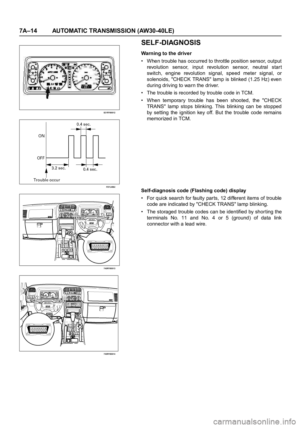
Warning to the driver
• When trouble has occurred to throttle position sensor, output
revolution sensor, input revolution sensor, neutral star t
switch, engine revolution signal, speed meter signal, or
solenoids, "CHECK TRANS" lamp is blinked (1.25 Hz) even
during driving to warn the driver.
• The trouble is recorded by trouble code in TCM.
• When temporary trouble has been shooted, the "CHECK
TRANS" lamp stops blinking. This blinking can be stopped
by setting the ignition key off. But the trouble code remains
memorized in TCM.
Self-diagnosis code (Flashing code) display
• For quick search for faulty parts, 12 different items of trouble
code are indicated by "CHECK TRANS" lamp blinking.
• The storaged trouble codes can be identified by shor ting the
terminals No. 11 and No. 4 or 5 (ground) of data link
connector with a lead wire.
Page 5801 of 6000

7A–20 AUTOMATIC TRANSMISSION (AW30-40LE)
Once the test vehicle has been identified an “Application
(Power train) Menu" screen appears. Please select the
appropriate application.
The following table shows, which functions are used for
the available equipment versions.
Diagnostic Trouble Codes
The purpose of the “Diagnostic Trouble Codes" mode is
to display stored TCM trouble codes.
When “Diagnostic Trouble Codes" is selected an
“Application Menu" screen appears.
Clear DTC Information
The purpose of the “Clear DTC Information" mode is to
command the clearing of stored TCM trouble codes.
When “Clear DTC Information" is selected, a “Clear
DTC Information", warning screen appears. This screen
informs you that by cleaning DTC's, “all stored DTC
information in controller will be erased".
Do you want to clear DTC's (Yes/No).
Press either the Yes or No key when answering.
After clearing codes, confirm system operation by test
driving the vehicle.
Allow the vehicle to shift through all four forward gears in
a manner which attempts to repeat the failure condition.
NOTE: When the trouble has not been repaired and thetrouble code cannot be erased, check the vehicle again.
DTC Information
When “DTC Information" is selected, an “Application
Menu" appears with a list of DTC information function
keys addressing DTC specifics and their origins.
Function key selections may vary for particular vehicle
and/or system.
Data Display
The purpose of the “Data Display" mode is to
continuously monitor data parameters.
The current actual values of all impor tant sensors and
signals in the system are display through F1 mode.
When “Data Display" is selected an “Application Menu"
appears.
See “TRANSMISSION DATA" and “TCC DATA” on next
page.
Snapshot
When “Snapshot" is selected an “Application Menu"
appears.
When “Transmission Snapshot" application is selected
from the “Application Menu", a “Snapshot Menu"
appears, displaying several options. “Snapshot" options
may vary from one system to another.
“Snapshot" allows a recording of all vehicle parameters.
There parameters may then be replayed at a future
point in time.
This action allows you to focus on making the condition
occur, rather than trying to view all of the data in
anticipation of the fault. The snapshot will collect
parameter information around a trigger point that you
select.
When a snapshot is taken. It is recorded onto the
PCMCIA memory card. When the Tech2 is powered
down. Snapshots are not lost.
Actuator Tests
The purpose of “Actuator Tests" mode is to check for
correct operation of electronic system actuators.
Lamps
You can operate the lamps by pressing the ON and OFF
buttons.
Preconditions: P or N position
Solenoid
Solenoid S1(1-2/3-4), S2(2-3) and TCC Solenoid
(Torque Converter Clutch)
You can operate the solenoids by pressing the ON and
OFF buttons.
Preconditions: P or N position, no vehicle speed, no
engine speed
Pressure Control Solenoid (PCS)
You can operate the PC Solenoid by pressing the ON
and OFF buttons. ON will command a maximum current
of 1000 mA and OFF a minimum of 200 mA.
Preconditions: P or N position, no vehicle speed, engine
running F0: Diagnostic Trouble Codes
F0: Read DTC Info Ordered By Priority
F1: Clear DTC Information
F2: DTC Information
F0: History
F1: MIL SVS or Message Requested
F2: Last Test Failed
F3: Test Failed Since Code Cleared
F4: Not Ran Since Code Cleared
F5: Failed This Ignition
F1: Data Display
F0: Transmission Data
F1: TCC Data
F2: Snapshot
F3: Actuator Tests
F0: Lamps
F0: Check Light Test
F1: Power Lamp Test
F2: Winter Lamp Test
F3: AT Oil Temperature Lamp Test
F1: Solenoids
F0: Solenoid 2-3 Test
F1: Solenoid 1-2/3-4 Test
F2: TCC Solenoid Test
F3: Pressure Control Solenoid (PCS)