ignition OPEL FRONTERA 1998 Workshop Manual
[x] Cancel search | Manufacturer: OPEL, Model Year: 1998, Model line: FRONTERA, Model: OPEL FRONTERA 1998Pages: 6000, PDF Size: 97 MB
Page 1935 of 6000

6E–42
4JX1–TC ENGINE DRIVEABILITY AND EMISSIONS
4JX1-TC Engine (Automatic and Manual Transmission)
Te c h 2
Parameter
Data ListUnits
DisplayedTy p i c a l D a t a
Values (IDLE)Typical Data
Va l u e s
(2500 RPM)Refer To
Battery VoltageEngineVo l t s12.5 14.513 15General Description
Ignition StatusEngineOn/OffOnOnGeneral Description
Ignition Relay2EngineOn/OffOnOnGeneral Description
Idle SwitchEngineInactive/
Active——DTC P0510, P1510
Manifold
Absolute
PressureEngineKPa96 106110 150General Description
DTC P0107, P0108
Rail Oil
PressureEngineMPa3.5 54.5 10General Description
DTC P0192, P0193
Desired Rail Oil
PressureEngineMPa4 55 9General Description
DTC P0192, P0193
Fuel
TemperatureEngineC (F)75 8575 85DTC P0182, P0183
Quick Warming
SwitchEngineOn/OffOffOffDTC P0380
Thermo RelayEngineOn/Off——DTC P1655
Actual EGR
PressureEngineKPa58 60M/T 63 66
A/T 95
105
DTC P0405, P0406
Barometric
PressureEngineKPa98 10298 102General Description
Relative EGR
PressureEngineKPa–38 –45M/T –34 –37
A/T 0General Description
Desired EGR
PressureEngineKPa–43 –40M/T 36
A/T 0General Description
Brake SwitchEngineInactive/
Active——DTC P1588
GearEngine————
Vehicle SpeedEngineKm/h00Transmission Diagnosis
Rail Pressure
Control ValveEngine%17 2218 27DTC P1193
EGR StatusEngineDisable/
EnableEnableM/T Enable
A/T DisableGeneral Description
EGR Switching
Va l v eEngineOn/Off——General Description
Throttle Motor
Position SensorEngineVo l t s3.1 3.90.2 0.9DTC P1485, P1486,
P1487
Throttle Motor
PositionEngineSteps
0 1.00 1.0
DTC P1488
Delirered Fuel
QuantityEnginemm 3/st
6 106 12
General Description
Injector StatusEngineDisable/
EnableEnableEnableDTC P0201, P0202,
P0203, P0204, General
Description
Injector Pulse
WidthEnginems0.9 1.250.7 1.1General Description
Injector Start
OffsetEngineCA——General Description
Page 1937 of 6000

6E–44
4JX1–TC ENGINE DRIVEABILITY AND EMISSIONS
No Malfunction Indicator Lamp (MIL)
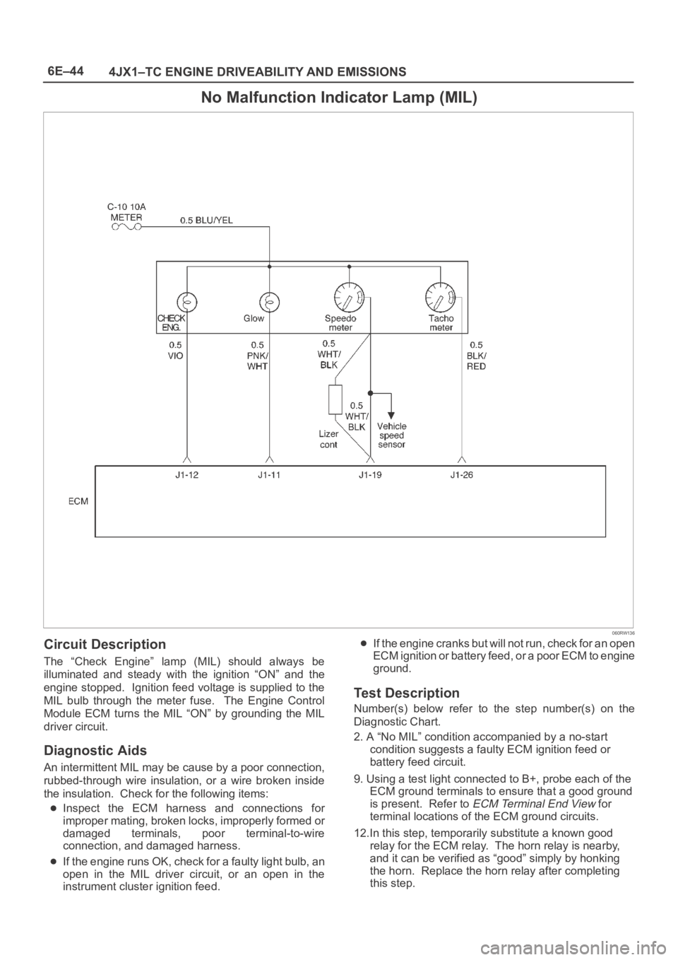
060RW136
Circuit Description
The “Check Engine” lamp (MIL) should always be
illuminated and steady with the ignition “ON” and the
engine stopped. Ignition feed voltage is supplied to the
MIL bulb through the meter fuse. The Engine Control
Module ECM turns the MIL “ON” by grounding the MIL
driver circuit.
Diagnostic Aids
An intermittent MIL may be cause by a poor connection,
rubbed-through wire insulation, or a wire broken inside
the insulation. Check for the following items:
Inspect the ECM harness and connections for
improper mating, broken locks, improperly formed or
damaged terminals, poor terminal-to-wire
connection, and damaged harness.
If the engine runs OK, check for a faulty light bulb, an
open in the MIL driver circuit, or an open in the
instrument cluster ignition feed.
If the engine cranks but will not run, check for an open
ECM ignition or battery feed, or a poor ECM to engine
ground.
Test Description
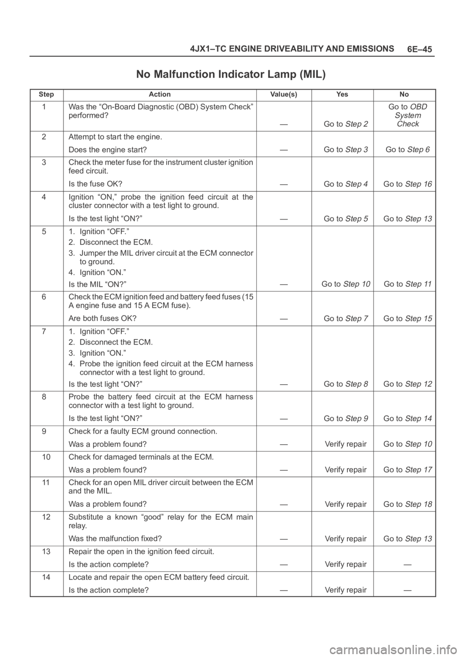
Number(s) below refer to the step number(s) on the
Diagnostic Chart.
2. A “No MIL” condition accompanied by a no-start
condition suggests a faulty ECM ignition feed or
battery feed circuit.
9. Using a test light connected to B+, probe each of the
ECM ground terminals to ensure that a good ground
is present. Refer to
ECM Terminal End View for
terminal locations of the ECM ground circuits.
12.In this step, temporarily substitute a known good
relay for the ECM relay. The horn relay is nearby,
and it can be verified as “good” simply by honking
the horn. Replace the horn relay after completing
this step.
Page 1938 of 6000

6E–45 4JX1–TC ENGINE DRIVEABILITY AND EMISSIONS
No Malfunction Indicator Lamp (MIL)
StepActionVa l u e ( s )Ye sNo
1Was the “On-Board Diagnostic (OBD) System Check”
performed?
—Go to Step 2
Go to OBD
System
Check
2Attempt to start the engine.
Does the engine start?
—Go to Step 3Go to Step 6
3Check the meter fuse for the instrument cluster ignition
feed circuit.
Is the fuse OK?
—Go to Step 4Go to Step 16
4Ignition “ON,” probe the ignition feed circuit at the
cluster connector with a test light to ground.
Is the test light “ON?”
—Go to Step 5Go to Step 13
51. Ignition “OFF.”
2. Disconnect the ECM.
3. Jumper the MIL driver circuit at the ECM connector
to ground.
4. Ignition “ON.”
Is the MIL “ON?”
—Go to Step 10Go to Step 11
6Check the ECM ignition feed and battery feed fuses (15
A engine fuse and 15 A ECM fuse).
Are both fuses OK?
—Go to Step 7Go to Step 15
71. Ignition “OFF.”
2. Disconnect the ECM.
3. Ignition “ON.”
4. Probe the ignition feed circuit at the ECM harness
connector with a test light to ground.
Is the test light “ON?”
—Go to Step 8Go to Step 12
8Probe the battery feed circuit at the ECM harness
connector with a test light to ground.
Is the test light “ON?”
—Go to Step 9Go to Step 14
9Check for a faulty ECM ground connection.
Was a problem found?
—Verify repairGo to Step 10
10Check for damaged terminals at the ECM.
Was a problem found?
—Verify repairGo to Step 17
11Check for an open MIL driver circuit between the ECM
and the MIL.
Was a problem found?
—Verify repairGo to Step 18
12Substitute a known “good” relay for the ECM main
relay.
Was the malfunction fixed?
—Verify repairGo to Step 13
13Repair the open in the ignition feed circuit.
Is the action complete?
—Verify repair—
14Locate and repair the open ECM battery feed circuit.
Is the action complete?
—Verify repair—
Page 1939 of 6000

6E–46
4JX1–TC ENGINE DRIVEABILITY AND EMISSIONS
No Malfunction Indicator Lamp (MIL)
StepNo Ye s Va l u e ( s ) Action
15Locate and repair the short to ground in the ECM
ignition feed circuit or ECM battery feed circuit.
Is the action complete?
—Verify repair—
16Locate and repair the short to ground in the ignition
feed circuit to the instrument cluster, and replace the
fuse.
Is the action complete?
—Verify repair—
17Replace the ECM (Refer to the Data Programming in
Case of ECM change).
Is the action complete?
—Verify repair—
18Check the MIL driver circuit for a poor connection at the
instrument panel connector.
Was a problem found?
—Verify repair
Go to
Instrument
Panel
in
Electrical
Diagnosis
Page 1940 of 6000

6E–47 4JX1–TC ENGINE DRIVEABILITY AND EMISSIONS
Malfunction Indicator Lamp (MIL) “ON” Steady
060RW136
Circuit description
The “Check Engine” lamp (MIL) should always be
illuminated and steady with ignition “ON” and the engine
stopped. Ignition feed voltage is supplied directly to the
MIL indicator. The Engine Control Module ECM turns the
MIL “ON” by grounding the MIL driver circuit.
The MIL should not remain “ON” with the engine running
and no DTC(s) set. A steady MIL with the engine running
and no DTC(s) suggests a short to ground in the MIL
driver circuit.
Diagnostic Aids
An intermittent may be caused by a poor connection,
rubbed–through wire insulation, or a wire broken inside
the insulation. Check for the following items:
Poor connection or damaged harness – Inspect the
ECM harness and connectors for improper mating,
broken locks, improperly formed or damaged
terminals, poor terminal-to-wire connection, and
damaged harness.
Test Description
Number(s) below refer to the step number(s) on the
Diagnostic Chart.
2. If the MIL does not remain “ON” when the ECM is
disconnected, the MIL driver wiring is not faulty.
3. If the MIL driver circuit is OK, the instrument panel
cluster is faulty.
Page 1941 of 6000

6E–48
4JX1–TC ENGINE DRIVEABILITY AND EMISSIONS
Malfunction Indicator Lamp (MIL) “ON” Steady
StepActionVa l u e ( s )Ye sNo
1Was the “On-Board diagnostic (OBD) System Check”
performed?
—Go to Step 2
Go to OBD
System
Check
21. Ignition “OFF,” disconnect ECM.
2. Ignition “ON,” observe the MIL (CHECK ENGINE
lamp).
Is the MIL “ON?”
—Go to Step 3Go to Step 5
31. Ignition “OFF,” disconnect the instrument panel
cluster.
2. Check the MIL driver circuit between the ECM and
the instrument panel cluster for a short to ground.
3. If a problem is found, repair as necessary.
Was the MIL driver circuit shorted to ground?
—
Go to OBD
System
Check
Go to Step 4
4Replace the instrument panel cluster.
Is the action complete?
—
Go to OBD
System
Check
—
51. Ignition “OFF,” reconnect the ECM.
2. Ignition “ON,” reprogram the ECM. Refer to
On-Vehicle Service in Engine Control Module and
Sensor
for procedures.
3. Using the Tech 2 output controls function, select
MIL dash lamp control and command the MIL
“OFF.”
Did the MIL turn “OFF?”
—
Go to OBD
System
Check
Go to Step 6
6Replace the ECM (Refer to the Data Programming in
Case of ECM change).
Is the action complete?
—
Go to OBD
System
Check
—
Page 1943 of 6000

6E–50
4JX1–TC ENGINE DRIVEABILITY AND EMISSIONS
Engine Cranks But Will Not Run
StepNo Ye s Va l u e ( s ) Action
10Refer to Engine Mechanical Diagnosis to diagnose the
following conditions:
Faulty camshaft drive belts
Leaking or sticky valves or rings
Excessive valve deposits
Weak valve springs
Incorrect valve timing
Leaking head gasket
Is the action complete?
—Verify repairGo to Step 11
11Observe the “Engine Speed” data display on the Tech 2
while cranking the engine.
Is the engine RPM indicated? (If the Tech 2 is normally
powered from the cigarette lighter socket, and if the
Tech 2 display goes blank while cranking the engine, it
will be necessary to power the Tech 2 directly from the
vehicle battery.)
—Go to Step 12Go to Step 17
121. At the ECM (female) side of the connector
mentioned in step, connect a test light between the
ignition + terminal and one of the injector driver
circuits at the same connector.
2. Ignition “ON.”
3. Observe the test light, and repeat the test for each
injector driver circuit by oscilloscope.
Did the test light stay on when checking any of the 4
injector driver circuits?
—Go to Step 13Go to Step 15
131. Ignition “OFF,” disconnect the ECM.
2. Ignition “ON,” observe the test light.
Is the test light “ON?”
—Go to Step 14Go to Step 16
14Locate and repair the short to ground in the injector
driver circuit.
Is the action complete?
—Verify repair—
15Check for an open injector driver circuit.
Was a problem found?
—Verify repairGo to Step 16
16Replace the ECM (Refer to the Data Programming in
Case of ECM change).
Is the action complete?
—Verify repair—
171. Raise the vehicle and disconnect the CKP sensor
harness.
2. Ignition “ON.”
3. With a test light to ground, probe the harness
ignition feed terminal.
Did the light illuminate?
—Go to Step 19Go to Step 18
18Check the ignition feed wire between the sensor and
the ECM for a short to ground or open circuit.
Is the action complete?
—Verify repair—
Page 1944 of 6000

6E–51 4JX1–TC ENGINE DRIVEABILITY AND EMISSIONS
Engine Cranks But Will Not Run
StepNo Ye s Va l u e ( s ) Action
191. Ignition “ON.”
2. At the CKP harness connector, connect a test light
between the ignition and ground terminals.
Did the light illuminate?
—Go to Step 21Go to Step 20
20Check the sensor ground circuit for an open or short to
voltage.
Is the action complete?
—Verify repair—
21Check the signal circuit between the sensor and the
ECM for a short to ground, short to voltage, or an open.
Was a problem found?
—Verify repairGo to Step 22
22Replace the CKP sensor.
Is the action complete?
—Verify repairGo to Step 16
Page 1949 of 6000

6E–56
4JX1–TC ENGINE DRIVEABILITY AND EMISSIONS
Diagnostic Trouble Code (DTC) P0107 (Flash DTC 34)
MAP Sensor Circuit Low Voltage
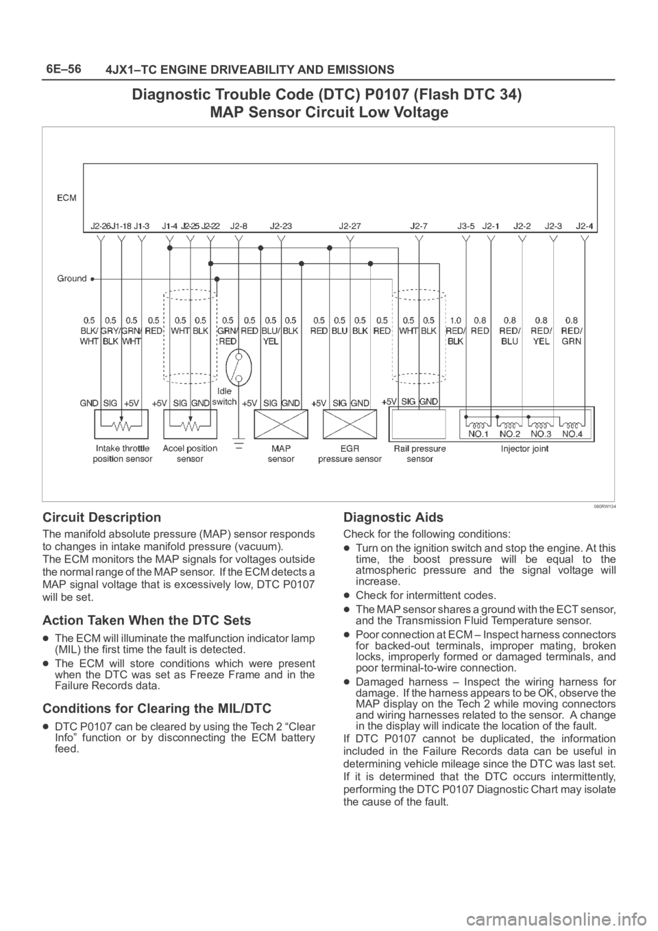
060RW134
Circuit Description
The manifold absolute pressure (MAP) sensor responds
to changes in intake manifold pressure (vacuum).
The ECM monitors the MAP signals for voltages outside
the normal range of the MAP sensor. If the ECM detects a
MAP signal voltage that is excessively low, DTC P0107
will be set.
Action Taken When the DTC Sets
The ECM will illuminate the malfunction indicator lamp
(MIL) the first time the fault is detected.
The ECM will store conditions which were present
when the DTC was set as Freeze Frame and in the
Failure Records data.
Conditions for Clearing the MIL/DTC
DTC P0107 can be cleared by using the Tech 2 “Clear
Info” function or by disconnecting the ECM battery
feed.
Diagnostic Aids
Check for the following conditions:
Turn on the ignition switch and stop the engine. At this
time, the boost pressure will be equal to the
atmospheric pressure and the signal voltage will
increase.
Check for intermittent codes.
The MAP sensor shares a ground with the ECT sensor,
and the Transmission Fluid Temperature sensor.
Poor connection at ECM – Inspect harness connectors
for backed-out terminals, improper mating, broken
locks, improperly formed or damaged terminals, and
poor terminal-to-wire connection.
Damaged harness – Inspect the wiring harness for
damage. If the harness appears to be OK, observe the
MAP display on the Tech 2 while moving connectors
and wiring harnesses related to the sensor. A change
in the display will indicate the location of the fault.
If DTC P0107 cannot be duplicated, the information
included in the Failure Records data can be useful in
determining vehicle mileage since the DTC was last set.
If it is determined that the DTC occurs intermittently,
performing the DTC P0107 Diagnostic Chart may isolate
the cause of the fault.
Page 1950 of 6000

6E–57 4JX1–TC ENGINE DRIVEABILITY AND EMISSIONS
DTC P0107 – MAP Sensor Circuit Low Voltage
StepActionVa l u e ( s )Ye sNo
1Was the “On-Board Diagnostic (OBD) System Check”
performed?
—Go to Step 2
Go to OBD
System
Check
2Put the engine into an idling status.
Is the MAP voltage value displayed on the Tech 2 below
the specified value?
0.25 VGo to Step 3
Refer to
Diagnostic
Aids
and
Symptom
Diagnosis
31. Turn off the ignition switch.
2. Remove the sensor connector connection.
3. Jumper between harness pins “red” and “blue”
wires.
4. Turn on the ignition switch “ON”.
Is the MAP voltage reading above the specified value?
4 VGo to Step 5Go to Step 4
41. Turn off the ignition switch.
2. Remove the jumper wire.
3. Connect the relay & solenoid checker
(5-8840-0386-0) to the battery voltage, then check
the MAP signal circuit (blue wire).
4. Turn on the ignition switch.
Is the value displayed on the Tech 2 above the specified
value?
4 VGo to Step 6Go to Step 7
5Check the terminal connection at the MAP sensor and
repair or replace terminal if necessary.
Is the action complete?
—Verify repair—
6Repair the 5V power circuit (red) harness or Replace
the ECM (Refer to the Data Programming in Case of
ECM change).
Is the action complete?
—Verify repair—
7Repair the signal circuit (blue) harness or Replace the
ECM (Refer to the Data Programming in Case of ECM
change).
Is the action complete?
—Verify repair—