service OPEL FRONTERA 1998 Workshop Manual
[x] Cancel search | Manufacturer: OPEL, Model Year: 1998, Model line: FRONTERA, Model: OPEL FRONTERA 1998Pages: 6000, PDF Size: 97 MB
Page 5039 of 6000
INDUCTION6J–1
ENGINE
INDUCTION
CONTENTS
Service Precaution 6J–1. . . . . . . . . . . . . . . . . . . . . .
Air Cleaner Element 6J–2. . . . . . . . . . . . . . . . . . . . .
Removal 6J–2. . . . . . . . . . . . . . . . . . . . . . . . . . . . .
Inspection 6J–2. . . . . . . . . . . . . . . . . . . . . . . . . . . .
Installation 6J–2. . . . . . . . . . . . . . . . . . . . . . . . . . . .
Service Precaution
WARNING: IF SO EQUIPPED WITH A
SUPPLEMENTAL RESTRAINT SYSTEM
(SRS),REFER TO THE SRS COMPONENT AND
WIRING LOCATION VIEW IN ORDER TO DETERMINE
WHETHER YOU ARE PERFORMING SERVICE ON OR
NEAR THE SRS COMPONENTS OR THE SRS
WIRING. WHEN YOU ARE PERFORMING SERVICE
ON OR NEAR THE SRS COMPONENTS OR THE SRS
WIRING, REFER TO THE SRS SERVICE
INFORMATION. FAILURE TO FOLLOW WARNINGS
COULD RESULT IN POSSIBLE AIR BAG
DEPLOYMENT, PERSONAL INJURY, OR
OTHERWISE UNNEEDED SRS SYSTEM REPAIRS.
CAUTION: Always use the correct fastener in the
proper location. When you replace a fastener, use
ONLY the exact part number for that application.
ISUZU will call out those fasteners that require a
replacement after removal. ISUZU will also call out
the fasteners that require thread lockers or thread
sealant. UNLESS OTHERWISE SPECIFIED, do not
use supplemental coatings (Paints, greases, or other
corrosion inhibitors) on threaded fasteners or
fastener joint interfaces. Generally, such coatings
adversely affect the fastener torque and the joint
clamping force, and may damage the fastener. When
you install fasteners, use the correct tightening
sequence and specifications. Following these
instructions can help you avoid damage to parts and
systems.
Page 5274 of 6000
ENGINE MECHANICAL 6A – 1
ENGINE
ENGINE MECHANICAL
CONTENTS
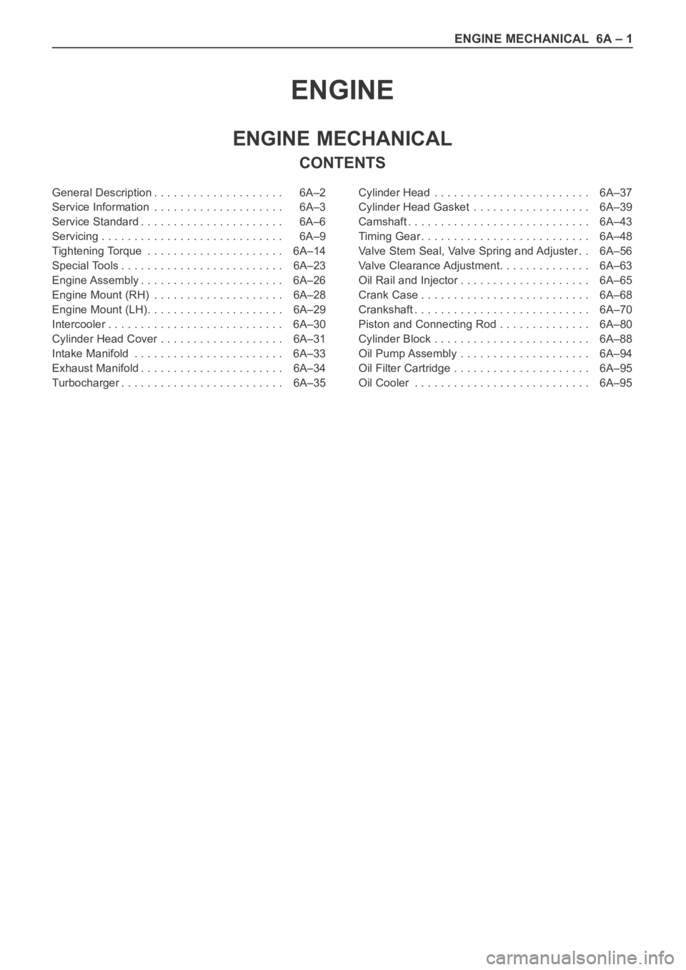
General Description . . . . . . . . . . . . . . . . . . . . 6A–2
Service Information . . . . . . . . . . . . . . . . . . . . 6A–3
Service Standard . . . . . . . . . . . . . . . . . . . . . . 6A–6
Servicing . . . . . . . . . . . . . . . . . . . . . . . . . . . . 6A–9
Tightening Torque . . . . . . . . . . . . . . . . . . . . . 6A–14
Special Tools . . . . . . . . . . . . . . . . . . . . . . . . . 6A–23
Engine Assembly . . . . . . . . . . . . . . . . . . . . . . 6A–26
Engine Mount (RH) . . . . . . . . . . . . . . . . . . . . 6A–28
Engine Mount (LH). . . . . . . . . . . . . . . . . . . . . 6A–29
Intercooler . . . . . . . . . . . . . . . . . . . . . . . . . . . 6A–30
Cylinder Head Cover . . . . . . . . . . . . . . . . . . . 6A–31
Intake Manifold . . . . . . . . . . . . . . . . . . . . . . . 6A–33
Exhaust Manifold . . . . . . . . . . . . . . . . . . . . . . 6A–34
Turbocharger . . . . . . . . . . . . . . . . . . . . . . . . . 6A–35Cylinder Head . . . . . . . . . . . . . . . . . . . . . . . . 6A–37
Cylinder Head Gasket . . . . . . . . . . . . . . . . . . 6A–39
Camshaft . . . . . . . . . . . . . . . . . . . . . . . . . . . . 6A–43
Timing Gear . . . . . . . . . . . . . . . . . . . . . . . . . . 6A–48
Valve Stem Seal, Valve Spring and Adjuster . . 6A–56
Valve Clearance Adjustment. . . . . . . . . . . . . . 6A–63
Oil Rail and Injector . . . . . . . . . . . . . . . . . . . . 6A–65
Crank Case . . . . . . . . . . . . . . . . . . . . . . . . . . 6A–68
Crankshaft . . . . . . . . . . . . . . . . . . . . . . . . . . . 6A–70
Piston and Connecting Rod . . . . . . . . . . . . . . 6A–80
Cylinder Block . . . . . . . . . . . . . . . . . . . . . . . . 6A–88
Oil Pump Assembly . . . . . . . . . . . . . . . . . . . . 6A–94
Oil Filter Cartridge . . . . . . . . . . . . . . . . . . . . . 6A–95
Oil Cooler . . . . . . . . . . . . . . . . . . . . . . . . . . . 6A–95
Page 5276 of 6000
ENGINE MECHANICAL 6A – 3
SERVICE INFORMATION
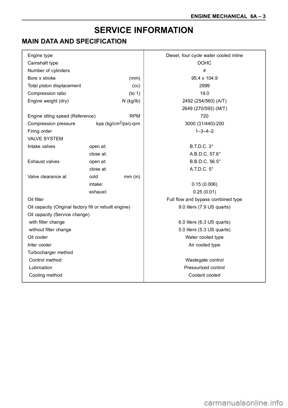
MAIN DATA AND SPECIFICATION
Engine type Diesel, four cycle water cooled inline
Camshaft type DOHC
Number of cylinders 4
Bore x stroke (mm) 95.4 x 104.9
Total piston displacement (cc) 2999
Compression ratio (to 1) 19.0
Engine weight (dry) N (kg/lb) 2492 (254/560) (A/T)
2649 (270/593) (M/T)
Engine idling speed (Reference) RPM 720
Compression pressure kpa (kg/cm
2/psi)-rpm 3000 (31/440)-200
Firing order 1–3–4–2
VALVE SYSTEM
Intake valves open at: B.T.D.C. 3°
close at: A.B.D.C. 57.6°
Exhaust valves open at: B.B.D.C. 56.5°
close at: A.T.D.C. 5°
Valve clearance at cold mm (in)
intake: 0.15 (0.006)
exhaust: 0.25 (0.01)
Oil filter Full flow and bypass combined type
Oil capacity (Original factory fill or rebuilt engine) 9.0 liters (7.9 US quarts)
Oil capacity (Service change)
with filter change 6.0 liters (6.3 US quarts)
without filter change 5.0 liters (5.3 US quarts)
Oil cooler Water cooled type
Inter cooler Air cooled type
Turbocharger method
Control method Wastegate control
Lubrication Pressurized control
Cooling method Coolant cooled
Page 5279 of 6000
6A – 6 ENGINE MECHANICAL
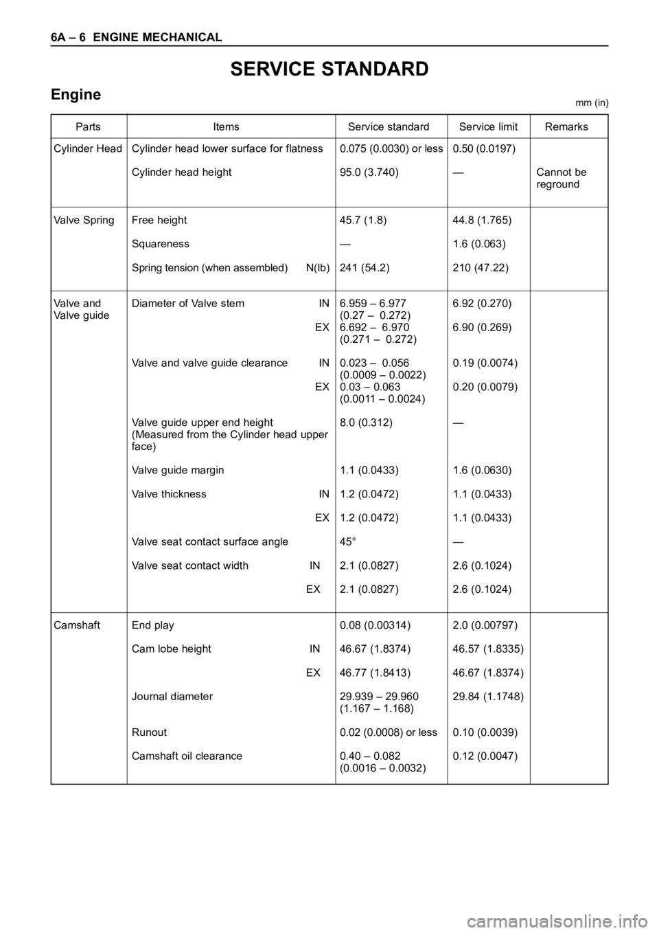
SERVICE STANDARD
Enginemm (in)
Parts Items Service standard Service limit Remarks
Cylinder Head
Va l v e S p r i n g
Valve and
Valve guide
Camshaft0.075 (0.0030) or less
95.0 (3.740)
45.7 (1.8)
—
241 (54.2)
6.959 – 6.977
(0.27 – 0.272)
6.692 – 6.970
(0.271 – 0.272)
0.023 – 0.056
(0.0009 – 0.0022)
0.03 – 0.063
(0.0011 – 0.0024)
8.0 (0.312)
1.1 (0.0433)
1.2 (0.0472)
1.2 (0.0472)
45°
2.1 (0.0827)
2.1 (0.0827)
0.08 (0.00314)
46.67 (1.8374)
46.77 (1.8413)
29.939 – 29.960
(1.167 – 1.168)
0.02 (0.0008) or less
0.40 – 0.082
(0.0016 – 0.0032)0.50 (0.0197)
—
44.8 (1.765)
1.6 (0.063)
210 (47.22)
6.92 (0.270)
6.90 (0.269)
0.19 (0.0074)
0.20 (0.0079)
—
1.6 (0.0630)
1.1 (0.0433)
1.1 (0.0433)
—
2.6 (0.1024)
2.6 (0.1024)
2.0 (0.00797)
46.57 (1.8335)
46.67 (1.8374)
29.84 (1.1748)
0.10 (0.0039)
0.12 (0.0047)Cannot be
reground Cylinder head lower surface for flatness
Cylinder head height
Free height
Squareness
Spring tension (when assembled) N(lb)
Diameter of Valve stem IN
EX
Valve and valve guide clearance IN
EX
Valve guide upper end height
(Measured from the Cylinder head upper
face)
Valve guide margin
Valve thickness IN
EX
Valve seat contact surface angle
Valve seat contact width IN
EX
End play
Cam lobe height IN
EX
Journal diameter
Runout
Camshaft oil clearance
Page 5280 of 6000
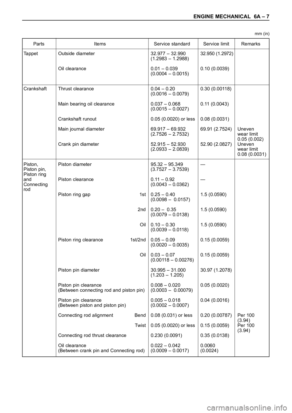
ENGINE MECHANICAL 6A – 7
Parts Items Service standard Service limit Remarks
Tappet
Crankshaft
Piston,
Piston pin,
Piston ring
and
Connecting
rod32.977 – 32.990
(1.2983 – 1.2988)
0.01 – 0.039
(0.0004 – 0.0015)
0.04 – 0.20
(0.0016 – 0.0079)
0.037 – 0.068
(0.0015 – 0.0027)
0.05 (0.0020) or less
69.917 – 69.932
(2.7526 – 2.7532)
52.915 – 52.930
(2.0933 – 2.0839)
95.32 – 95.349
(3.7527 – 3.7539)
0.11 – 0.92
(0.0043 – 0.0362)
0.25 – 0.40
(0.0098 – 0.0157)
0.20 – 0.35
(0.0079 – 0.0138)
0.10 – 0.30
(0.0039 – 0.0118)
0.05 – 0.09
(0.0020 – 0.0035)
0.03 – 0.07
(0.00118 – 0.00276)
30.995 – 31.000
(1.203 – 1.205)
0.008 – 0.020
(0.0003 – 0.00079)
0.005 – 0.018
(0.0002 – 0.0007)
0.08 (0.031) or less
0.05 (0.0020) or less
0.230 (0.0091)
0.022 – 0.042
(0.0009 – 0.0017)32.950 (1.2972)
0.10 (0.0039)
0.30 (0.00118)
0.11 (0.0043)
0.08 (0.0031)
69.91 (2.7524)
52.90 (2.0827)
—
—
1.5 (0.0590)
1.5 (0.0590)
1.5 (0.0590)
0.15 (0.0059)
0.15 (0.0059)
30.97 (1.2078)
0.05 (0.0020)
0.04 (0.0016)
0.20 (0.00787)
0.15 (0.0059)
0.35 (0.0138)
0.0060
(0.0024)Uneven
wear limit
0.05 (0.002)
Uneven
wear limit
0.08 (0.0031)
Per 100
(3.94)
Per 100
(3.94) Outside diameter
Oil clearance
Thrust clearance
Main bearing oil clearance
Crankshaft runout
Main journal diameter
Crank pin diameter
Piston diameter
Piston clearance
Piston ring gap 1st
2nd
Oil
Piston ring clearance 1st/2nd
Oil
Piston pin diameter
Piston pin clearance
(Between connecting rod and piston pin)
Piston pin clearance
(Between piston and piston pin)
Connecting rod alignment Bend
Twi st
Connecting rod thrust clearance
Oil clearance
(Between crank pin and Connecting rod)
mm (in)
Page 5281 of 6000
6A – 8 ENGINE MECHANICAL
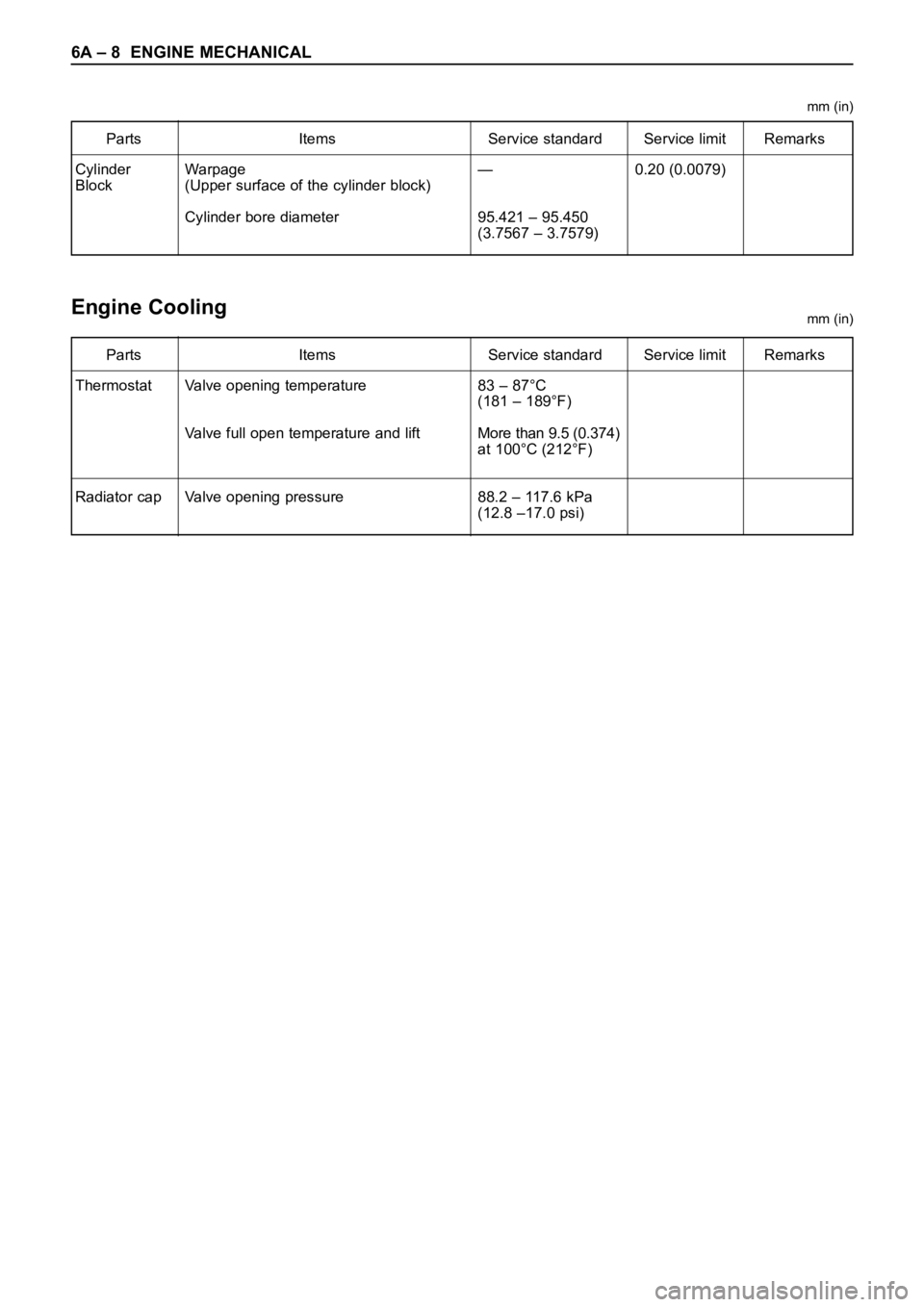
Parts Items Service standard Service limit Remarks
Cylinder
Block—
95.421 – 95.450
(3.7567 – 3.7579)0.20 (0.0079) Warpage
(Upper surface of the cylinder block)
Cylinder bore diameter
Parts Items Service standard Service limit Remarks
Thermostat
Radiator cap83 – 87°C
(181 – 189°F)
More than 9.5 (0.374)
at 100°C (212°F)
88.2 – 117.6 kPa
(12.8 –17.0 psi) Valve opening temperature
Valve full open temperature and lift
Valve opening pressure
Engine Coolingmm (in) mm (in)
Page 5282 of 6000
ENGINE MECHANICAL 6A – 9
SERVICING
Servicing refers to general maintenance procedures to
be performed by qualified service personnel.
MODEL IDENTIFICATION
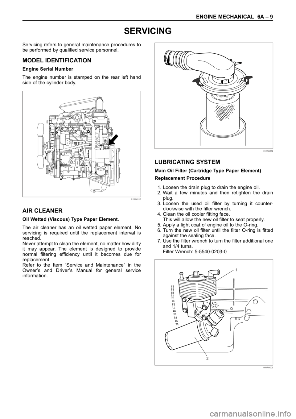
Engine Serial Number
The engine number is stamped on the rear left hand
side of the cylinder body.
AIR CLEANER
Oil Wetted (Viscous) Type Paper Element.
The air cleaner has an oil wetted paper element. No
servicing is required until the replacement interval is
reached.
Never attempt to clean the element, no matter how dirty
it may appear. The element is designed to provide
normal filtering efficiency until it becomes due for
replacement.
Refer to the Item “Service and Maintenance” in the
Owner’s and Driver’s Manual for general service
information.
LUBRICATING SYSTEM
Main Oil Filter (Cartridge Type Paper Element)
Replacement Procedure
1. Loosen the drain plug to drain the engine oil.
2. Wait a few minutes and then retighten the drain
plug.
3. Loosen the used oil filter by turning it counter-
clockwise with the filter wrench.
4. Clean the oil cooler fitting face.
This will allow the new oil filter to seat properly.
5. Apply a light coat of engine oil to the O-ring.
6. Turn the new oil filter until the filter O-ring is fitted
against the sealing face.
7. Use the filter wrench to turn the filter additional one
and 1/4 turns.
Filter Wrench: 5-5540-0203-0
012RW115
012RW062
1
2
050RW009
Page 5363 of 6000
6A – 90 ENGINE MECHANICAL
Cylinder Bore Measurement
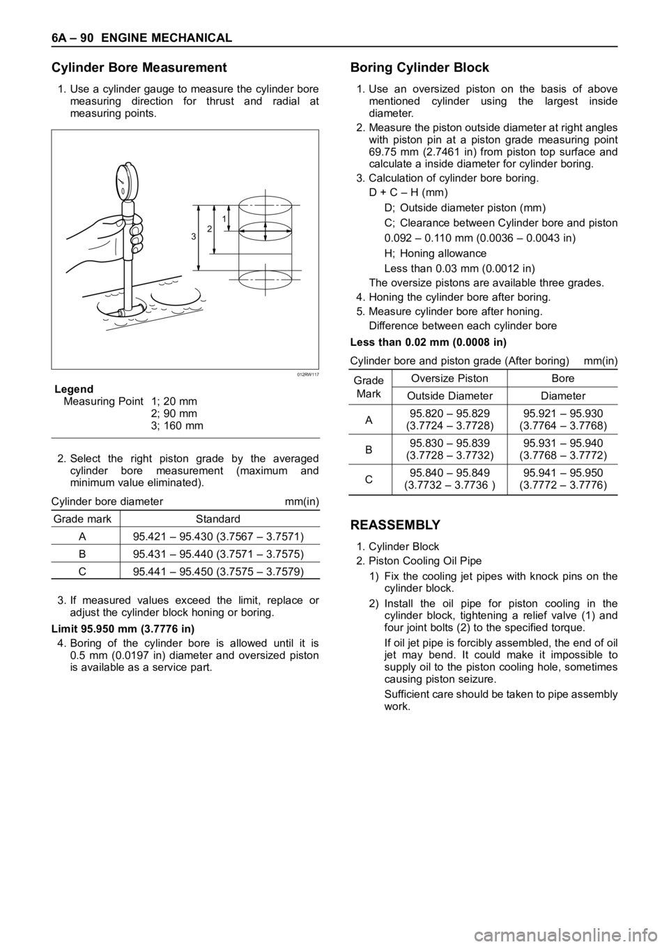
1. Use a cylinder gauge to measure the cylinder bore
measuring direction for thrust and radial at
measuring points.
Legend
Measuring Point 1; 20 mm
2; 90 mm
3; 160 mm
2. Select the right piston grade by the averaged
cylinder bore measurement (maximum and
minimum value eliminated).
Cylinder bore diameter mm(in)
Grade mark Standard
A 95.421 – 95.430 (3.7567 – 3.7571)
B 95.431 – 95.440 (3.7571 – 3.7575)
C 95.441 – 95.450 (3.7575 – 3.7579)
3. If measured values exceed the limit, replace or
adjust the cylinder block honing or boring.
Limit 95.950 mm (3.7776 in)
4. Boring of the cylinder bore is allowed until it is
0.5 mm (0.0197 in) diameter and oversized piston
is available as a service part.
Boring Cylinder Block
1. Use an oversized piston on the basis of above
mentioned cylinder using the largest inside
diameter.
2. Measure the piston outside diameter at right angles
with piston pin at a piston grade measuring point
69.75 mm (2.7461 in) from piston top surface and
calculate a inside diameter for cylinder boring.
3. Calculation of cylinder bore boring.
D + C – H (mm)
D; Outside diameter piston (mm)
C; Clearance between Cylinder bore and piston
0.092 – 0.110 mm (0.0036 – 0.0043 in)
H; Honing allowance
Less than 0.03 mm (0.0012 in)
The oversize pistons are available three grades.
4. Honing the cylinder bore after boring.
5. Measure cylinder bore after honing.
Difference between each cylinder bore
Less than 0.02 mm (0.0008 in)
Cylinder bore and piston grade (After boring) mm(in)
GradeOversize Piston Bore
Mark
Outside Diameter Diameter
A95.820 – 95.829 95.921 – 95.930
(3.7724 – 3.7728) (3.7764 – 3.7768)
B95.830 – 95.839 95.931 – 95.940
(3.7728 – 3.7732) (3.7768 – 3.7772)
C95.840 – 95.849 95.941 – 95.950
(3.7732 – 3.7736 ) (3.7772 – 3.7776)
REASSEMBLY
1. Cylinder Block
2. Piston Cooling Oil Pipe
1) Fix the cooling jet pipes with knock pins on the
cylinder block.
2) Install the oil pipe for piston cooling in the
cylinder block, tightening a relief valve (1) and
four joint bolts (2) to the specified torque.
If oil jet pipe is forcibly assembled, the end of oil
jet may bend. It could make it impossible to
supply oil to the piston cooling hole, sometimes
causing piston seizure.
Sufficient care should be taken to pipe assembly
work.
321
012RW117
Page 5370 of 6000
ENGINE COOLING 6B – 1
ENGINE COOLING
CONTENTS
General Description . . . . . . . . . . . . . . . . . . 6B–2
On-Vehicle Service . . . . . . . . . . . . . . . . . . . 6B–6
Water Pump . . . . . . . . . . . . . . . . . . . . . . 6B–6Thermostat . . . . . . . . . . . . . . . . . . . . . . . 6B–7
Radiator . . . . . . . . . . . . . . . . . . . . . . . . . 6B–9
Drive Belt Adjustment . . . . . . . . . . . . . . . 6B–11
Page 5375 of 6000
6B – 6 ENGINE COOLING
REMOVAL
1. Drain coolant.
2. AC Generator Drive Belt
1) Loosen AC Generator mounting bolt, adjust
plate lock bolt, and remove the drive belt.
3. Cooling Fan Assembly
1) Remove lock nut and take out cooling fan
assembly with cooling fan clutch.
4. Water Pump Assembly
INSPECTION
Make necessary repair and parts replacement if
excessive wear or damage is found during inspection.
Should any of the following problems occur, the entire
water pump assembly must be replaced.
1) Cracks in the water pump body
2) Coolant leakage from the seal unit
3) Play or abnormal noise in the bearing
4) Cracks or corrosion in the impeller
INSTALLATION
1. Gasket
1) Set gasket to gear case.
2. Water Pump Assembly
1) Install water pump assembly, and tighten to
specified torque.
Torque: 20 Nꞏm (2.0 kgꞏm/14.5 lb ft)3. Cooling Fan Assembly
1) Install cooling fan assembly, and tighten to
specified torque.
Torque: 8 Nꞏm (0.8 kgꞏm/5.8 lb ft)
4. AC Generator Drive Belt
1) Install AC Generator drive belt and adjust belt
tension.
Torque: 40 Nꞏm (4.1 kgꞏm/29.7 lb ft)
For ACG to bracket
20 Nꞏm (2.0 kgꞏm/14.5 lb ft)
For ACG to adjust plate
5. Fill coolant to specified capacity.
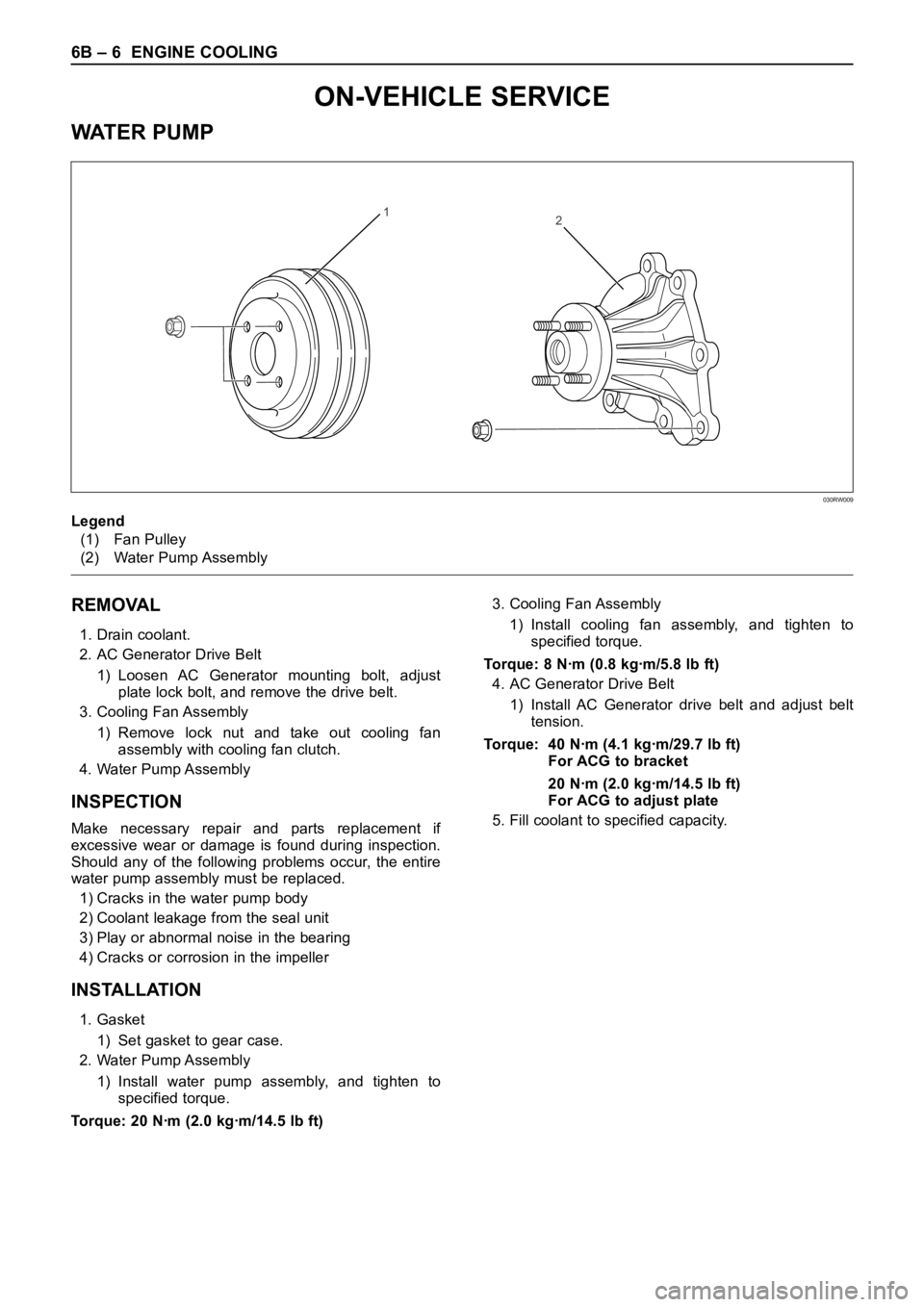
12
Legend
(1) Fan Pulley
(2) Water Pump Assembly
030RW009
ON-VEHICLE SERVICE
WAT E R P U M P