service OPEL FRONTERA 1998 Workshop Manual
[x] Cancel search | Manufacturer: OPEL, Model Year: 1998, Model line: FRONTERA, Model: OPEL FRONTERA 1998Pages: 6000, PDF Size: 97 MB
Page 4727 of 6000

6E–70
ENGINE DRIVEABILITY AND EMISSIONS
SPARK — Tech 2 Range –64 to 64 —
Displays the amount of spark advance being commanded
by the PCM on the IC circuit.
START-UP ECT — Tech 2 Range –40
C to 151C
(–40
F to 304F) —
Indicates the engine coolant temperature at the time that
the vehicle was started. Used by the HO2S diagnostic to
determine if the last start-up was a cold start.
START-UP IAT — Tech 2 Range –40
C to 151C
(–40
F to 304F) —
Indicates the intake air temperature at the time that the
vehicle was started. Used by the HO2S diagnostic to
determine if the last start-up was a cold start.
TP — Tech 2 Range 0%-100% —
TP (throttle position) angle is computed by the PCM from
the TP sensor voltage. TP angle should display “0%” at
idle and “100%” at wide open throttle.
TP SENSOR — Tech 2 Range 0.00-5.00 Volts —
The voltage being monitored by the PCM on the TP
sensor signal circuit.
CATALYST PROTECTION MODE — Tech 2 Displays
YES or NO —
“YES” displayed indicates that the PCM has detected
conditions appropriate to operate in TWC protection
mode. The PCM will decrease the air/fuel ratio to a value
that depends on mass air flow (higher mass air flow =
lower air/fuel ratio).
UPSHIFT LAMP (MANUAL TRANSMISSION)
VEHICLE SPEED — Tech 2 Range 0-255 km/h
(0-155 mph) —
The vehicle speed sensor signal is converted into km/h
and mph for display.
WEAK CYLINDER — Tech 2 Displays Cylinder
Number —
This indicates that the PCM has detected crankshaft
speed variations that indicate 2% or more cylinder firing
events are misfires.
Typical Scan Data Values
Use the Typical Scan Data Values Table only after the
On-Board Diagnostic System Check has been
completed, no DTC(s) were noted, and you have
determined that the on-board diagnostics are functioning
properly. Tech 2 values from a properly-running engine
may be used for comparison with the engine you are
diagnosing. The typical scan data values represent
values that would be seen on a normally-running engine.
NOTE: A Tech 2 that displays faulty data should not be
used, and the problem should be reported to the Tech 2
manufacturer. Use of a faulty Tech 2 can result in
misdiagnosis and unnecessary replacement of parts.
Only the parameters listed below are referred to in this
service manual for use in diagnosis. For further
information on using the Tech 2 to diagnose the PCM and
related sensors, refer to the applicable reference section
listed below. If all values are within the typical range
described below, refer to the
Symptoms section for
diagnosis.
Test Conditions
Engine running, lower radiator hose hot, transmission in
park or neutral, closed loop, accessaries off, brake not
applied and air conditioning off.
Page 4733 of 6000
6E–76
ENGINE DRIVEABILITY AND EMISSIONS
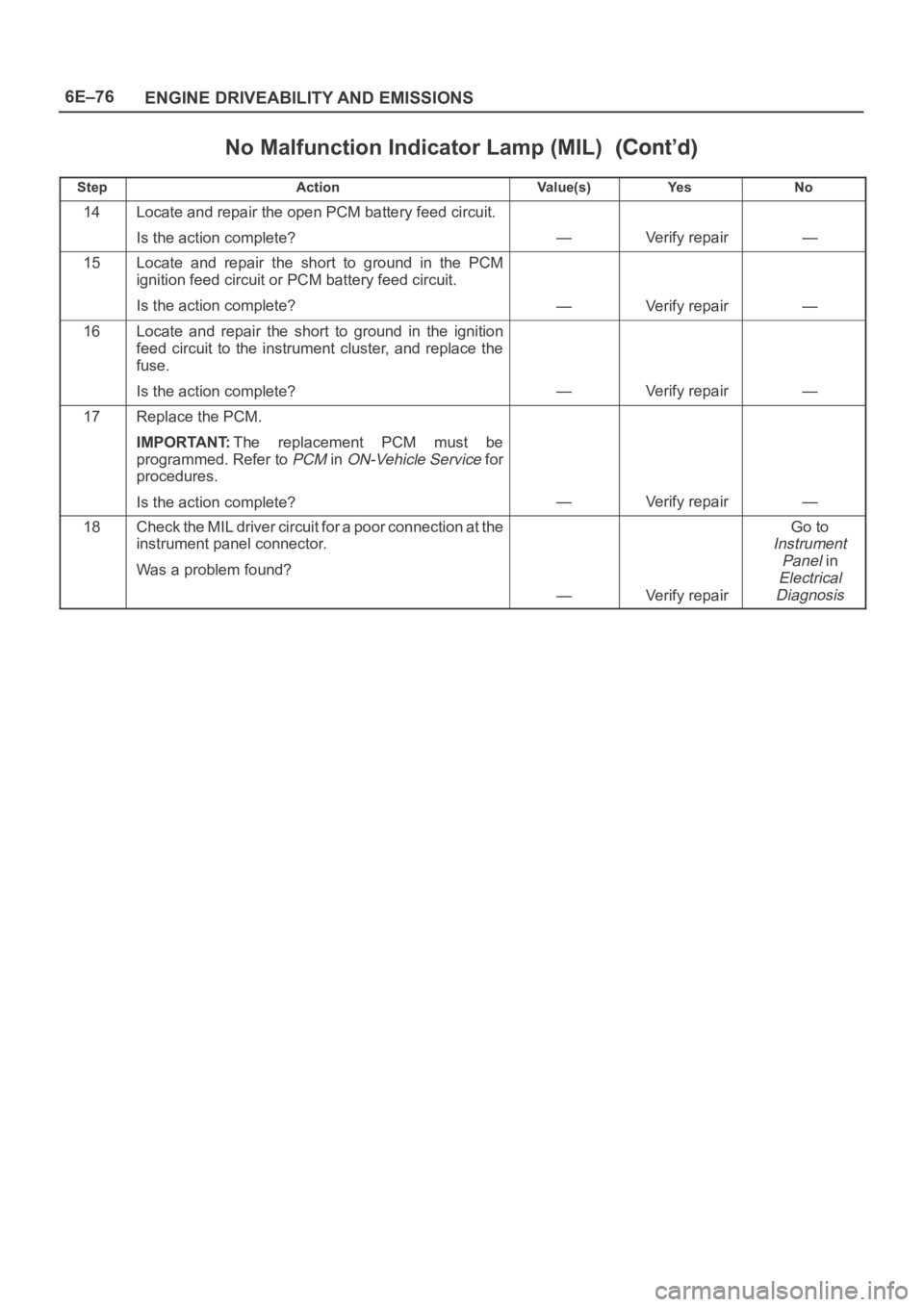
No Malfunction Indicator Lamp (MIL)
StepNo Ye s Va l u e ( s ) Action
14Locate and repair the open PCM battery feed circuit.
Is the action complete?
—Verify repair—
15Locate and repair the short to ground in the PCM
ignition feed circuit or PCM battery feed circuit.
Is the action complete?
—Verify repair—
16Locate and repair the short to ground in the ignition
feed circuit to the instrument cluster, and replace the
fuse.
Is the action complete?
—Verify repair—
17Replace the PCM.
IMPORTANT:The replacement PCM must be
programmed. Refer to
PCM in ON-Vehicle Service for
procedures.
Is the action complete?
—Verify repair—
18Check the MIL driver circuit for a poor connection at the
instrument panel connector.
Was a problem found?
—Verify repair
Go to
Instrument
Panel
in
Electrical
Diagnosis
Page 4735 of 6000
6E–78
ENGINE DRIVEABILITY AND EMISSIONS
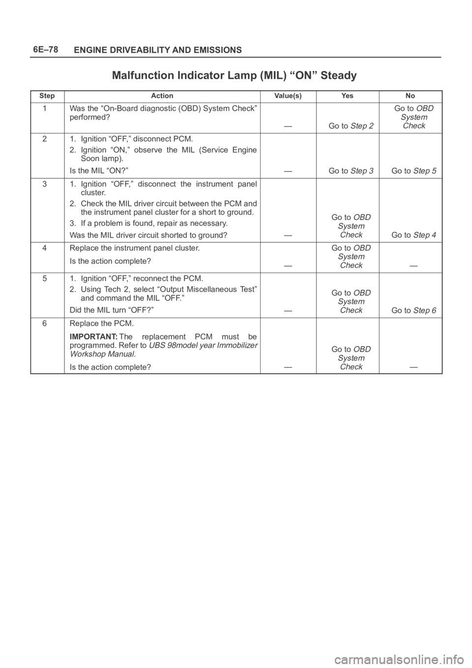
Malfunction Indicator Lamp (MIL) “ON” Steady
StepActionVa l u e ( s )Ye sNo
1Was the “On-Board diagnostic (OBD) System Check”
performed?
—Go to Step 2
Go to OBD
System
Check
21. Ignition “OFF,” disconnect PCM.
2. Ignition “ON,” observe the MIL (Service Engine
Soon lamp).
Is the MIL “ON?”
—Go to Step 3Go to Step 5
31. Ignition “OFF,” disconnect the instrument panel
cluster.
2. Check the MIL driver circuit between the PCM and
the instrument panel cluster for a short to ground.
3. If a problem is found, repair as necessary.
Was the MIL driver circuit shorted to ground?
—
Go to OBD
System
Check
Go to Step 4
4Replace the instrument panel cluster.
Is the action complete?
—
Go to OBD
System
Check
—
51. Ignition “OFF,” reconnect the PCM.
2. Using Tech 2, select “Output Miscellaneous Test”
and command the MIL “OFF.”
Did the MIL turn “OFF?”
—
Go to OBD
System
Check
Go to Step 6
6Replace the PCM.
IMPORTANT:The replacement PCM must be
programmed. Refer to
UBS 98model year Immobilizer
Workshop Manual.
Is the action complete?—
Go to OBD
System
Check
—
Page 4746 of 6000
6E–89 ENGINE DRIVEABILITY AND EMISSIONS
The valve or valve seat within the fuel pressure
regulator.
The fuel injector(s).
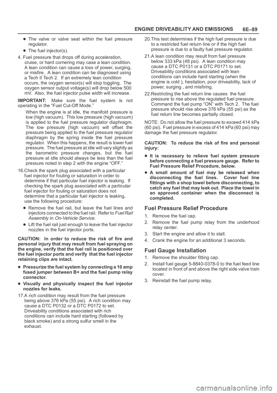
4. Fuel pressure that drops off during acceleration,
cruise, or hard cornering may case a lean condition.
A lean condition can cause a loss of power, surging,
or misfire. A lean condition can be diagnosed using
a Tech II Tech 2. If an extremely lean condition
occurs, the oxygen sensor(s) will stop toggling. The
oxygen sensor output voltage(s) will drop below 500
mV. Also, the fuel injector pulse width will increase.
IMPORTANT:Make sure the fuel system is not
operating in the “Fuel Cut-Off Mode.”
When the engine is at idle, the manifold pressure is
low (high vacuum). This low pressure (high vacuum)
is applied to the fuel pressure regulator diaphragm.
The low pressure (high vacuum) will offset the
pressure being applied to the fuel pressure regulator
diaphragm by the spring inside the fuel pressure
regulator. When this happens, the result is lower fuel
pressure. The fuel pressure at idle will vary slightly as
the barometric pressure changes, but the fuel
pressure at idle should always be less than the fuel
pressure noted in step 2 with the engine “OFF.”
16.Check the spark plug associated with a particular
fuel injector for fouling or saturation in order to
determine if that particular fuel injector is leaking. If
checking the spark plug associated with a particular
fuel injector for fouling or saturation does not
determine that a particular fuel injector is leaking,
use the following procedure:
Remove the fuel rail, but leave the fuel lines and
injectors connected to the fuel rail. Refer to
Fuel Rail
Assembly
in On-Vehicle Service.
Lift the fuel rail just enough to leave the fuel injector
nozzles in the fuel injector ports.
CAUTION: In order to reduce the risk of fire and
personal injury that may result from fuel spraying on
the engine, verify that the fuel rail is positioned over
the fuel injector ports and verify that the fuel injector
retaining clips are intact.
Pressurize the fuel system by connecting a 10 amp
fused jumper between B+ and the fuel pump relay
connector.
Visually and physically inspect the fuel injector
nozzles for leaks.
17.A rich condition may result from the fuel pressure
being above 376 kPa (55 psi). A rich condition may
cause a DTC P0132 or a DTC P0172 to set.
Driveability conditions associated with rich
conditions can include hard starting (followed by
black smoke) and a strong sulfur smell in the
exhaust.20.This test determines if the high fuel pressure is due
to a restricted fuel return line or if the high fuel
pressure is due to a faulty fuel pressure regulator.
21.A lean condition may result from fuel pressure
below 333 kPa (48 psi). A lean condition may
cause a DTC P0131 or a DTC P0171 to set.
Driveability conditions associated with lean
conditions can include hard starting (when the
engine is cold ), hesitation, poor driveability, lack of
power, surging , and misfiring.
22.Restricting the fuel return line causes the fuel
pressure to rise above the regulated fuel pressure.
Command the fuel pump “ON” with Tech 2. The fuel
pressure should rise above 376 kPa (55 psi) as the
fuel return line becomes partially closed.
NOTE: Do not allow the fuel pressure to exceed 414 kPa
( 6 0 p s i ) . F u e l p r e s s u r e i n e x c e s s o f 4 1 4 k P a ( 6 0 p s i ) m a y
damage the fuel pressure regulator.
CAUTION: To reduce the risk of fire and personal
injury:
It is necessary to relieve fuel system pressure
before connecting a fuel pressure gauge. Refer to
Fuel Pressure Relief Procedure, below.
A small amount of fuel may be released when
disconnecting the fuel lines. Cover fuel line
fittings with a shop towel before disconnecting, to
catch any fuel that may leak out. Place the towel in
an approved container when the disconnect is
completed.
Fuel Pressure Relief Procedure
1. Remove the fuel cap.
2. Remove the fuel pump relay from the underhood
relay center.
3. Start the engine and allow it to stall.
4. Crank the engine for an additional 3 seconds.
Fuel Gauge Installation
1. Remove the shoulder fitting cap.
2. Install fuel gauge 5-8840-0378-0 to the fuel feed line
located in front of and above the right side valve train
cover.
3. Reinstall the fuel pump relay.
Page 4751 of 6000

6E–94
ENGINE DRIVEABILITY AND EMISSIONS
Idle Air Control (IAC) System Check
StepActionVa l u e ( s )Ye sNo
11. Ignition “OFF.”
2. Connect the Tech 2.
3. Set the parking brake.
4. Block the wheels.
5. Turn the air conditioning “OFF.”
6. Idle the engine in Park (A/T) or Neutral (M/T).
7. Operate the IAC test.
8. The engine speed should decrease and increase as
the IAC is cycled.
Does the RPM change?
—Go to Step 2Go to Step 3
2RPM should change smoothly.
Does the RPM change within the range specified?700-1500
RPM
—Go to Step 3
3Check the IAC passages.
Are the IAC passages OK?
—Go to Step 4Go to Step 5
4Clear any obstruction from the IAC passages.
Is the action complete?
—Verify repair—
5Replace the IAC. Refer to On-Vehicle Service, Idle Air
Control Valve.
Is the action complete?—Verify repair—
Page 4757 of 6000
6E–100
ENGINE DRIVEABILITY AND EMISSIONS
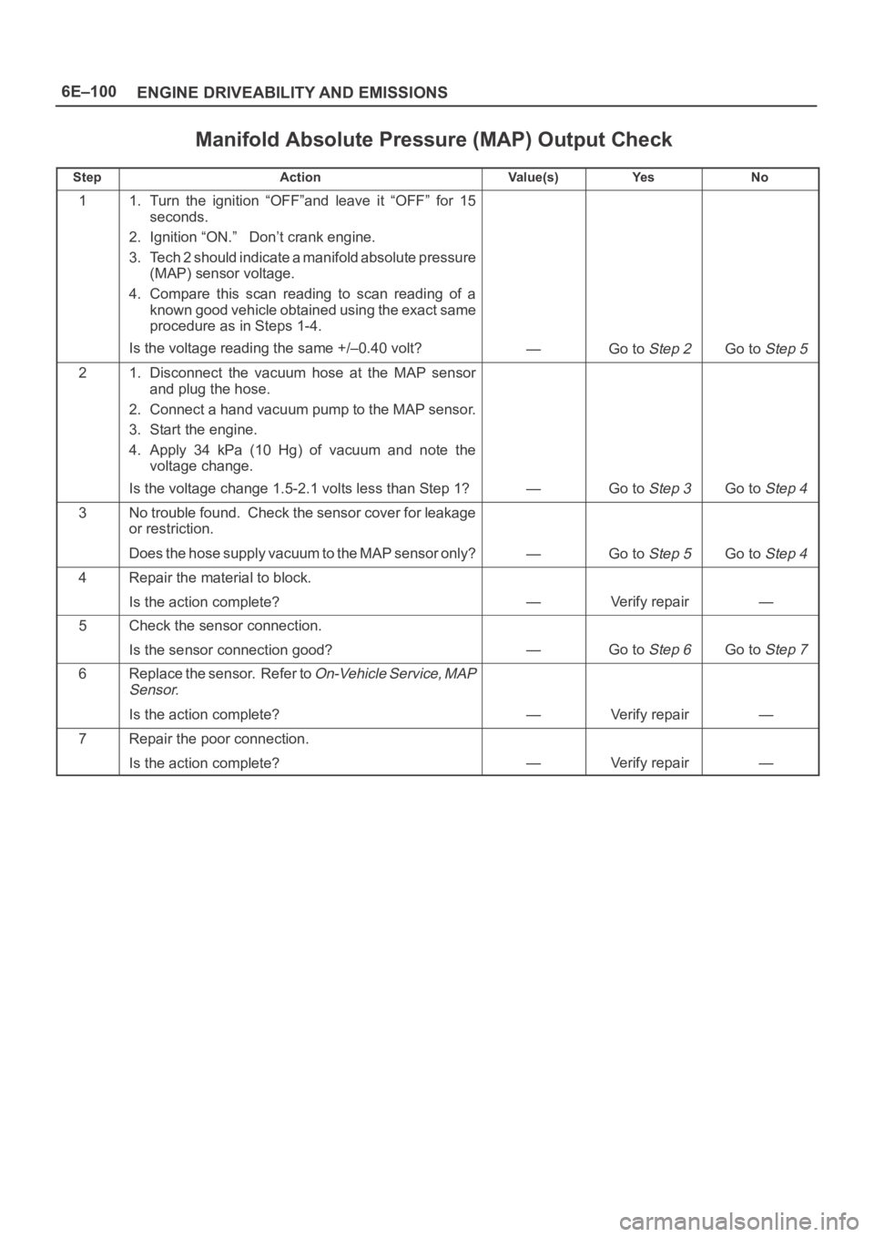
Manifold Absolute Pressure (MAP) Output Check
StepActionVa l u e ( s )Ye sNo
11. Turn the ignition “OFF”and leave it “OFF” for 15
seconds.
2. Ignition “ON.” Don’t crank engine.
3. Tech 2 should indicate a manifold absolute pressure
(MAP) sensor voltage.
4. Compare this scan reading to scan reading of a
known good vehicle obtained using the exact same
procedure as in Steps 1-4.
Is the voltage reading the same +/–0.40 volt?
—Go to Step 2Go to Step 5
21. Disconnect the vacuum hose at the MAP sensor
and plug the hose.
2. Connect a hand vacuum pump to the MAP sensor.
3. Start the engine.
4. Apply 34 kPa (10 Hg) of vacuum and note the
voltage change.
Is the voltage change 1.5-2.1 volts less than Step 1?
—Go to Step 3Go to Step 4
3No trouble found. Check the sensor cover for leakage
or restriction.
Does the hose supply vacuum to the MAP sensor only?
—Go to Step 5Go to Step 4
4Repair the material to block.
Is the action complete?
—Verify repair—
5Check the sensor connection.
Is the sensor connection good?
—Go to Step 6Go to Step 7
6Replace the sensor. Refer to On-Vehicle Service, MAP
Sensor.
Is the action complete?—Verify repair—
7Repair the poor connection.
Is the action complete?
—Verify repair—
Page 4761 of 6000
6E–104
ENGINE DRIVEABILITY AND EMISSIONS
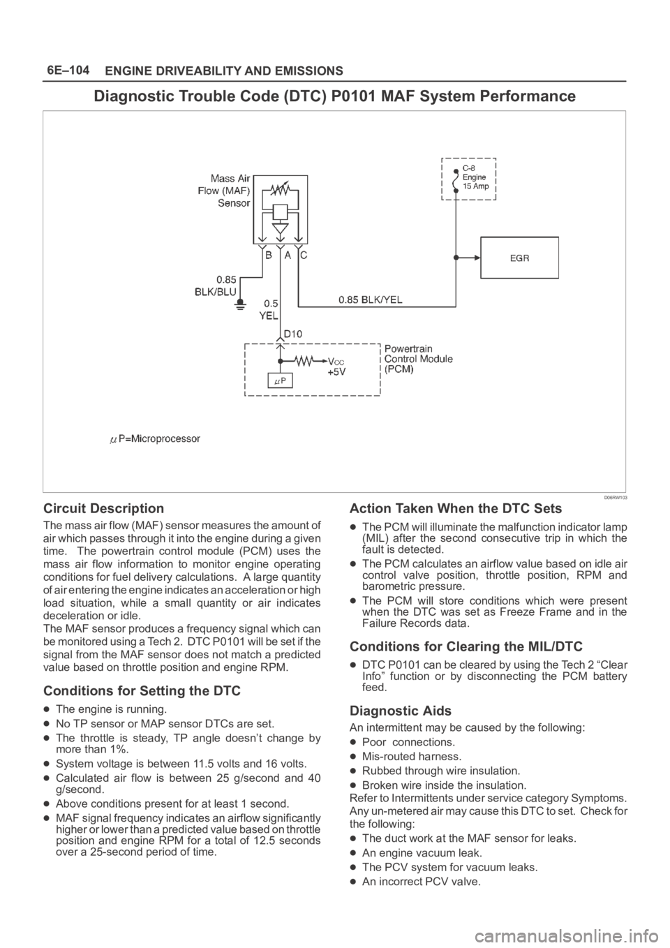
Diagnostic Trouble Code (DTC) P0101 MAF System Performance
D06RW103
Circuit Description
The mass air flow (MAF) sensor measures the amount of
air which passes through it into the engine during a given
time. The powertrain control module (PCM) uses the
mass air flow information to monitor engine operating
conditions for fuel delivery calculations. A large quantity
of air entering the engine indicates an acceleration or high
load situation, while a small quantity or air indicates
deceleration or idle.
The MAF sensor produces a frequency signal which can
be monitored using a Tech 2. DTC P0101 will be set if the
signal from the MAF sensor does not match a predicted
value based on throttle position and engine RPM.
Conditions for Setting the DTC
The engine is running.
No TP sensor or MAP sensor DTCs are set.
The throttle is steady, TP angle doesn’t change by
more than 1%.
System voltage is between 11.5 volts and 16 volts.
Calculated air flow is between 25 g/second and 40
g/second.
Above conditions present for at least 1 second.
MAF signal frequency indicates an airflow significantly
higher or lower than a predicted value based on throttle
position and engine RPM for a total of 12.5 seconds
over a 25-second period of time.
Action Taken When the DTC Sets
The PCM will illuminate the malfunction indicator lamp
(MIL) after the second consecutive trip in which the
fault is detected.
The PCM calculates an airflow value based on idle air
control valve position, throttle position, RPM and
barometric pressure.
The PCM will store conditions which were present
when the DTC was set as Freeze Frame and in the
Failure Records data.
Conditions for Clearing the MIL/DTC
DTC P0101 can be cleared by using the Tech 2 “Clear
Info” function or by disconnecting the PCM battery
feed.
Diagnostic Aids
An intermittent may be caused by the following:
Poor connections.
Mis-routed harness.
Rubbed through wire insulation.
Broken wire inside the insulation.
Refer to Intermittents under service category Symptoms.
Any un-metered air may cause this DTC to set. Check for
the following:
The duct work at the MAF sensor for leaks.
An engine vacuum leak.
The PCV system for vacuum leaks.
An incorrect PCV valve.
Page 4910 of 6000

6E–253 ENGINE DRIVEABILITY AND EMISSIONS
DTC P1508 – IAC System Low RPM
StepNo Ye s Va l u e ( s ) Action
5Visually/physically inspect for following conditions:
Restricted air intake system. Check for a possible
collapsed air intake duct, restricted air filter
element, or foreign objects blocking the air intake
system.
T h r o t t l e b o d y. C h e c k f o r o b j e c t s b l o c k i n g t h e I A C
passage or throttle bore, excessive deposits in
the IAC passage and on the IAC pintle, and
excessive deposits in the throttle bore and on the
throttle plate.
Do any of the above require a repair?
—
Refer to
appropriate
section for
on-vehicle
service
Go to Step 6
61. Check for a poor connection at the IAC harness
connector.
2. If a problem is found, replace faulty terminals as
necessary.
Was a problem found?
—Verify repairGo to Step 7
7Replace the IAC valve.
Is the action complete?
—Verify repair—
8Replace the PCM.
IMPORTANT:The replacement PCM must be
programmed. Refer to
UBS 98model year Immobilizer
Workshop Manual.
Is the action complete?—Verify repair—
Page 4912 of 6000
6E–255 ENGINE DRIVEABILITY AND EMISSIONS
Throttle body – Check for sticking throttle plate. Also
inspect the IAC passage for deposits or objects which
keep the IAC pintle from fully extending.
Reviewing the Failure Records vehicle mileage since the
diagnostic test last failed may help determine how oftenthe condition that caused the DTC to be set occurs. This
may assist in diagnosing the condition.
DTC P1509 – IAC System High RPM
StepActionVa l u e ( s )Ye sNo
1Was the “On-Board Diagnostic (OBD) System Check”
performed?
—Go to Step 2
Go to OBD
System
Check
21. Start the engine.
2. Turn all accessories “OFF” (A/C, rear defroster,
etc.).
3. Using a Tech 2, command RPM up to 1500, down to
500, and then up to 1500 while monitoring “Engine
Speed” on the Tech 2.
NOTE: This Tech 2 command may cause the engine to
“cut out” when RPM goes above 1500. If this occurs,
the “cutting out” will stop when the Tech 2 command for
the test is discontinued, or if the Tech 2 command is
changed to less than 1500 RPM.
Does the “Engine Speed” remain within the specified
value of “Desired Idle” for each RPM command?
50 RPM
No trouble
found. Go to
Diagnostic
Aids
Go to Step 3
31. Disconnect the IAC.
2. Install IAC Node Light 5-8840-2312-0 or equivalent.
3. With the engine running, command RPM up to
1500, down to 500, and then up to 1500 while
observing the node light.
NOTE: This Tech 2 command may cause the engine to
“cut out” when RPM goes above 1500. If this occurs,
the “cutting out” will stop when the Tech 2 command for
the test is discontinued, or if the Tech 2 command is
changed to less than 1500 RPM.
Does each node light cycle red and green (never
“OFF”)?
—Go to Step 5Go to Step 4
41. Check the following circuits for an open, short to
voltage, short ground, or poor connections at the
PCM:
IAC “A” Low
IAC “A” High
IAC “B” Low
IAC “B” High
2. If a problem is found, repair as necessary.
Was a problem found?
—Verify repairGo to Step 8
5Visually/physically inspect for following conditions:
Vacuum leaks.
Throttle plate or throttle shaft for binding.
Accelerator and cruise control cables for being
misadjusted or for binding.
Faulty, missing, or incorrectly installed PCV
valve.
Do any of the above require a repair?
—
Refer to
appropriate
section for
on-vehicle
service
Go to Step 6
Page 4919 of 6000
6E–262
ENGINE DRIVEABILITY AND EMISSIONS
Symptom Diagnosis
Preliminary Checks
Before using this section, perform the “On-Board
Diagnostic (OBD) System Check” and verify all of the
following items:
The powertrain control module (PCM) and malfunction
indicator lamp (MIL) (Service Engine Soon lamp) are
operating correctly.
There are no DTC(s) stored.
Tech 2 data is within normal operating range. Refer to
Typical Scan Data Values.
Verify the customer complaint and locate the correct
symptom in the table of contents. Perform the
procedure included in the symptom chart.
Visual/Physical Check
Several of the symptom procedures call for a careful
visual/physical check. This can lead to correcting a
problem without further checks and can save valuable
time.
This check should include the following items:
PCM grounds for cleanliness, tightness and proper
location.
Vacuum hoses for splits, kinks, and proper
connections, as shown on the “Vehicle Emission
Control Information” label. Check thoroughly for any
type of leak or restriction.
Air intake ducts for collapsed or damaged areas.
Air leaks at throttle body mounting area, mass air flow
(MAF) sensor and intake manifold sealing surfaces.
Ignition wires for cracking, hardness, and carbon
tracking.
Wiring for proper connections, pinches and cuts.
Intermittents
IMPORTANT:An intermittent problem may or may not
turn on the malfunction indicator lamp (MIL) or store a
DTC. DO NOT use the Diagnostic Trouble Code (DTC)
charts for intermittent problems. The fault must be
present to locate the problem.
Most intermittent problems are caused by faulty electrical
connections or wiring. Perform a careful visual/physical
check for the following conditions:
Poor mating of the connector halves or a terminal not
fully seated in the connector (backed out).
Improperly formed or damaged terminal.
All connector terminals in the problem circuit should be
carefully checked for proper contact tension.
Poor terminal-to-wire connection. This requires
removing the terminal from the connector body to
check.
Road test the vehicle with a J 39200 Digital Multimeter
connected to a suspected circuit. An abnormal voltage
when the malfunction occurs is a good indication that
there is a fault in the circuit being monitored.
Use Tech 2 to help detect intermittent conditions. Tech 2s
have several features that can be used to locate anintermittent condition. Use the following feature to find
intermittent faults:
Using Tech 2’s “Freeze Frame” buffer or “Failure
Records” buffer can aid in locating an intermittent
condition. Review and record the information in the
freeze frame or failure record associated with the
intermittent DTC being diagnosed. The vehicle can be
driven within the conditions that were present when the
DTC originally set.
To check for loss of diagnostic code memory, disconnect
the MAP sensor and idle the engine until the MIL (Service
Engine Soon lamp) comes on. DTC P0107 should be
stored and kept in memory when the ignition is turned
“OFF.” If not, the PCM is faulty. When this test is
completed, make sure that you clear the DTC P0107 from
memory.
An intermittent MIL (Service Engine Soon lamp) with no
stored DTC may be caused by the following:
Ignition coil shorted to ground and arcing at ignition
wires or plugs.
MIL (Service Engine Soon lamp) wire to PCM shorted
to ground.
Poor PCM grounds. Refer to the PCM wiring
diagrams.
Check for improper installation of electrical options such
as lights, cellular phones, etc. Route ignition coil wiring
away from the ignition coils. Check all wires from the
PCM to the ignition coil for poor connections.
Check for an open diode across the A/C compressor
clutch and check for other open diodes (refer to wiring
diagrams in
Electrical Diagnosis).
If problem has not been found, refer to
PCM Connector
Symptom
tables.