coolant OPEL FRONTERA 1998 Workshop Manual
[x] Cancel search | Manufacturer: OPEL, Model Year: 1998, Model line: FRONTERA, Model: OPEL FRONTERA 1998Pages: 6000, PDF Size: 97 MB
Page 5448 of 6000
6E–19 4JX1–TC ENGINE DRIVEABILITY AND EMISSIONS
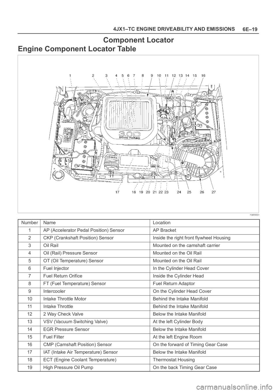
Component Locator
Engine Component Locator Table
F06RW051
NumberNameLocation
1AP (Accelerator Pedal Position) SensorAP Bracket
2CKP (Crankshaft Position) SensorInside the right front flywheel Housing
3Oil RailMounted on the camshaft carrier
4Oil (Rail) Pressure SensorMounted on the Oil Rail
5OT (Oil Temperature) SensorMounted on the Oil Rail
6Fuel InjectorIn the Cylinder Head Cover
7Fuel Return OrificeInside the Cylinder Head
8FT (Fuel Temperature) SensorFuel Return Adaptor
9IntercoolerOn the Cylinder Head Cover
10Intake Throttle MotorBehind the Intake Manifold
11Intake ThrottleBehind the Intake Manifold
122 Way Check ValveBelow the Intake Manifold
13VSV (Vacuum Switching Valve)At the left Cylinder Body
14EGR Pressure SensorBelow the Intake Manifold
15Fuel FilterAt the left Engine Room
16CMP (Camshaft Position) SensorOn the forward of Timing Gear Case
17IAT (Intake Air Temperature) SensorBelow the Intake Manifold
18ECT (Engine Coolant Temperature)Thermostat Housing
19High Pressure Oil PumpOn the back Timing Gear Case
Page 5452 of 6000
6E–23 4JX1–TC ENGINE DRIVEABILITY AND EMISSIONS
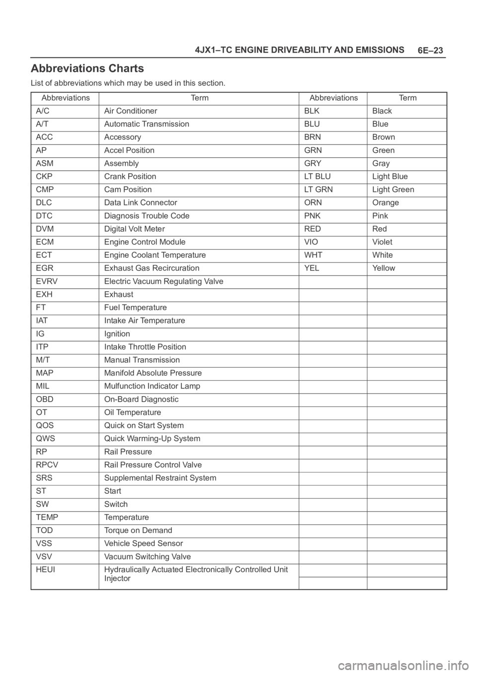
Abbreviations Charts
List of abbreviations which may be used in this section.
Abbreviations
Te r mAbbreviationsTe r m
A/CAir ConditionerBLKBlack
A/TAutomatic TransmissionBLUBlue
ACCAccessoryBRNBrown
APAccel PositionGRNGreen
ASMAssemblyGRYGray
CKPCrank PositionLT B L ULight Blue
CMPCam PositionLT G R NLight Green
DLCData Link ConnectorORNOrange
DTCDiagnosis Trouble CodePNKPink
DVMDigital Volt MeterREDRed
ECMEngine Control ModuleVIOViolet
ECTEngine Coolant TemperatureWHTWhite
EGRExhaust Gas RecircurationYELYe l l o w
EVRVElectric Vacuum Regulating Valve
EXHExhaust
FTFuel Temperature
IATIntake Air Temperature
IGIgnition
ITPIntake Throttle Position
M/TManual Transmission
MAPManifold Absolute Pressure
MILMulfunction Indicator Lamp
OBDOn-Board Diagnostic
OTOil Temperature
QOSQuick on Start System
QWSQuick Warming-Up System
RPRail Pressure
RPCVRail Pressure Control Valve
SRSSupplemental Restraint System
STStart
SWSwitch
TEMPTemperature
TODTorque on Demand
VSSVehicle Speed Sensor
VSVVacuum Switching Valve
HEUIHydraulically Actuated Electronically Controlled Unit
InjectorInjector
Page 5454 of 6000
6E–25 4JX1–TC ENGINE DRIVEABILITY AND EMISSIONS
General Service Information
Serviceability Issues
Non-OEM Parts
All of the OBD diagnostics have been calibrated to run
with OEM parts. Accordingly, if commercially sold sensor
or switch is installed, it makes a wrong diagnosis and turn
on the MIL (“Check Engine” lamp).
Aftermarket electronics, such as cellular phones,
stereos, and anti-theft devices, may radiate EMI into the
control system if they are improperly installed. This may
cause a false sensor reading and turn on the MIL (“Check
Engine” lamp).
Poor Vehicle Maintenance
The sensitivity of OBD diagnostics will cause the MIL
(“Check Engine” lamp) to turn on if the vehicle is not
maintained properly. Restricted oil filters, fuel filters, and
crankcase deposits due to lack of oil changes or improper
oil viscosity can trigger actual vehicle faults that were not
previously monitored prior to OBD. Poor vehicle
maintenance can not be classified as a “non-vehicle
fault”, but with the sensitivity of OBD diagnostics, vehicle
maintenance schedules must be more closely followed.
Related System Faults
Many of the OBD system diagnostics will not run if the
ECM detects a fault on a related system or component.
Visual/Physical Engine Compartment
Inspection
Perform a careful visual and physical engine
compartment inspection when performing any diagnostic
procedure or diagnosing the cause of an emission test
failure. This can often lead to repairing a problem without
further steps. Use the following guidelines when
performing a visual/physical inspection:
Inspect all vacuum hoses for punches, cuts,
disconnects, and correct routing.
Inspect hoses that are difficult to see behind other
components.
Inspect all wires in the engine compartment for proper
connections, burned or chafed spots, pinched wires,
contact with sharp edges or contact with hot exhaust
manifolds or pipes.
Basic Knowledge of Tools Required
NOTE: Lack of basic knowledge of this powertrain when
performing diagnostic procedures could result in an
incorrect diagnosis or damage to powertrain
components. Do not attempt to diagnose a powertrain
problem without this basic knowledge.
A basic understanding of hand tools is necessary to effec-
tively use this section of the Service Manual.
Serial Data Communications
Class II Serial Data Communications
This vehicle utilizes the “Class II” communication system.
Each bit of information can have one of two lengths: longor short. This allows vehicle wiring to be reduced by
transmitting and receiving multiple signals over a single
wire. The messages carried on Class II data streams are
also prioritized. If two messages attempt to establish
communications on the data line at the same time, only
the message with higher priority will continue. The device
with the lower priority message must wait.
On this vehicle the Tech 2 displays the actual values for
vehicle parameters. It will not be necessary to perform
any conversions from coded values to actual values.
On-Board Diagnostic (OBD)
On-Board Diagnostic Tests
A diagnostic test is a series of steps, the result of which is
a pass or fail reported to the diagnostic executive. When
a diagnostic test reports a pass result, the diagnostic
executive records the following data:
The diagnostic test has been completed since the last
ignition cycle.
The diagnostic test has passed during the current
ignition cycle.
The fault identified by the diagnostic test is not
currently active.
When a diagnostic test reports a fail result, the diagnostic
executive records the following data:
The diagnostic test has been completed since the last
ignition cycle.
The fault identified by the diagnostic test is currently
active.
The fault has been active during this ignition cycle.
The operating conditions at the time of the failure.
Comprehensive Component Monitor
Diagnostic Operation
Comprehensive component monitoring diagnostics are
required to operate engine properly.
Input Components:
Input components are monitored for circuit continuity and
out-of-range values. This includes rationality checking.
Rationality checking refers to indicating a fault when the
signal from a sensor does not seem reasonable. Accel
Position (AP) sensor that indicates high throttle position
at low engine loads or MAP voltage. Input components
may include, but are not limited to the following sensors:
Intake Air Temperature (IAT) Sensor
Crankshaft Position (CKP) Sensor
Intake throttle Position (ITP) Sensor
Engine Coolant Temperature (ECT) Sensor
Camshaft Position (CMP) Sensor
Manifold absolute Pressure (MAP) Sensor
Accel Position Sensor
Fuel Temp Sensor
Rail Pressure Sensor
Oil Temp Sensor
EGR Pressure Sensor
Vehicle Speed Sensor
Page 5456 of 6000
6E–27 4JX1–TC ENGINE DRIVEABILITY AND EMISSIONS
Non-Emissions related
Dose not request illumination of any lamp
Stores a History DTC on the first trip with a fail
Stores Fail Record when test fails
Updates the Fail Record each time the diagnostic test
fails
Storing and Erasing Freeze Frame Data and Failure
Records
The data captured is called Freeze Frame data. The
Freeze Frame data is very similar to a single record of
operating conditions. Whenever the MIL is illuminated,
the corresponding record of operating conditions is
recorded to the Freeze Frame buffer.
Data from these faults take precedence over data
associated with any other fault. The Freeze Frame data
will not be erased unless the associated history DTC is
cleared.
Each time a diagnostic test reports a failure, the current
engine operating conditions are recorded in the
Failure
Records
buffer. A subsequent failure will update the
recorded operating conditions. The following operating
conditions for the diagnostic test which failed
typically
include the following parameters:
Engine Speed
Engine Load
Engine Coolant Temperature
Vehicle Speed
Intake Throttle Position
MAP
Injector Base Pulse Width
Loop Status
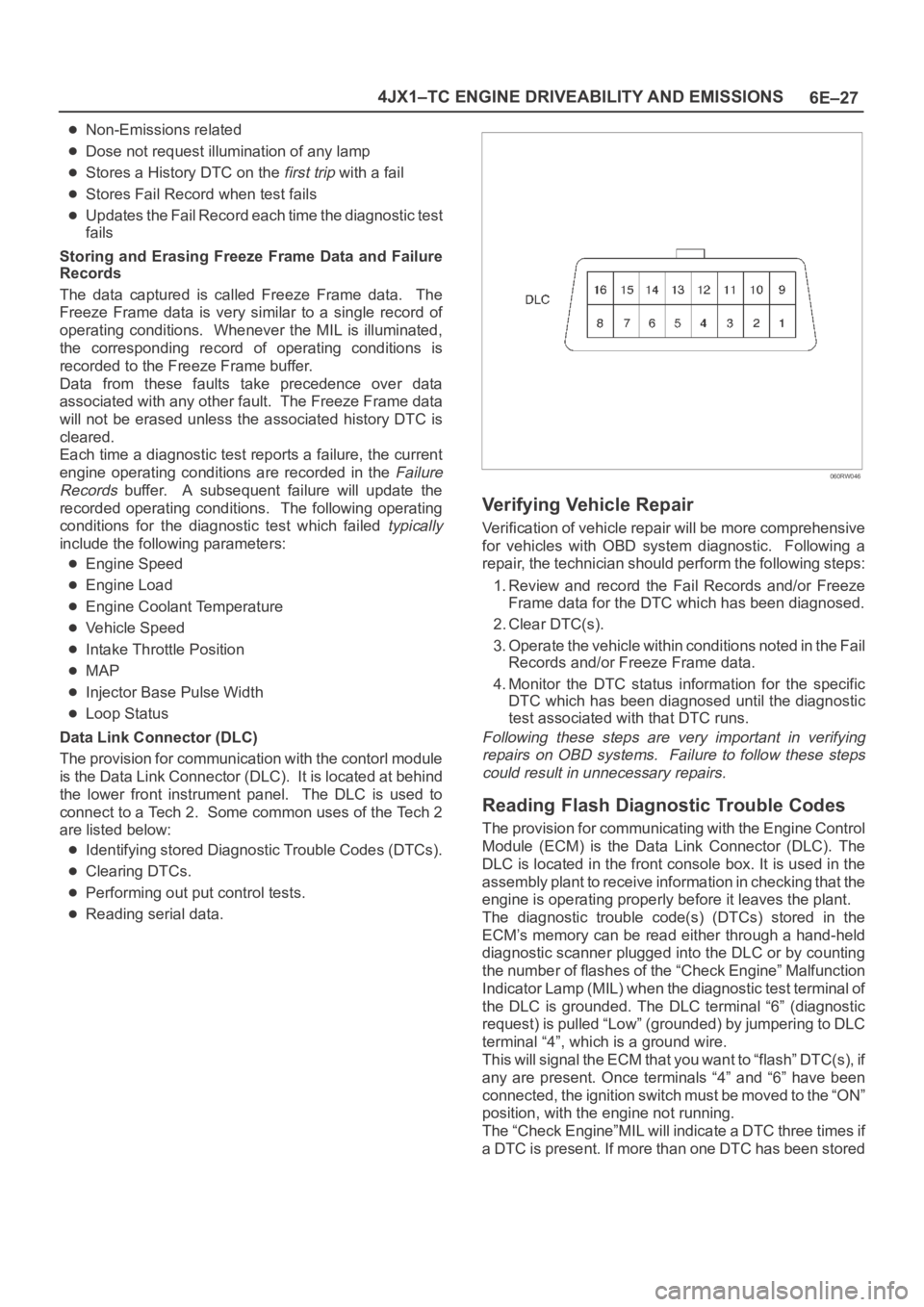
Data Link Connector (DLC)
The provision for communication with the contorl module
is the Data Link Connector (DLC). It is located at behind
the lower front instrument panel. The DLC is used to
connect to a Tech 2. Some common uses of the Tech 2
are listed below:
Identifying stored Diagnostic Trouble Codes (DTCs).
Clearing DTCs.
Performing out put control tests.
Reading serial data.
060RW046
Verifying Vehicle Repair
Verification of vehicle repair will be more comprehensive
for vehicles with OBD system diagnostic. Following a
repair, the technician should perform the following steps:
1. Review and record the Fail Records and/or Freeze
Frame data for the DTC which has been diagnosed.
2. Clear DTC(s).
3. Operate the vehicle within conditions noted in the Fail
Records and/or Freeze Frame data.
4. Monitor the DTC status information for the specific
DTC which has been diagnosed until the diagnostic
test associated with that DTC runs.
Following these steps are very important in verifying
repairs on OBD systems. Failure to follow these steps
could result in unnecessary repairs.
Reading Flash Diagnostic Trouble Codes
The provision for communicating with the Engine Control
Module (ECM) is the Data Link Connector (DLC). The
DLC is located in the front console box. It is used in the
assembly plant to receive information in checking that the
engine is operating properly before it leaves the plant.
The diagnostic trouble code(s) (DTCs) stored in the
ECM’s memory can be read either through a hand-held
diagnostic scanner plugged into the DLC or by counting
the number of flashes of the “Check Engine” Malfunction
Indicator Lamp (MIL) when the diagnostic test terminal of
the DLC is grounded. The DLC terminal “6” (diagnostic
request) is pulled “Low” (grounded) by jumpering to DLC
terminal “4”, which is a ground wire.
This will signal the ECM that you want to “flash” DTC(s), if
any are present. Once terminals “4” and “6” have been
connected, the ignition switch must be moved to the “ON”
position, with the engine not running.
The “Check Engine”MIL will indicate a DTC three times if
a DTC is present. If more than one DTC has been stored
Page 5463 of 6000
6E–34
4JX1–TC ENGINE DRIVEABILITY AND EMISSIONS
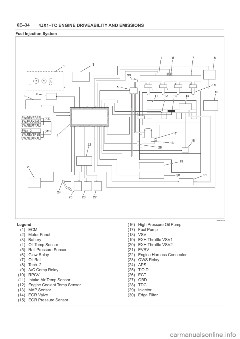
Fuel Injection System
060RW178
Legend
(1) ECM
(2) Meter Panel
(3) Battery
(4) Oil Temp Sensor
(5) Rail Pressure Sensor
(6) Glow Relay
(7) Oil Rail
(8) Tech–2
(9) A/C Comp Relay
(10) RPCV
(11) Intake Air Temp Sensor
(12) Engine Coolant Temp Sensor
(13) MAP Sensor
(14) EGR Valve
(15) EGR Pressure Sensor(16) High Pressure Oil Pump
(17) Fuel Pump
(18) VSV
(19) EXH Throttle VSV1
(20) EXH Throttle VSV2
(21) EVRV
(22) Engine Harness Connector
(23) QWS Relay
(24) APS
(25) T.O.D
(26) ECT
(27) OBD
(28) TDC
(29) Injector
(30) Edge Filter
Page 5468 of 6000
6E–39 4JX1–TC ENGINE DRIVEABILITY AND EMISSIONS
Engine Control Module ECM
Diagnosis
To read and clear diagnostic trouble codes, use a Tech 2.
IMPORTANT:Use of a Tech 2 is recommended to clear
diagnostic trouble codes from the ECM memory.
Diagnostic trouble codes can also be cleared by turning
the ignition “OFF” and disconnecting the battery power
from the ECM for 30 seconds. Turning off the ignition and
disconnecting the battery power from the ECM will cause
all diagnostic information in the ECM memory to be
cleared. Therefore, all the diagnostic tests will have to be
re-run.
Since the ECM can have a failure which may affect only
one circuit, following the diagnostic procedures in this
section will determine which circuit has a problem and
where it is.
If a diagnostic chart indicates that the ECM connections
or the ECM is the cause of a problem, and the ECM is
replaced, but this does not correct the problem, one of the
following may be the reason:
There is a problem with the ECM terminal
connections. The terminals may have to be removed
from the connector in order to check them properly.
The problem is intermittent. This means that the
problem is not present at the time the system is being
checked. In this case, refer to the
Symptoms portion
of the manual and make a careful physical inspection
of all components and wiring associated with the
affected system.
There is a shorted solenoid, relay coil, or harness.
Solenoids and relays are turned “ON” and “OFF” by
the ECM using internal electronic switches called
drivers. A shorted solenoid, relay coil, or harness will
not damage the ECM but will cause the solenoid or
relay to be inoperative.
Multiple ECM Information Sensor
DTCS Set
Circuit Description
The Engine Control Module ECM monitors various
sensors to determine the engine operating conditions.
The ECM controls fuel delivery, spark advance,
transmission operation, and emission control device
operation based on the sensor inputs.
The ECM provides a sensor ground to all of the sensors.
The ECM applies 5 volts through a pull-up resistor, and
determines the status of the following sensors by
monitoring the voltage present between the 5-volt supply
and the resistor:
The fuel temperature (FT) sensor
The engine coolant temperature (ECT) sensor
The Intake air temperature (IAT) sensor
The ECM provides the following sensors with a 5-volt
reference and a sensor ground signal:
The Intake throttle position sensor
The manifold absolute pressure sensor
The rail pressure sensor
The accelerator position sensor
The oil temperature sensor
The camshaft position sensor
The crankshaft position sensor
The EGR pressure sensor
The ECM monitors the signals from these sensors in
order to determine their operating status.
Diagnostic Aids
IMPORTANT:Be sure to inspect ECM and engine
grounds for being secure and clean.
A short to voltage in one of the sensor input circuits may
cause one or more of the following DTCs to be set:
P0337
P0342
P1193
P1404
P1405
P1488
IMPORTANT:If a sensor input circuit has been shorted
to voltage, ensure that the sensor is not damaged. A
damaged sensor will continue to indicate a high or low
voltage after the affected circuit has been repaired. If the
sensor has been damaged, replace it.
An open in the sensor ground circuit between the ECM
and the splice will cause one or more of the following
DTCs to be set:
P0337
P0342
P0117
A short to ground in the 5-volt reference A or B circuit will
cause one or more of the following DTCs to be set:
P0112
P0117
P0182
P0197
An open in the 5-volt reference circuit A, between the
ECM and the splice will cause one or more of the following
DTCs to be set:
P0107
P0405
P1194
P0122
An open in the 5-volt reference circuit B, between the
ECM and the splice will cause one or more of the following
DTCs to be set:
P1485
Check for the following conditions:
Poor connection at ECM. Inspect the harness
connectors for backed-out terminals, improper
mating, broken locks, improperly formed or damage
terminals, and a poor terminal-to-wire connection.
Damaged harness. Inspect the wiring harness for
damage. If the harness is not damaged, observe an
affected sensor’s displayed value on the Tech 2 with
the ignition “ON” and the engine “OFF” while you
move the connectors and the wiring harnesses
related to the following sensors:
ECT Sensor
Page 5470 of 6000

6E–41 4JX1–TC ENGINE DRIVEABILITY AND EMISSIONS
EGR (Exhaust Gas Recirculation)
Diagnosis
A diagnosis of the EGR system is covered by DTC
P1403.
EGR VSV circuit diagnosis is covered by DTC P1404.
EGR pressure sensor diagnosis is covered by DTC
P405 and/or P406.
EGR EVRV circuit diagnosis is covered by DTC
P1405. Refer to the DTC charts.
Tech 2 Data Definitions and Ranges
A/C CLUTCH–Tech 2 Displays ON or OFF–
Indicates whether the A/C has commanded the A/C
clutch ON.
MAP kPa — Tech 2 Range 10-105 kPa/0.00-5.00
Vo l t s —
The manifold absolute pressure reading is determined
from the MAP sensor signal monitored during key up and
wide open throttle (WOT) conditions. The manifold
absolute pressure is used to compensate for altitude
differences and is normally displayed around “61-104”
depending on altitude and manifold absolute pressure.
CMP ACT. COUNTER –Cam Position
DESIRED IDLE — Tech 2 Range 0-3187 RPM —
The idle speed that the ECM is commanding. The ECM
will compensate for various engine loads based on engine
coolant temperature, to keep the engine at the desired
speed.
ECT — (Engine Coolant Temperature) Tech 2
Range –40
C to 151C (–40F to 304F) —
The engine coolant temperature (ECT) is mounted in the
coolant stream and sends engine temperature
information to the ECM. The ECM applies 5 volts to the
ECT sensor circuit. The sensor is a thermistor which
changes internal resistance as temperature changes.
When the sensor is cold (high resistance), the ECM
monitors a high signal voltage and interprets that as a cold
engine. As the sensor warms (decreasing resistance),
the voltage signal will decrease and the ECM will interpret
the lower voltage as a warm engine.
ENGINE RUN TIME — Tech 2 Range
00:00:00-99:99:99 Hrs:Min:Sec —
Indicates the time elapsed since the engine was started.
If the engine is stopped, engine run time will be reset to
00:00:00.
ENGINE SPEED — Range 0-9999 RPM —
Engine speed is computed by the ECM from the 57X
reference input. It should remain close to desired idle
under various engine loads with engine idling.Air Intake Valve meter POSITION — Tech 2 Range
0-100 % —
IAT (INTAKE AIR TEMPERATURE)— Tech 2 Range
–40
C to 151C (–40F to 304F) —
The ECM converts the resistance of the intake air
temperature sensor to degrees. Intake air temperature
(IAT) is used by the ECM to adjust fuel delivery and spark
timing according to incoming air density.
MAP — Tech 2 Range 10-105 kPa (0.00-4.97 Volts)—
The manifold absolute pressure (MAP) sensor measures
the change in the boost pressure.
MIL — Tech 2 Displays ON or OFF —
Indicates the ECM commanded state of the malfunction
indicator lamp.
AP — Tech 2 Range 0%-100% —
AP (Accelerator position) angle is computed by the ECM
from the AP sensor voltage. AP angle should display
“0%” at idle and “100%” at wide open throttle.
AP SENSOR — Tech 2 Range 0.00-5.00 Volts —
The voltage being monitored by the ECM on the AP
sensor signal circuit.
VEHICLE SPEED—Tech 2 Range 0-255 km/h (0-155
mph)–
The vehicle speed sensor signal is converted into km/h
and mph for display.
Typical Scan Data Values
Use the Typical Scan Data Values Table only after the
On-Board Diagnostic System Check has been
completed, no DTC(s) were noted, and you have
determined that the on-board diagnostics are functioning
properly. Tech 2 values from a properly-running engine
may be used for comparison with the engine you are
diagnosing. The typical scan data values represent
values that would be seen on a normally-running engine.
NOTE: A Tech 2 that displays faulty data should not be
used, and the problem should be reported to the Tech 2
manufacturer. Use of a faulty Tech 2 can result in
misdiagnosis and unnecessary replacement of parts.
Only the parameters listed below are referred to in this
service manual for use in diagnosis. For further
information on using the Tech 2 to diagnose the ECM and
related sensors, refer to the applicable reference section
listed below. If all values are within the typical range
described below, refer to the
Symptoms section for
diagnosis.
Test Conditions
Engine running, lower radiator hose hot, transmission in
park or neutral, accessaries off, brake not applied and air
conditioning off.
Page 5472 of 6000

6E–43 4JX1–TC ENGINE DRIVEABILITY AND EMISSIONS
Te c h 2
ParameterData ListUnits
DisplayedTy p i c a l D a t a
Values (IDLE)Typical Data
Va l u e s
(2500 RPM)Refer To
Exhaust VSV1EngineOn/OffOffOffDTC P0475
Exhaust VSV2EngineOn/OffOffOffDTC P1475
Decelevation
Fuel Cut OffEngineInactive/
Active——General Description
Glow Time
LampEngineOn/OffOffOffDTC P0381
Glow Time
RelayEngineOn/OffOffOffDTC P0380
Diagnostic
RequestEngineInactive
12V/
Active 0V——General Description
A/C ClutchEngineOn/OffOffOffGeneral Description
Desired IdleEngineRPM720—General Description
ECT (Engine
Coolant Temp)EngineC (F)80 9080 90General Description
ECT
Engine SpeedEngineRPM7202500DTC P0219
MAT (Intake Air
Te m p )EngineC (F)65 8065 80DTC P0112, P0113
MAP KPa
(Manifold
Absolute
Pressure)EngineKilopascals——General Description
DTC P0107, P0108
MILEngineOn/OffOffOffGeneral Description
AP (Accel
Position)EnginePercent08 14DTC P0121, P0122,
P0123
AP (Accel
Position)EngineVo l t s0.25 0.450.8 1.0DTC P0121, P0122,
P0123
Rail Oil
TemperatureEngineC (F)——DTC P0197, P0198
Desired Throttle
Motor PositionEngineSteps———
Learned Idle
Fuel QuantityEnginemm 3/st———
Page 5478 of 6000

6E–49 4JX1–TC ENGINE DRIVEABILITY AND EMISSIONS
Engine Cranks But Will Not Run
Circuit Description
In this type of injector system, the Engine Control Module
(ECM) triggers the correct driver inside the injector, which
then triggers the correct injector based on the 57X signal
received from the crankshaft position sensor (CKP).
During crank, the ECM monitors the CKP 57X signal. The
CKP signal is used to determine which cylinder will fire
first. After the CKP 57X signal has been processed by the
ECM, it will command all four injectors to allow a priming
shot of fuel for all the cylinders. After the priming, the
injectors are left “OFF” during the next four 57X reference
pulses from the CKP. This allows each cylinder a chance
to use the fuel from the priming shot. During this waiting
period, a camshaft position (CMP) signal pulse will have
been received by the ECM. The CMP signal allows the
ECM to operate the injectors sequentially based on
camshaft position. If the camshaft position signal is not
present at start-up, the ECM will begin sequential fuel
delivery with a 1-in-4 chance that fuel delivery is correct.
The engine will run without a CMP signal, but will set a
DTC code.
Diagnostic Aids
An intermittent problem may be caused by a poor
connection, rubbed-through wire insulation or a wirebroken inside the insulation. Check for the following
items:
Poor connection or damaged harness – Inspect the
ECM harness and connectors for improper mating,
broken locks, improperly formed or damaged
terminals, poor terminal-to-wore connection, and
damaged harness.
Faulty engine coolant temperature sensor – Using a
Tech 2, compare engine coolant temperature with
manifold air temperature on a completely cool engine.
Test Description
Number(s) below refer to the step number(s) on the
Diagnostic Chart.
4. An obvious cause of low fuel pressure would be an
empty fuel tank.
5. The engine will easily start and run if a few injectors
are disabled. It is not necessary to test all injectors
at this time since this step is only a test to verify that
all of the injectors have not been disabled by fuel
contamination.
8.If there is an open or shorted driver circuit, DTCs
0201-0204 should be set.
Engine Cranks But Will Not Run
StepActionVa l u e ( s )Ye sNo
1Was the “On-Board Diagnostic (OBD) System Check”
performed?
—Go to Step 2
Go to OBD
System
Check
2Check the 15 A injector fuse, the 15 A engine device
fuse, and the 15A ECM fuse.
Was a fuse blown?
—Go to Step 3Go to Step 4
3Check for a short to ground and replace the fuse.
Is the action complete?
—Verify repair—
4Is fuel tank empty?
—
Fill the fuel
tank
Go to Step 5
5Is the right fuel using?
—Go to Step 6
Replace the
fuel
6Is the right engine oil using?
—Go to Step 7
Replace the
engine oil
7Using the Tech–2.
Is DTC P0192 or P0193 set? (Check rail pressure
system)
—
Go to DTC
P0192 or
DTC P0193
Go to Step 8
8Using the Tech–2.
Is DTC P0201 – P0204 set? (Check inject circuit fault)
—
Go to DTC
P0201 –
P0204
Go to Step 9
9Using the Tech–2.
Is DTC P1657 set? (Check ECM Main relay)
—
Go to DTC
P1657
Go to Step 10
Page 5483 of 6000

6E–54
4JX1–TC ENGINE DRIVEABILITY AND EMISSIONS
ECM Diagnostic Trouble Codes
The following table lists the diagnostic trouble codes
supported a Tech 2 and to flash.If any DTCs not listedhere are displayed by a Tech 2, the Tech 2 data may be
faulty; notify the Tech 2 manufacturer of any DTCs
displayed that are not included in the following table.
ECM Diagnostic Trouble Codes
DTC
using a
Te c h 2
Flash DTCDescriptionMIL
P010734MAP Sensor Low VoltageON
P010834MAP Sensor High VoltageON
P011223Intake Air temp Sensor Low VoltageON
P011323Intake Air temp Sensor High VoltageON
P011714Engine Coolant Temp Sensor Low VoltageON
P011814Engine Coolant Temp Sensor High VoltageON
P012133Accel Position Sensor RationalityON
P012221Accel Position Sensor Low VoltageON
P012321Accel Position Sensor High VoltageON
P018215Fuel Temp Sensor Low VoltageON
P018315Fuel Temp Sensor High VoltageON
P019263Rail Pressure Sensor Low VoltageON
P019363Rail Pressure Sensor High VoltageON
P119364RPCV Circuit Open/Short—
P119461Rail Pressure System Low VoltageON
P119561Rail Pressure System High VoltageON
P119662Rail Pressure System High WarningON
P019716Oil Temp sensor Low VoltageON
P019816Oil Temp sensor High VoltageON
P020151Injector #1 Circuit FaultON
P020252Injector #2 Circuit FaultON
P020353Injector #3 Circuit FaultON
P020454Injector #4 Circuit FaultON
P021722High Coolant Temp WarningON
P121736High Oil Temp WarningON
P021911Engine Over Speed WarningON
P033643Crank Position Sensor Out of SyncroON
P033743Crank Position Sensor No SignalON
P034141Cam Position Sensor Out of SyncroON
P034241Cam Position Sensor No SignalON
P038066Glow Relay Circuit Open/Short—
P038167Glow Lamp Circuit Open/Short—
P140332EGR EVRV Fault—
P140431EGR VSV Circuit—
P040526EGR Pressure Sensor Low VoltageON
P140537EGR EVRV Circuit Open/Short—
P040626EGR Pressure Sensor High VoltageON