weight OPEL FRONTERA 1998 Owner's Manual
[x] Cancel search | Manufacturer: OPEL, Model Year: 1998, Model line: FRONTERA, Model: OPEL FRONTERA 1998Pages: 6000, PDF Size: 97 MB
Page 4999 of 6000

6E–342
ENGINE DRIVEABILITY AND EMISSIONS
PCM to calculate true sequential multiport fuel injection
(SFI). Loss of this signal will set a DTC P0341. If the CMP
signal is lost while the engine is running, the fuel injection
system will shift to a calculated sequential fuel injection
based on the last fuel injection pulse, and the engine will
continue to run. The engine can be restarted and will run
in the calculated sequential mode as long as the fault is
present, with a 1-in-6 chance of being correct.
Clear Flood Mode
Clear a flooded engine by pushing the accelerator pedal
down all the way. The PCM then de-energizes the fuel
injectors. The PCM holds the fuel injectors de-energized
as long as the throttle remains above 80% and the engine
speed is below 800 RPM. If the throttle position becomes
less than 80%, the PCM again begins to pulse the
injectors “ON” and “OFF,” allowing fuel into the cylinders.
Deceleration Mode
The PCM reduces the amount of fuel injected when it
detects a decrease in the throttle position and the air flow.
When deceleration is very fast, the PCM may cut off fuel
completely for short periods.
Engine Speed/Vehicle Speed/Fuel Disable
Mode
The PCM monitors engine speed. It turns off the fuel
injectors when the engine speed increase above 6400
RPM. The fuel injectors are turned back on when engine
speed decreases below 6150 RPM.
Fuel Cutoff Mode
No fuel is delivered by the fuel injectors when the ignition
is “OFF.” This prevents engine run-on. In addition, the
PCM suspends fuel delivery if no reference pulses are
detected (engine not running) to prevent engine flooding.
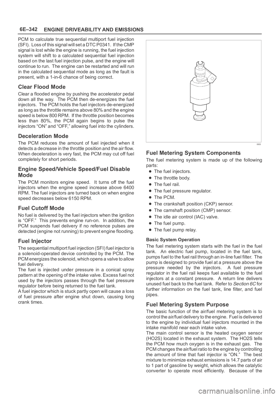
Fuel Injector
The sequential multiport fuel injection (SFI) fuel injector is
a solenoid-operated device controlled by the PCM. The
PCM energizes the solenoid, which opens a valve to allow
fuel delivery.
The fuel is injected under pressure in a conical spray
pattern at the opening of the intake valve. Excess fuel not
used by the injectors passes through the fuel pressure
regulator before being returned to the fuel tank.
A fuel injector which is stuck partly open will cause a loss
of fuel pressure after engine shut down, causing long
crank times.
0003
Fuel Metering System Components
The fuel metering system is made up of the following
parts:
The fuel injectors.
The throttle body.
The fuel rail.
The fuel pressure regulator.
The PCM.
The crankshaft position (CKP) sensor.
The camshaft position (CMP) sensor.
The idle air control (IAC) valve.
The fuel pump.
The fuel pump relay.
Basic System Operation
The fuel metering system starts with the fuel in the fuel
tank. An electric fuel pump, located in the fuel tank,
pumps fuel to the fuel rail through an in-line fuel filter. The
pump is designed to provide fuel at a pressure above the
pressure needed by the injectors. A fuel pressure
regulator in the fuel rail keeps fuel available to the fuel
injectors at a constant pressure. A return line delivers
unused fuel back to the fuel tank. Refer to
Section 6C f o r
further information on the fuel tank, line filter, and fuel
pipes.
Fuel Metering System Purpose
The basic function of the air/fuel metering system is to
control the air/fuel delivery to the engine. Fuel is delivered
to the engine by individual fuel injectors mounted in the
intake manifold near each intake valve.
The main control sensor is the heated oxygen sensor
(HO2S) located in the exhaust system. The HO2S tells
the PCM how much oxygen is in the exhaust gas. The
PCM changes the air/fuel ratio to the engine by controlling
the amount of time that fuel injector is “ON.” The best
mixture to minimize exhaust emissions is 14.7 parts of air
to 1 part of gasoline by weight, which allows the catalytic
converter to operate most efficiently. Because of the
Page 5276 of 6000

ENGINE MECHANICAL 6A – 3
SERVICE INFORMATION
MAIN DATA AND SPECIFICATION
Engine type Diesel, four cycle water cooled inline
Camshaft type DOHC
Number of cylinders 4
Bore x stroke (mm) 95.4 x 104.9
Total piston displacement (cc) 2999
Compression ratio (to 1) 19.0
Engine weight (dry) N (kg/lb) 2492 (254/560) (A/T)
2649 (270/593) (M/T)
Engine idling speed (Reference) RPM 720
Compression pressure kpa (kg/cm
2/psi)-rpm 3000 (31/440)-200
Firing order 1–3–4–2
VALVE SYSTEM
Intake valves open at: B.T.D.C. 3°
close at: A.B.D.C. 57.6°
Exhaust valves open at: B.B.D.C. 56.5°
close at: A.T.D.C. 5°
Valve clearance at cold mm (in)
intake: 0.15 (0.006)
exhaust: 0.25 (0.01)
Oil filter Full flow and bypass combined type
Oil capacity (Original factory fill or rebuilt engine) 9.0 liters (7.9 US quarts)
Oil capacity (Service change)
with filter change 6.0 liters (6.3 US quarts)
without filter change 5.0 liters (5.3 US quarts)
Oil cooler Water cooled type
Inter cooler Air cooled type
Turbocharger method
Control method Wastegate control
Lubrication Pressurized control
Cooling method Coolant cooled
Page 5277 of 6000

6A – 4 ENGINE MECHANICAL
Engine Cooling
Starting System
Cooling system Coolant forced circulation
Radiator (2 tube in row) Tube type corrugated
Heat radiation capacity J/h (kcal/h) 318 x 10
6(76000)
Heat radiation area m
2(ft2) 15.63 (1.454)
Front area m
2(ft2) 0.309 (2.029)
Dry weight N (kg/lb) 83 (8.5/18.7)
Radiator cap
Valve opening pressure kPa (kg/cm
2psi) 93.3 – 122.7 (0.95 – 1.25/13.5 – 17.8)
Coolant capacity lit (Imp.qt./US qt.) M/T 2.5 (2.2/2.6) A/T 2.4 (2.1/2.5)
Coolant pump Centrifugal impeller type
Pulley ratio 1.2
Coolant total capacity lit (Imp.qt./US qt.) 9.3 (8.2/9.8)
Model HITACHI S14-0
Rating
Voltage V 12
Output kW 2.8
Time sec 30
Number of teeth of pinion 9
Rotating direction (as viewed from pinion) Clockwise
Weight (approx.) N(kg/lb) 49 (5.0/11)
No-load characteristics
Voltage/current V/A 11/160 or less
Speed rpm 4000 or more
Load characteristics
Voltage/current V/A 8.76/300
Torque Nꞏm(kgꞏm/lbꞏft) 7.4 (0.75/5.4) or more
Speed rpm 1700 or more
Locking characteristics
Voltage/current V/A 2.5/1100 or less
Torque Nꞏm(kgꞏm/lbꞏft) 18.6 (1.9/14) or more
Page 5278 of 6000

ENGINE MECHANICAL 6A – 5
Charging System
Model (HITACHI) LR160-734B LR170 – 760 LR190 – 750B
Rated voltage V 12
Rated output A 60 70 90
Rotation direction
Clockwise
(As viewed from pulled)
Pulley effective diameter mm (in) 60 (2.36) 69 (2.72)
Weight N (kg/lb) 41 (4.2/9.3) 52 (5.3/11.7)
Page 5358 of 6000

ENGINE MECHANICAL 6A – 85
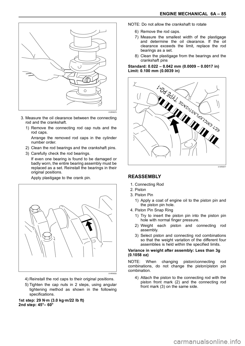
3. Measure the oil clearance between the connecting
rod and the crankshaft.
1) Remove the connecting rod cap nuts and the
rod caps.
Arrange the removed rod caps in the cylinder
number order.
2) Clean the rod bearings and the crankshaft pins.
3) Carefully check the rod bearings.
If even one bearing is found to be damaged or
badly worn, the entire bearing assembly must be
replaced as a set. Reinstall the bearings in their
original positions.
Apply plastigage to the crank pin.
4) Reinstall the rod caps to their original positions.
5) Tighten the cap nuts in 2 steps, using angular
tightening method as shown in the following
specifications.
1st step: 29 Nꞏm (3.0 kgꞏm/22 lb ft)
2nd step: 45°– 60°NOTE: Do not allow the crankshaft to rotate
6) Remove the rod caps.
7) Measure the smallest width of the plastigage
and determine the oil clearance. If the oil
clearance exceeds the limit, replace the rod
bearings as a set.
8) Clean the plastigage from the bearings and the
crankshaft pins
Standard: 0.022 – 0.042 mm (0.0009 – 0.0017 in)
Limit: 0.100 mm (0.0039 in)
REASSEMBLY
1. Connecting Rod
2. Piston
3. Piston Pin
1) Apply a coat of engine oil to the piston pin and
the piston pin hole.
4. Piston Pin Snap Ring
1) Try to insert the piston pin into the piston pin
hole with normal finger pressure.
2) Weight each piston and connecting rod
assembly.
3) Select piston and connecting rod combinations
so that the weight variation of the different four
assemblies is held within the specified limits.
Variance in weight after assembly: Less than 3g
(0.1058 oz)
NOTE: When changing piston/connecting rod
combinations, do not change the piston/piston pin
combination.
4) Attach the piston to the connecting rod with the
piston front mark (2) and the connecting rod
front mark (3) on the same side.
014RW055
012RW075
014RW077
Page 5745 of 6000

7A–56
AUTOMATIC TRANSMISSION (4L30–E)
Ensure free rotation of pump using 5–8840–2273–0
(J–23082–01) oil pump rotation tool.
241RW010
38. Overdrive clutch end play measurement.
1. Fit 5–8840–2271–0 (J–25022) and
5–8840–0618–0 (J–24773–1) turbine shaft puller
on turbine shaft.
2. Position axial play checking tool on converter
housing mating face.
3. Pull turbine shaft upwards with puller until first
resistance is met. (due to weight of overdrive
assembly).
4. Maintain shaft in this position and set indicator to
zero.
5. Pull turbine shaft further upwards with puller.
Read end play shown on indicator.
End play: 0.1mm – 0.8mm (0.004 in – 0.031in)6. Remove axial play checking tool and puller.
NOTE: If end play is not correct, repeat selective washer
selection.
252RW010
39. Inspect extension housing oil seal and replace if
necessary, using 5–8840–2282–0 (J–36797)
extension housing oil seal installer.
Rotate transmission to horizontal position, with
valve body side down.
Inspect parking wheel seal ring. Replace if
necessary.
Install wheel parking lock assembly (35).
40. Install speed wheel (36) and snap ring (37).
NOTE: Use extra long, needle-nose pliers.
41. Install gasket onto extension assembly with a thin
coating of oil.
Install extension housing assembly (38), and align
parking pawl shaft.
Install actuator assembly into extension assembly.
Install seven 8 mm hexagon socket head screws.
To r q u e : 3 2 N
m (3.3 kgꞏm/24 lb ft)
42. Inspect speed sensor O–ring. Replace if necessary.
Install speed sensor assembly (39) and 10 mm
screw.
To r q u e : 9 N
m (0.9 kgꞏm/78 lb in)