check engine OPEL FRONTERA 1998 Workshop Manual
[x] Cancel search | Manufacturer: OPEL, Model Year: 1998, Model line: FRONTERA, Model: OPEL FRONTERA 1998Pages: 6000, PDF Size: 97 MB
Page 1461 of 6000
6E–344
ENGINE DRIVEABILITY AND EMISSIONS
0006
Run Mode
The run mode has the following two conditions:
Open loop
Closed loop
When the engine is first started the system is in “open
loop” operation. In “open loop,” the PCM ignores the
signal from the heated oxygen sensor (HO2S). It
calculates the air/fuel ratio based on inputs from the TP,
ECT, and MAF sensors.
The system remains in “open loop” until the following
conditions are met:
The HO2S has a varying voltage output showing that
it is hot enough to operate properly (this depends on
temperature).
The ECT has reached a specified temperature.
A specific amount of time has elapsed since starting
the engine.
Engine speed has been greater than a specified RPM
since start-up.
The specific values for the above conditions vary with
different engines and are stored in the programmable
read only memory (PROM). When these conditions are
met, the system enters “closed loop” operation. In
“closed loop,” the PCM calculates the air/fuel ratio
(injector on-time) based on the signal from the HO2S.
This allows the air/fuel ratio to stay very close to 14.7:1.
Starting Mode
When the ignition is first turned “ON,” the PCM energizes
the fuel pump relay for two seconds to allow the fuel pump
to build up pressure. The PCM then checks the engine
coolant temperature (ECT) sensor and the throttle
position (TP) sensor to determine the proper air/fuel ratio
for starting.
The PCM controls the amount of fuel delivered in the
starting mode by adjusting how long the fuel injectors are
energized by pulsing the injectors for very short times.
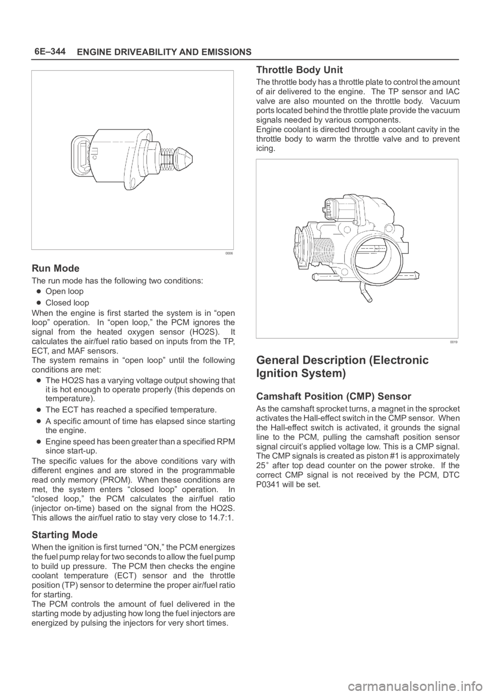
Throttle Body Unit
The throttle body has a throttle plate to control the amount
of air delivered to the engine. The TP sensor and IAC
valve are also mounted on the throttle body. Vacuum
ports located behind the throttle plate provide the vacuum
signals needed by various components.
Engine coolant is directed through a coolant cavity in the
throttle body to warm the throttle valve and to prevent
icing.
0019
General Description (Electronic
Ignition System)
Camshaft Position (CMP) Sensor
As the camshaft sprocket turns, a magnet in the sprocket
activates the Hall-effect switch in the CMP sensor. When
the Hall-effect switch is activated, it grounds the signal
line to the PCM, pulling the camshaft position sensor
signal circuit’s applied voltage low. This is a CMP signal.
The CMP signals is created as piston #1 is approximately
25
after top dead counter on the power stroke. If the
correct CMP signal is not received by the PCM, DTC
P0341 will be set.
Page 1465 of 6000
6E–348
ENGINE DRIVEABILITY AND EMISSIONS
oil to enter the cylinder, particularly if the deposits are
heavier on the side of the spark plug facing the intake
valve.
TS23995
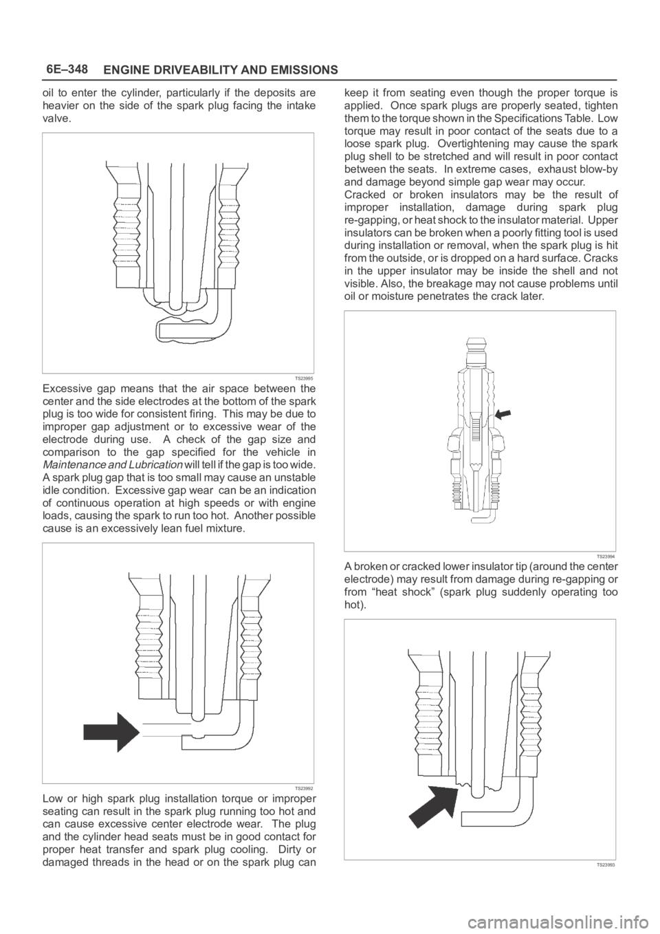
Excessive gap means that the air space between the
center and the side electrodes at the bottom of the spark
plug is too wide for consistent firing. This may be due to
improper gap adjustment or to excessive wear of the
electrode during use. A check of the gap size and
comparison to the gap specified for the vehicle in
Maintenance and Lubrication will tell if the gap is too wide.
A spark plug gap that is too small may cause an unstable
idle condition. Excessive gap wear can be an indication
of continuous operation at high speeds or with engine
loads, causing the spark to run too hot. Another possible
cause is an excessively lean fuel mixture.
TS23992
Low or high spark plug installation torque or improper
seating can result in the spark plug running too hot and
can cause excessive center electrode wear. The plug
and the cylinder head seats must be in good contact for
proper heat transfer and spark plug cooling. Dirty or
damaged threads in the head or on the spark plug cankeep it from seating even though the proper torque is
applied. Once spark plugs are properly seated, tighten
them to the torque shown in the Specifications Table. Low
torque may result in poor contact of the seats due to a
loose spark plug. Overtightening may cause the spark
plug shell to be stretched and will result in poor contact
between the seats. In extreme cases, exhaust blow-by
and damage beyond simple gap wear may occur.
Cracked or broken insulators may be the result of
improper installation, damage during spark plug
re-gapping, or heat shock to the insulator material. Upper
insulators can be broken when a poorly fitting tool is used
during installation or removal, when the spark plug is hit
from the outside, or is dropped on a hard surface. Cracks
in the upper insulator may be inside the shell and not
visible. Also, the breakage may not cause problems until
oil or moisture penetrates the crack later.
TS23994
A broken or cracked lower insulator tip (around the center
electrode) may result from damage during re-gapping or
from “heat shock” (spark plug suddenly operating too
hot).
TS23993
Page 1474 of 6000
6F–3 ENGINE EXHAUST
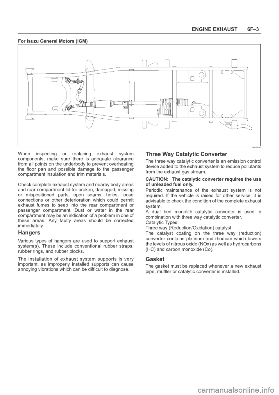
For Isuzu General Motors (IGM)
150RW058
When inspecting or replacing exhaust system
components, make sure there is adequate clearance
from all points on the underbody to prevent overheating
the floor pan and possible damage to the passenger
compartment insulation and trim materials.
Check complete exhaust system and nearby body areas
and rear compartment lid for broken, damaged, missing
or mispositioned parts, open seams, holes, loose
connections or other deterioration which could permit
exhaust fumes to seep into the rear compartment or
passenger compartment. Dust or water in the rear
compartment may be an indication of a problem in one of
these areas. Any faulty areas should be corrected
immediately.
Hangers
Various types of hangers are used to support exhaust
system(s). These include conventional rubber straps,
rubber rings, and rubber blocks.
The installation of exhaust system supports is very
important, as improperly installed supports can cause
annoying vibrations which can be difficult to diagnose.
Three Way Catalytic Converter
The three way catalytic converter is an emission control
device added to the exhaust system to reduce pollutants
from the exhaust gas stream.
CAUTION: The catalytic converter requires the use
of unleaded fuel only.
Periodic maintenance of the exhaust system is not
required. If the vehicle is raised for other service, it is
advisable to check the condition of the complete exhaust
system.
A dual bed monolith catalytic converter is used in
combination with three way catalytic converter.
Catalytic Types:
Three way (Reduction/Oxidation) catalyst
The catalyst coating on the three way (reduction)
converter contains platinum and rhodium which lowers
the levels of nitrous oxide (NOx) as well as hydrocarbons
(HC) and carbon monoxide (Co).
Gasket
The gasket must be replaced whenever a new exhaust
pipe, muffler or catalytic converter is installed.
Page 1483 of 6000
6G–4
ENGINE LUBRICATION
11. Remove drive gear.
12. Remove oil seal.
13. Remove O-ring.
Inspection and Repair
CAUTION: Make necessary correction or parts
replacement if wear, damage or any other abnormal
conditions are found during inspection.
Relief Valve (8)
Check to see that the relief valve slides freely.
The oil pump must be replaced if the relief valve does
not slide freely.
Replace the spring and/or the oil pump assembly (5) if
the spring is damaged or badly worn.
051RS002
Body (14) and Gears (10, 11)
The pump assembly must be replaced if one or more of
the conditions below is discovered during inspection.
Badly worn or damaged driven gear (10).
Badly worn drive gear (11) driving face.
Badly scratched or scored body sliding face (14) or
driven gear (10).
Badly worn or damaged gear teeth.
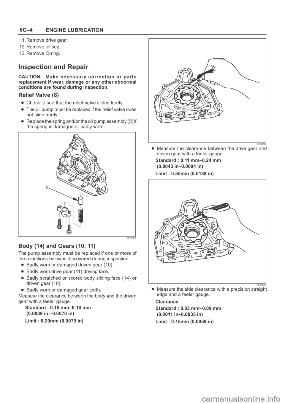
Measure the clearance between the body and the driven
gear with a feeler gauge.
Standard : 0.10 mm–0.18 mm
(0.0039 in.–0.0070 in)
Limit : 0.20mm (0.0079 in)
051RS004
Measure the clearance between the drive gear and
driven gear with a feeler gauge.
Standard : 0.11 mm–0.24 mm
(0.0043 in–0.0094 in)
Limit : 0.35mm (0.0138 in)
051RS003
Measure the side clearance with a precision straight
edge and a feeler gauge.
Clearance
Standard : 0.03 mm–0.09 mm
(0.0011 in–0.0035 in)
Limit : 0.15mm (0.0059 in)
Page 1484 of 6000
6G–5 ENGINE LUBRICATION
051RS005
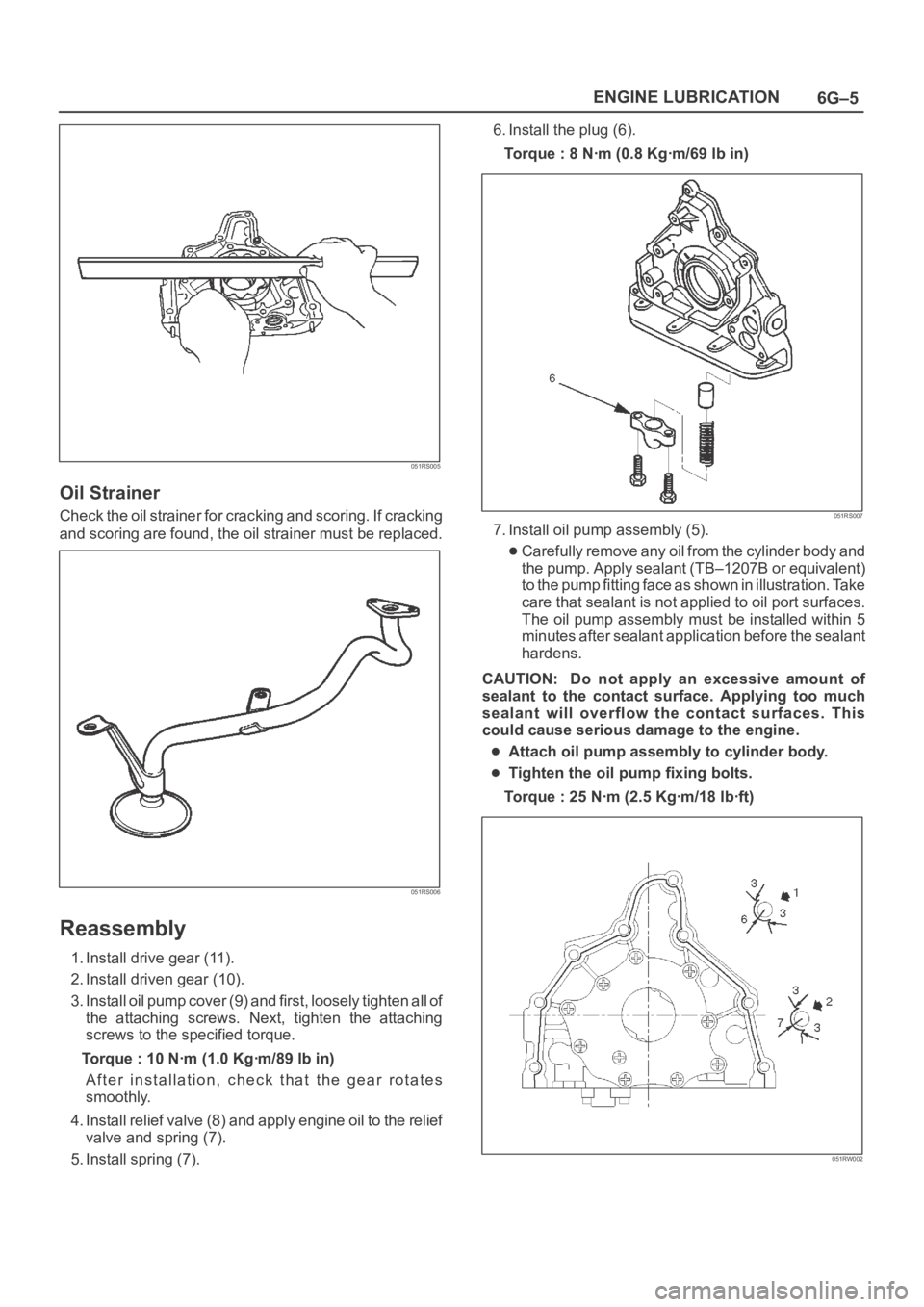
Oil Strainer
Check the oil strainer for cracking and scoring. If cracking
and scoring are found, the oil strainer must be replaced.
051RS006
Reassembly
1. Install drive gear (11).
2. Install driven gear (10).
3. Install oil pump cover (9) and first, loosely tighten all of
the attaching screws. Next, tighten the attaching
screws to the specified torque.
Torque : 10 Nꞏm (1.0 Kgꞏm/89 lb in)
After installation, check that the gear rotates
smoothly.
4. Install relief valve (8) and apply engine oil to the relief
valve and spring (7).
5. Install spring (7).6. Install the plug (6).
Torque : 8 Nꞏm (0.8 Kgꞏm/69 lb in)
051RS007
7. Install oil pump assembly (5).
Carefully remove any oil from the cylinder body and
the pump. Apply sealant (TB–1207B or equivalent)
to the pump fitting face as shown in illustration. Take
care that sealant is not applied to oil port surfaces.
The oil pump assembly must be installed within 5
minutes after sealant application before the sealant
hardens.
CAUTION: Do not apply an excessive amount of
sealant to the contact surface. Applying too much
sealant will overflow the contact surfaces. This
could cause serious damage to the engine.
Attach oil pump assembly to cylinder body.
Tighten the oil pump fixing bolts.
Torque : 25 Nꞏm (2.5 Kgꞏm/18 lbꞏft)
051RW002
Page 1496 of 6000
6H–2
ENGINE SPEED CONTROL SYSTEM
Accelerator Pedal Control Cable
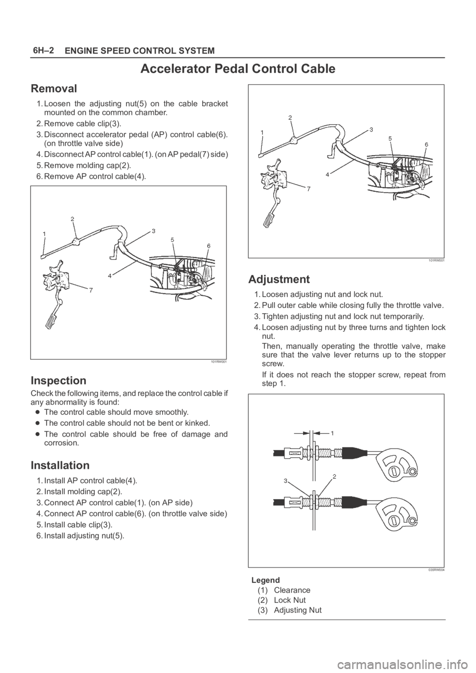
Removal
1. Loosen the adjusting nut(5) on the cable bracket
mounted on the common chamber.
2. Remove cable clip(3).
3. Disconnect accelerator pedal (AP) control cable(6).
(on throttle valve side)
4. Disconnect AP control cable(1). (on AP pedal(7) side)
5. Remove molding cap(2).
6. Remove AP control cable(4).
101RW001
Inspection
Check the following items, and replace the control cable if
any abnormality is found:
The control cable should move smoothly.
The control cable should not be bent or kinked.
The control cable should be free of damage and
corrosion.
Installation
1. Install AP control cable(4).
2. Install molding cap(2).
3. Connect AP control cable(1). (on AP side)
4. Connect AP control cable(6). (on throttle valve side)
5. Install cable clip(3).
6. Install adjusting nut(5).
101RW001
Adjustment
1. Loosen adjusting nut and lock nut.
2. Pull outer cable while closing fully the throttle valve.
3. Tighten adjusting nut and lock nut temporarily.
4. Loosen adjusting nut by three turns and tighten lock
nut.
Then, manually operating the throttle valve, make
sure that the valve lever returns up to the stopper
screw.
If it does not reach the stopper screw, repeat from
step 1.
035RW004
Legend
(1) Clearance
(2) Lock Nut
(3) Adjusting Nut
Page 1736 of 6000

ENGINE MECHANICAL 6A – 3
SERVICE INFORMATION
MAIN DATA AND SPECIFICATION
Engine type Diesel, four cycle water cooled inline
Camshaft type DOHC
Number of cylinders 4
Bore x stroke (mm) 95.4 x 104.9
Total piston displacement (cc) 2999
Compression ratio (to 1) 19.0
For Europe : 18.5
Engine weight (dry) N (kg/lb) 2492 (254/560) (A/T)
For Europe : 2422 (247/545) (A/T)
2649 (270/593) (M/T)
For Europe : 2697 (275/606) (M/T)
Engine idling speed (Reference) RPM 720
Compression pressure kpa (kg/cm
2/psi)-rpm 3040 (31/441)-200
Firing order 1–3–4–2
VALVE SYSTEM
Intake valves open at: B.T.D.C. 3°
close at: A.B.D.C. 57.6°
Exhaust valves open at: B.B.D.C. 56.5°
close at: A.T.D.C. 5°
Valve clearance (at cold) mm (in)
intake: 0.15 (0.006)
exhaust: 0.25 (0.01)
Oil filter Full flow and bypass combined type
Oil capacity (Original factory fill or rebuilt engine) 9.0 liters (7.9 US quarts)
Oil capacity (Service change)
with filter change 6.0 liters (6.3 US quarts)
without filter change 5.0 liters (5.3 US quarts)
Oil cooler Water cooled type
Inter cooler Air cooled type
Turbocharger method
Control method Wastegate control
Lubrication Pressurized control
Cooling method Coolant cooled
Crankshaft
As tufftriding (Nitrizing treatment) is applied to increase
crankshaft strength, crankpins and journals should not
be reground.
Piston Cooling
An oiling jet device for piston cooling is provided in the
lubricating oil circuit from the cylinder block oil gallery
via a check valve.
Take care not to damage any oiling jet when removing
and installing piston and connecting assembly.
Fuel Injection System
The injection system is oil rail type.
Quick On Start 4 System
QOS4 preheating system which features a quick-on
glow plug with thermometer control of the glowing time
and the afterglow time function, is applied.
Page 1743 of 6000

6A – 10 ENGINE MECHANICAL
8. Check the engine oil level and replenish to the
specified level if required.
9. Start the engine and check for oil leakage from the
main oil filter.
FUEL SYSTEM
Fuel filter
Replacement Procedure
1. Loosen the used fuel filter by turning it
counterclockwise with the filter wrench.
Filter Wrench : 5-8840-0203-0
2. Clean the filter cover fitting faces.
This will allow the new fuel filter to seat properly.
3. Apply a light coat of engine oil to the O-ring.
4. Turn the fuel filter until the sealing face comes in
contact with the O-ring.
5. Turn the fuel filter with a filter wrench 2/3 of a turn
until sealed.
Filter Wrench: 5-8840-0203-0Legend
(1) Priming pump
6. Operate the priming pump until the air is discharged
completely from fuel system.
NOTE: The use of an Isuzu genuine fuel filter is
strongly recommended.
COOLING SYSTEM
Coolant Level
Check the coolant level and replenish the radiator
reserve tank as necessary.
If the coolant level falls below the “‘MIN” line, carefully
check the cooling system for leakage. Then add
enough coolant to bring the level up to the “MAX” line.
NOTE: Do not overfill the reserve tank.
012RW112
012RW078
1
012RW111
012RW080
Page 1744 of 6000

ENGINE MECHANICAL 6A – 11
Remove the radiator filler cap only when absolutely
necessary.
Always check the coolant level when the engine is cold.
Always refer to the chart at the left to determine the
correct cooling water to antifreeze solution mixing ratio.
Cooling System Inspection
Install a radiator filler cap tester to the radiator. Apply
testing pressure to the cooling system to check for
leakage.
The testing pressure must not exceed the specified
pressure.
Testing Pressure: 196 kPa (2 kg/cm
2/28.45 psi)
Radiator Cap Inspection
The radiator filler cap is designed to maintain coolant
pressure in the cooling system at 103 kPa (1.05
kg/cm
2/15 psi).
Check the radiator filler cap with a radiator filler cap
tester.The radiator filler cap must be replaced if it fails to hold
the specified pressure during the test procedure.
Radiator Filler Cap Pressure Valve: 88.2 – 117.6 kPa
(0.899 – 1.199 kg/cm
2/12.8 – 17.1 psi)
Negative Valve (Reference): 1.0 – 3.9 kPa
(0.01 – 0.04 kg/cm
2/0.14 – 0.57 psi)
Thermostat Operating Test
1. Completely submerge the thermostat in water.
2. Heat the water.
Stir the water constantly to avoid direct heat being
applied to the thermostat.
3. Check the thermostat initial opening temperature.
Thermostat Initial Opening Temperature:
83 – 87°C (181 – 189°F)
4. Check the thermostat full opening temperature.
Thermostat Full Opening Temperature:
100°C (212°F)
Valve Lift at Fully Open Position: 9.5 mm (0.374
in)0
-10
-20
-30
-40
-50
-60
10 20 30
Mixing ratio (%)
Freezing point (
C)
40 50 60
111RW002
110RS005
110RS006
031RS003
Page 1745 of 6000

6A – 12 ENGINE MECHANICAL
Drive Belt Adjustment
Check the drive belt tension
Depress the drive belt mid-portion with a 98 N (10 kg/
22 lb) force.
Drive Belt Deflection: 10 mm (0.39 in)
Check the drive belt for cracking and other damage.
Legend
(1) Crankshaft pulley
(2) Generator pulley
(3) Cooling fan pulley
(4) A/C compressor pulley
(5) Belt tensioner pulley
Cooling Fan Pulley Drive Belt
Fan belt tension is adjusted by moving the generator.
Depress the drive belt mid-portion with a 98 N (10 kg/
22 lb) force.Legend
(1) Crankshaft pulley
(2) Generator pulley
(3) Cooling fan pulley
Compressor Pulley Drive Belt
Move the tensioner pulley as required to adjust the
compressor drive belt tension.
Depress the drive belt mid-portion with a 98 N (10 kg/
22 lb) force.
Legend
(1) Crankshaft pulley
(2) Generator pulley
(3) Cooling fan pulley
(4) A/C compressor pulley
(5) Belt tensioner pulley
5
3
24
1
012RW110
3
2
1
012RW084
5
3
24
1
012RW110