Front differential OPEL FRONTERA 1998 Owner's Guide
[x] Cancel search | Manufacturer: OPEL, Model Year: 1998, Model line: FRONTERA, Model: OPEL FRONTERA 1998Pages: 6000, PDF Size: 97 MB
Page 467 of 6000
DIFFERENTIAL (FRONT) 4A1–30
MEMO
Page 470 of 6000
DIFFERENTIAL (REAR 220mm)
4A2A–3
Diagnosis
Many noises that seem to come from the rear axle
actually originate from other sources such as tires, road
surface, wheel bearings, engine, transmission, muffler, or
body drumming. Investigate to find the source of the
noise before disassembling the rear axle. Rear axles, like
any other mechanical device, are not absolutely quiet but
should be considered quiet unless some abnormal noise
is present.
To make a systematic check for axle noise, observe the
following:
1. Select a level asphalt road to reduce tire noise and
body drumming.
2. Check rear axle lubricant level to assure correct level,
and then drive the vehicle far enough to thoroughly
warm up the rear axle lubricant.
3. Note the speed at which noise occurs. Stop the
vehicle and put the transmission in neutral. Run the
engine speed slowly up and down to determine if the
noise is caused by exhaust, muffler noise, or other
engine conditions.
4. Tire noise changes with different road surfaces; axle
noises do not. Temporarily inflate all tires to 344 kPa
(3.5kg/cm
2, 50 psi) (for test purposes only). This will
change noise caused by tires but will not affect noise
caused by the rear axle.
Rear axle noise usually stops when coasting at
speeds under 48 km/h (30 mph); however, tire noise
continues with a lower tone. Rear axle noise usually
changes when comparing pull and coast, but tire
noise stays about the same.
Distinguish between tire noise and rear axle noise by
noting if the noise changes with various speeds or
sudden acceleration and deceleration. Exhaust and
axle noise vary under these conditions, while tire
noise remains constant and is more pronounced at
speeds of 32 to 48 km/h (20 to 30 mph). Further check
for tire noise by driving the vehicle over smooth
pavements or dirt roads (not gravel) with the tires at
normal pressure. If the noise is caused by tires, it will
change noticeably with changes in road surface.
5. Loose or rough front wheel bearings will cause noise
which may be confused with rear axle noise; however,
front wheel bearing noise does not change when
comparing drive and coast. Light application of the
brake while holding vehicle speed steady will often
cause wheel bearing noise to diminish. Front wheel
bearings may be checked for noise by jacking up the
wheels and spinning them or by shaking the wheels to
determine if bearings are loose.
6. Rear suspension rubber bushings and spring
insulators dampen out rear axle noise when correctly
installed. Check to see that there is no link or rod
loosened or metal–to–metal contact.
7. Make sure that there is no metal–to–metal contact
between the floor and the frame.
After the noise has been determined to be in the axle, the
type of axle noise should be determined, in order to make
any necessary repairs.
Gear Noise
Gear noise (whine) is audible from 32 to 89 km/h (20 to 55
mph) under four driving conditions.
1. Driving under acceleration or heavy pull.
2. Driving under load or under constant speed.
3. When using enough throttle to keep the vehicle from
driving the engine while the vehicle slows down
gradually (engine still pulls slightly).
4. When coasting with the vehicle in gear and the throttle
closed. The gear noise is usually more noticeable
between 48 and 64 km/h (30 and 40 mph) and 80 and
89 km/h (50 and 55 mph).
Bearing Noise
Bad bearings generally produce a rough growl or grating
sound, rather than the whine typical of gear noise.
Bearing noise frequently “wow–wows” at bearing rpm,
indicating a bad pinion or rear axle side bearing. This
noise can be confused with rear wheel bearing noise.
Rear Wheel Bearing Noise
Rear wheel bearing noise continues to be heard while
coasting at low speed with transmission in neutral. Noise
may diminish by gentle braking. Jack up the rear wheels,
spin them by hand and listen for noise at the hubs.
Replace any faulty wheel bearings.
Knock At Low Speeds
Low speed knock can be caused by worn universal joints
or a side gear hub counter bore in the cage that is worn
oversize. Inspect and replace universal joints or cage and
side gears as required.
Backlash Clunk
Excessive clunk on acceleration and deceleration can be
caused by a worn rear axle pinion shaft, a worn cage,
excessive clearance between the axle and the side gear
splines, excessive clearance between the side gear hub
and the counterbore in the cage, worn pinion and side
gear teeth, worn thrust washers, or excessive drive pinion
and ring gear backlash. Remove worn parts and replace
as required. Select close–fitting parts when possible.
Adjust pinion and ring gear backlash.
Page 480 of 6000
DIFFERENTIAL (REAR 220mm)
4A2A–13
Reassembly
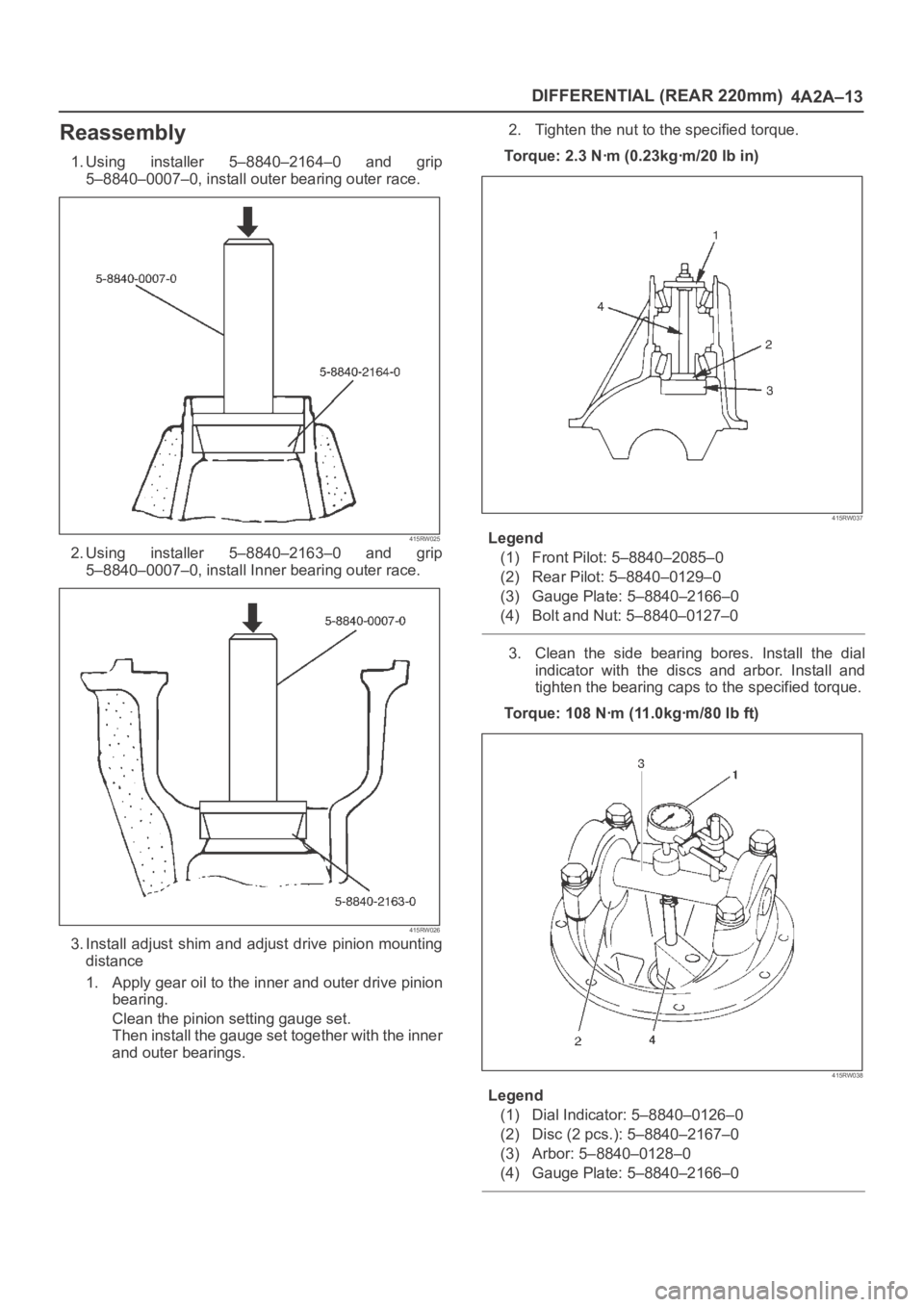
1. Using installer 5–8840–2164–0 and grip
5–8840–0007–0, install outer bearing outer race.
415RW025
2. Using installer 5–8840–2163–0 and grip
5–8840–0007–0, install Inner bearing outer race.
415RW026
3. Install adjust shim and adjust drive pinion mounting
distance
1. Apply gear oil to the inner and outer drive pinion
bearing.
Clean the pinion setting gauge set.
Then install the gauge set together with the inner
and outer bearings.2. Tighten the nut to the specified torque.
Torque: 2.3 Nꞏm (0.23kgꞏm/20 lb in)
415RW037
Legend
(1) Front Pilot: 5–8840–2085–0
(2) Rear Pilot: 5–8840–0129–0
(3) Gauge Plate: 5–8840–2166–0
(4) Bolt and Nut: 5–8840–0127–0
3. Clean the side bearing bores. Install the dial
indicator with the discs and arbor. Install and
tighten the bearing caps to the specified torque.
Torque: 108 Nꞏm (11.0kgꞏm/80 lb ft)
415RW038
Legend
(1) Dial Indicator: 5–8840–0126–0
(2) Disc (2 pcs.): 5–8840–2167–0
(3) Arbor: 5–8840–0128–0
(4) Gauge Plate: 5–8840–2166–0
Page 483 of 6000
4A2A–16
DIFFERENTIAL (REAR 220mm)
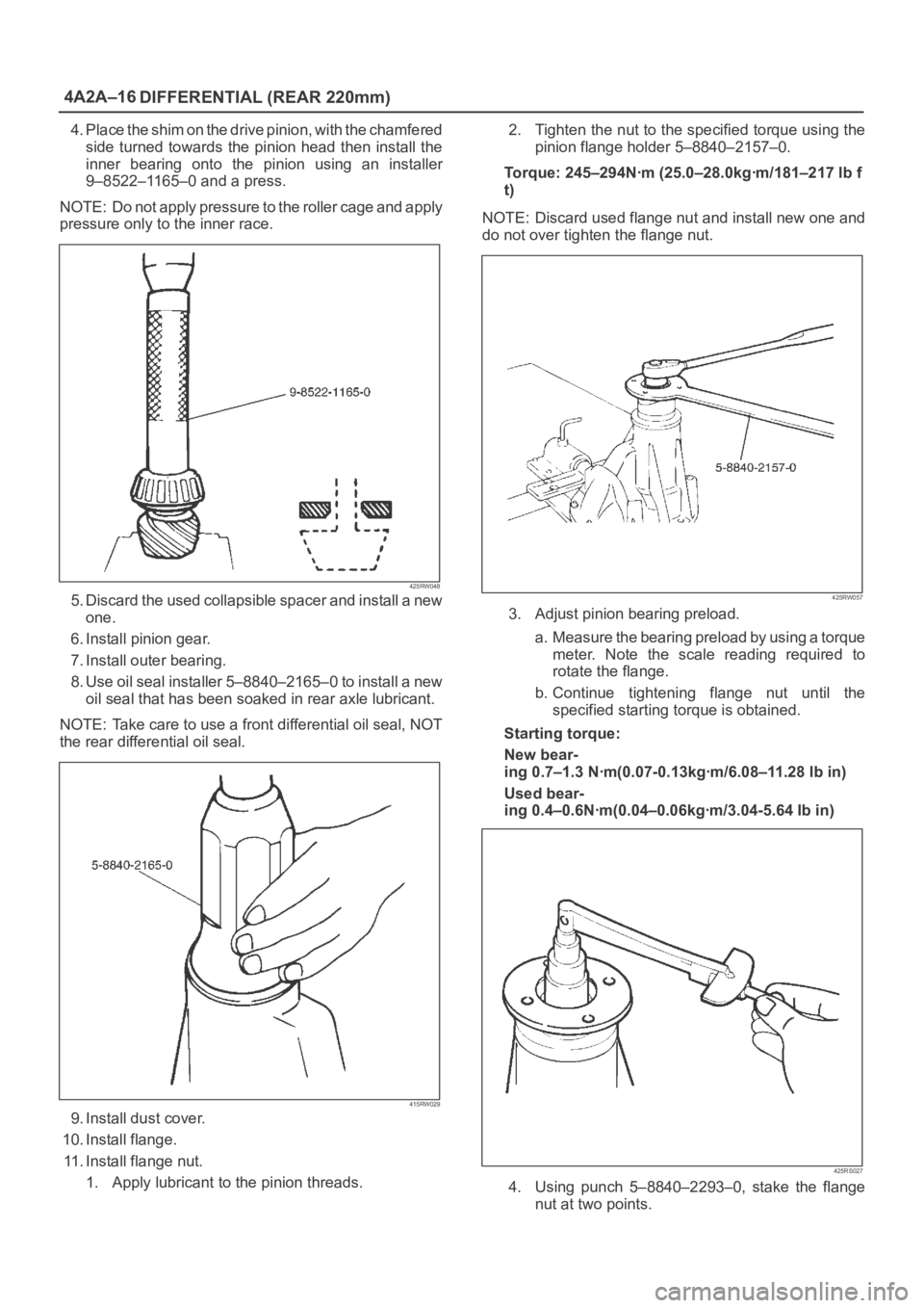
4. Place the shim on the drive pinion, with the chamfered
side turned towards the pinion head then install the
inner bearing onto the pinion using an installer
9–8522–1165–0 and a press.
NOTE: Do not apply pressure to the roller cage and apply
pressure only to the inner race.
425RW048
5. Discard the used collapsible spacer and install a new
one.
6. Install pinion gear.
7. Install outer bearing.
8. Use oil seal installer 5–8840–2165–0 to install a new
oil seal that has been soaked in rear axle lubricant.
NOTE: Take care to use a front differential oil seal, NOT
the rear differential oil seal.
415RW029
9. Install dust cover.
10. Install flange.
11. Install flange nut.
1. Apply lubricant to the pinion threads.2. Tighten the nut to the specified torque using the
pinion flange holder 5–8840–2157–0.
Torque: 245–294Nꞏm (25.0–28.0kgꞏm/181–217 lb f
t)
NOTE: Discard used flange nut and install new one and
do not over tighten the flange nut.
425RW057
3. Adjust pinion bearing preload.
a. Measure the bearing preload by using a torque
meter. Note the scale reading required to
rotate the flange.
b. Continue tightening flange nut until the
specified starting torque is obtained.
Starting torque:
New bear-
ing 0.7–1.3 Nꞏm(0.07-0.13kgꞏm/6.08–11.28 lb in)
Used bear-
ing 0.4–0.6Nꞏm(0.04–0.06kgꞏm/3.04-5.64 Ib in)
425RS027
4. Using punch 5–8840–2293–0, stake the flange
nut at two points.
Page 501 of 6000
4A2A–34
DIFFERENTIAL (REAR 220mm)
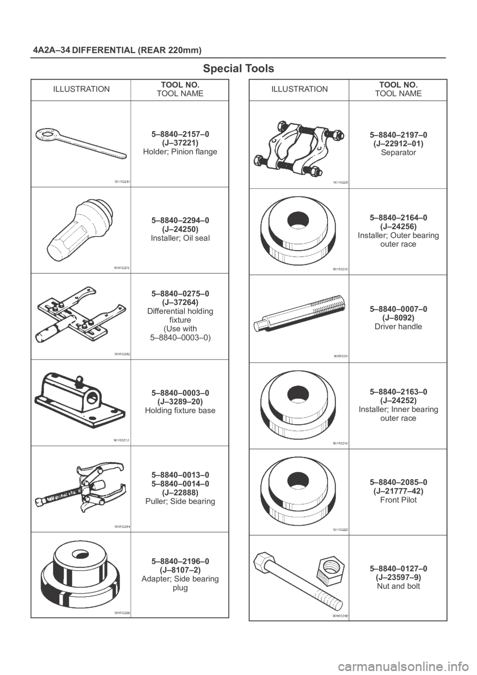
Special Tools
ILLUSTRATIONTOOL NO.
TOOL NAME
5–8840–2157–0
(J–37221)
Holder; Pinion flange
5–8840–2294–0
(J–24250)
Installer; Oil seal
5–8840–0275–0
(J–37264)
Differential holding
fixture
(Use with
5–8840–0003–0)
5–8840–0003–0
(J–3289–20)
Holding fixture base
5–8840–0013–0
5–8840–0014–0
(J–22888)
Puller; Side bearing
5–8840–2196–0
(J–8107–2)
Adapter; Side bearing
plug
ILLUSTRATIONTOOL NO.
TOOL NAME
5–8840–2197–0
(J–22912–01)
Separator
5–8840–2164–0
(J–24256)
Installer; Outer bearing
outer race
5–8840–0007–0
(J–8092)
Driver handle
5–8840–2163–0
(J–24252)
Installer; Inner bearing
outer race
5–8840–2085–0
(J–21777–42)
Front Pilot
5–8840–0127–0
(J–23597–9)
Nut and bolt
Page 506 of 6000
DIFFERENTIAL (REAR 244mm)
4A2B–3
Diagnosis
Many noises that seem to come from the rear axle
actually originate from other sources such as tires, road
surface, wheel bearings, engine, transmission, muffler, or
body drumming. Investigate to find the source of the
noise before disassembling the rear axle. Rear axles, like
any other mechanical device, are not absolutely quiet but
should be considered quiet unless some abnormal noise
is present.
To make a systematic check for axle noise, observe the
following:
1. Select a level asphalt road to reduce tire noise and
body drumming.
2. Check rear axle lubricant level to assure correct level,
and then drive the vehicle far enough to thoroughly
warm up the rear axle lubricant.
3. Note the speed at which noise occurs. Stop the
vehicle and put the transmission in neutral. Run the
engine speed slowly up and down to determine if the
noise is caused by exhaust, muffler noise, or other
engine conditions.
4. Tire noise changes with different road surfaces; axle
noises do not. Temporarily inflate all tires to 344 kPa
(3.5kg/cm
2, 50 psi) (for test purposes only). This will
change noise caused by tires but will not affect noise
caused by the rear axle.
Rear axle noise usually stops when coasting at
speeds under 48 km/h (30 mph); however, tire noise
continues with a lower tone. Rear axle noise usually
changes when comparing pull and coast, but tire
noise stays about the same.
Distinguish between tire noise and rear axle noise by
noting if the noise changes with various speeds or
sudden acceleration and deceleration. Exhaust and
axle noise vary under these conditions, while tire
noise remains constant and is more pronounced at
speeds of 32 to 48 km/h (20 to 30 mph). Further check
for tire noise by driving the vehicle over smooth
pavements or dirt roads (not gravel) with the tires at
normal pressure. If the noise is caused by tires, it will
change noticeably with changes in road surface.
5. Loose or rough front wheel bearings will cause noise
which may be confused with rear axle noise; however,
front wheel bearing noise does not change when
comparing drive and coast. Light application of the
brake while holding vehicle speed steady will often
cause wheel bearing noise to diminish. Front wheel
bearings may be checked for noise by jacking up the
wheels and spinning them or by shaking the wheels to
determine if bearings are loose.
6. Rear suspension rubber bushings and spring
insulators dampen out rear axle noise when correctly
installed. Check to see that there is no link or rod
loosened or metal–to–metal contact.
7. Make sure that there is no metal–to–metal contact
between the floor and the frame.
After the noise has been determined to be in the axle, the
type of axle noise should be determined, in order to make
any necessary repairs.
Gear Noise
Gear noise (whine) is audible from 32 to 89 km/h (20 to 55
mph) under four driving conditions.
1. Driving under acceleration or heavy pull.
2. Driving under load or under constant speed.
3. When using enough throttle to keep the vehicle from
driving the engine while the vehicle slows down
gradually (engine still pulls slightly).
4. When coasting with the vehicle in gear and the throttle
closed. The gear noise is usually more noticeable
between 48 and 64 km/h (30 and 40 mph) and 80 and
89 km/h (50 and 55 mph).
Bearing Noise
Bad bearings generally produce a rough growl or grating
sound, rather than the whine typical of gear noise.
Bearing noise frequently “wow–wows” at bearing rpm,
indicating a bad pinion or rear axle side bearing. This
noise can be confused with rear wheel bearing noise.
Rear Wheel Bearing Noise
Rear wheel bearing noise continues to be heard while
coasting at low speed with transmission in neutral. Noise
may diminish by gentle braking. Jack up the rear wheels,
spin them by hand and listen for noise at the hubs.
Replace any faulty wheel bearings.
Knock At Low Speeds
Low speed knock can be caused by worn universal joints
or a side gear hub counter bore in the cage that is worn
oversize. Inspect and replace universal joints or cage and
side gears as required.
Backlash Clunk
Excessive clunk on acceleration and deceleration can be
caused by a worn rear axle pinion shaft, a worn cage,
excessive clearance between the axle and the side gear
splines, excessive clearance between the side gear hub
and the counterbore in the cage, worn pinion and side
gear teeth, worn thrust washers, or excessive drive pinion
and ring gear backlash. Remove worn parts and replace
as required. Select close–fitting parts when possible.
Adjust pinion and ring gear backlash.
Page 657 of 6000
DRIVE LINE CONTROL SYSTEM (TOD) 4B2–86
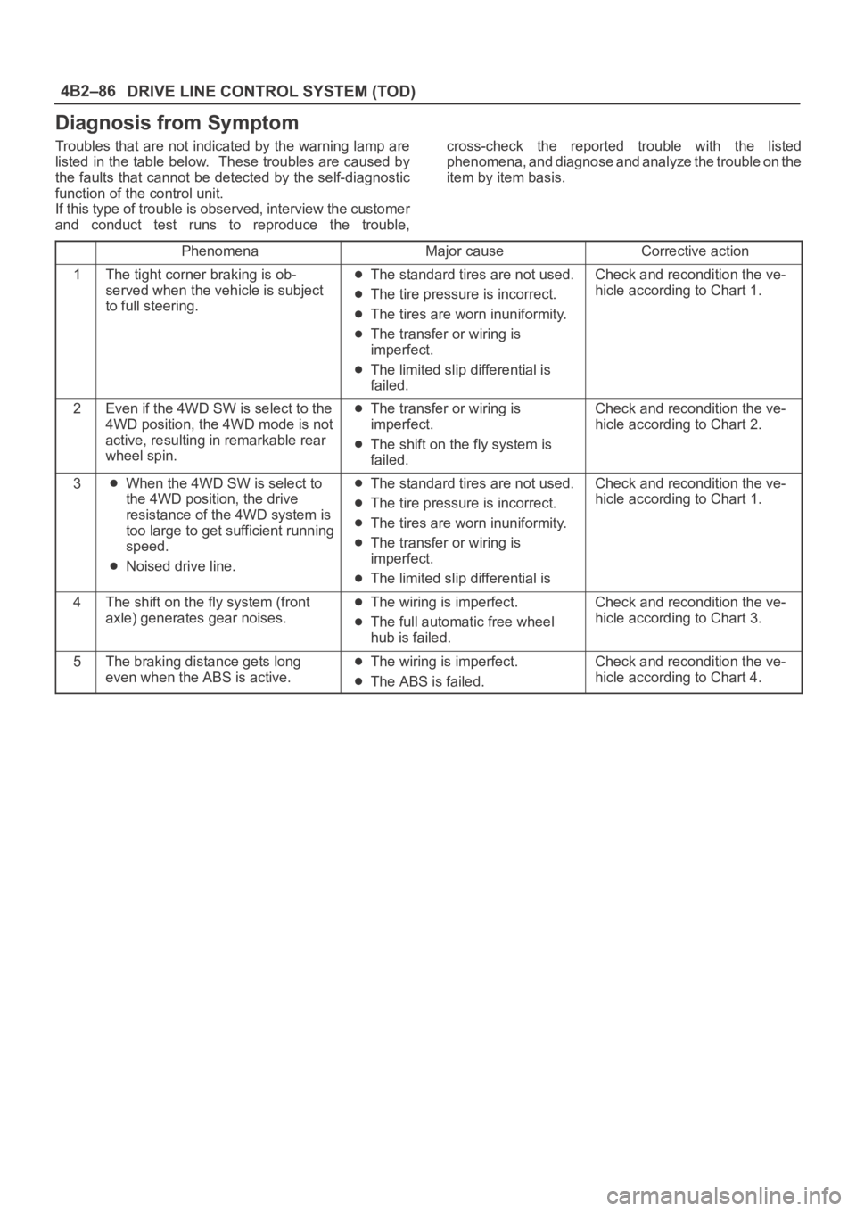
Diagnosis from Symptom
Troubles that are not indicated by the warning lamp are
listed in the table below. These troubles are caused by
the faults that cannot be detected by the self-diagnostic
function of the control unit.
If this type of trouble is observed, interview the customer
and conduct test runs to reproduce the trouble,cross-check the reported trouble with the listed
phenomena, and diagnose and analyze the trouble on the
item by item basis.
PhenomenaMajor causeCorrective action
1The tight corner braking is ob-
served when the vehicle is subject
to full steering.The standard tires are not used.
The tire pressure is incorrect.
The tires are worn inuniformity.
The transfer or wiring is
imperfect.
The limited slip differential is
failed.
Check and recondition the ve-
hicle according to Chart 1.
2Even if the 4WD SW is select to the
4WD position, the 4WD mode is not
active, resulting in remarkable rear
wheel spin.The transfer or wiring is
imperfect.
The shift on the fly system is
failed.
Check and recondition the ve-
hicle according to Chart 2.
3When the 4WD SW is select to
the 4WD position, the drive
resistance of the 4WD system is
too large to get sufficient running
speed.
Noised drive line.
The standard tires are not used.
The tire pressure is incorrect.
The tires are worn inuniformity.
The transfer or wiring is
imperfect.
The limited slip differential is
Check and recondition the ve-
hicle according to Chart 1.
4The shift on the fly system (front
axle) generates gear noises.The wiring is imperfect.
The full automatic free wheel
hub is failed.
Check and recondition the ve-
hicle according to Chart 3.
5The braking distance gets long
even when the ABS is active.The wiring is imperfect.
The ABS is failed.
Check and recondition the ve-
hicle according to Chart 4.
Page 659 of 6000
DRIVE LINE CONTROL SYSTEM (TOD) 4B2–88
StepActionYe sNo
1Are the front and rear tires in specified size?
Go to Step 2
Replace the tires
with specified
ones, and service
the new tires.
Go to Step 16
2Is the tire pressure correct?
Go to Step 3
Replace the tires
with specified
ones, and service
the new tires.
Go to Step 16
3Are the tires free from abnormal wear?
Go to Step 4
Replace the tires
with specified
ones, and service
the new tires.
Go to Step 16
4Are different types of tires used?
Go to Step 5
Replace the tires
with specified
ones, and service
the new tires.
Go to Step 16
51. Start the engine.
2. Shift the transfer lever to the high (TOD) position.
3. Fully turn the steering to the left (or right) end, and select the D
range and start the creep run.
Does the tight corner braking occur? Is the judder with chug-chug
sound observed? * Use caution on the operation.
Go to Step 6 Go to Step 11
61. Shift the transfer lever to the 2H position.
2. Fully turn the steering to the left (or right) end, and select the D
range and start the creep run.
Does the tight corner braking occur? Is the judder with chug-chug
sound observed? * Use caution on the operation.
Go to Step 7 Go to Step 14
7Is an LSD mounted to the rear differential? Go to Step 8 Go to Step 9
8Is the genuine LSD oil used in the rear differential?
Go to Step 9
Replace the
differential oil.
Go to Step 16
9Does the engine output the power correctly?
Go to Step 10
Check the
engine.
Go to Step 16
10Do the speed sensors work correctly? (Check trouble codes.)The ECU has
failed. Replace
the ECU.
Go to Step 16
Replace the
speed sensors.
Go to Step 16
11Is the tight corner braking observed only when the brake is
applied?
Go to Step 12
Conduct full
steering under
WOT.
Go to Step 5
121. Turn off the starter switch.
2. Disconnect the ECU connector.
Is the battery voltage observed between terminals (B–68)6 and
(B–67)11?
Go to Step 13
Repair the circuit
of terminal 6
(ABS IN).
Go to Step 16
Page 669 of 6000
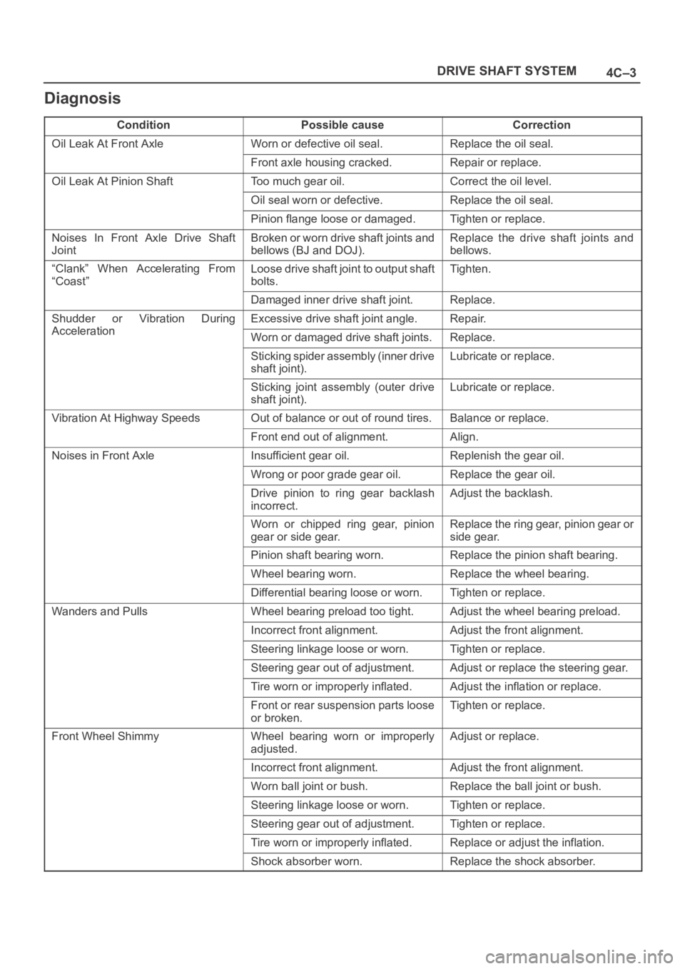
4C–3 DRIVE SHAFT SYSTEM
Diagnosis
ConditionPossible causeCorrection
Oil Leak At Front AxleWorn or defective oil seal.Replace the oil seal.
Front axle housing cracked.Repair or replace.
Oil Leak At Pinion ShaftToo much gear oil.Correct the oil level.
Oil seal worn or defective.Replace the oil seal.
Pinion flange loose or damaged.Tighten or replace.
Noises In Front Axle Drive Shaft
JointBroken or worn drive shaft joints and
bellows (BJ and DOJ).Replace the drive shaft joints and
bellows.
“Clank” When Accelerating From
“Coast”Loose drive shaft joint to output shaft
bolts.Tighten.
Damaged inner drive shaft joint.Replace.
Shudder or Vibration During
Acceleration
Excessive drive shaft joint angle.Repair.
AccelerationWorn or damaged drive shaft joints.Replace.
Sticking spider assembly (inner drive
shaft joint).Lubricate or replace.
Sticking joint assembly (outer drive
shaft joint).Lubricate or replace.
Vibration At Highway SpeedsOut of balance or out of round tires.Balance or replace.
Front end out of alignment.Align.
Noises in Front AxleInsufficient gear oil.Replenish the gear oil.
Wrong or poor grade gear oil.Replace the gear oil.
Drive pinion to ring gear backlash
incorrect.Adjust the backlash.
Worn or chipped ring gear, pinion
gear or side gear.Replace the ring gear, pinion gear or
side gear.
Pinion shaft bearing worn.Replace the pinion shaft bearing.
Wheel bearing worn.Replace the wheel bearing.
Differential bearing loose or worn.Tighten or replace.
Wanders and PullsWheel bearing preload too tight.Adjust the wheel bearing preload.
Incorrect front alignment.Adjust the front alignment.
Steering linkage loose or worn.Tighten or replace.
Steering gear out of adjustment.Adjust or replace the steering gear.
Tire worn or improperly inflated.Adjust the inflation or replace.
Front or rear suspension parts loose
or broken.Tighten or replace.
Front Wheel ShimmyWheel bearing worn or improperly
adjusted.Adjust or replace.
Incorrect front alignment.Adjust the front alignment.
Worn ball joint or bush.Replace the ball joint or bush.
Steering linkage loose or worn.Tighten or replace.
Steering gear out of adjustment.Tighten or replace.
Tire worn or improperly inflated.Replace or adjust the inflation.
Shock absorber worn.Replace the shock absorber.
Page 689 of 6000
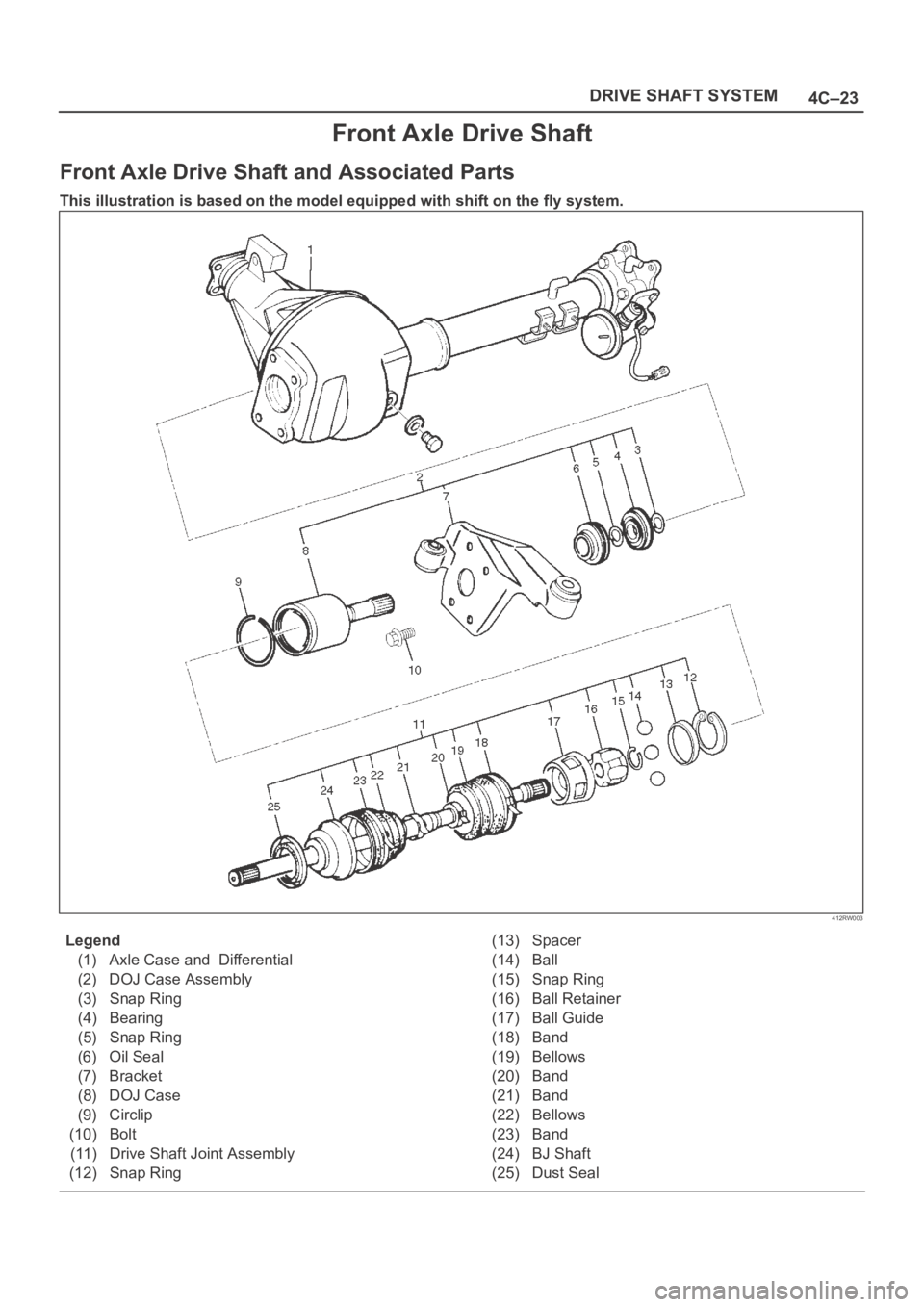
4C–23 DRIVE SHAFT SYSTEM
Front Axle Drive Shaft
Front Axle Drive Shaft and Associated Parts
This illustration is based on the model equipped with shift on the fly system.
412RW003
Legend
(1) Axle Case and Differential
(2) DOJ Case Assembly
(3) Snap Ring
(4) Bearing
(5) Snap Ring
(6) Oil Seal
(7) Bracket
(8) DOJ Case
(9) Circlip
(10) Bolt
(11) Drive Shaft Joint Assembly
(12) Snap Ring(13) Spacer
(14) Ball
(15) Snap Ring
(16) Ball Retainer
(17) Ball Guide
(18) Band
(19) Bellows
(20) Band
(21) Band
(22) Bellows
(23) Band
(24) BJ Shaft
(25) Dust Seal