key battery OPEL FRONTERA 1998 Owner's Guide
[x] Cancel search | Manufacturer: OPEL, Model Year: 1998, Model line: FRONTERA, Model: OPEL FRONTERA 1998Pages: 6000, PDF Size: 97 MB
Page 3462 of 6000
SUPPLEMENTAL RESTRAINT SYSTEM9J–25
TO ANY POWER SOURCE BEFORE CONNECTING
DEPLOYMENT WIRES TO THE PRETENSIONER
SEAT BELT ASSEMBLY LEADS. DEPLOYMENT
WIRES SHALL REMAIN SHORTED AND NOT BE
CONNECTED TO A POWER SOURCE UNTIL THE
PRETENSIONER SEAT BELT IS TO BE DEPLOYED.
THE PRETENSIONER SEAT BELT ASSEMBLY WILL
IMMEDIATELY DEPLOY THE PRETENSIONER SEAT
BELT WHEN A POWER SOURCE IS CONNECTED TO
IT. WEAR SAFETY GLASSES THROUGHOUT THIS
ENTIRE DEPLOYMENT AND DISPOSAL
PROCEDURE.
1. Turn ignition switch to “LOCK,” remove key and put
on safety glasses.
2. Remove all loose objects from front seats.
3. Disconnect pretensioner seat belt assembly, yellow
2–pin connector located at the base of the seat.
4. Prepare SRS deployment harness.
5. Short the two SRS deployment harness leads
together by fully seating one banana plug into the
other.
6. Deployment harness shall remain shorted and not be
connected to a power source until the pretensioner
seat belt is to be deployed.
7. Route deployment harness out the driver side of the
vehicle.
8. Verify that the inside of the vehicle and the area
surrounding the vehicle are clear of all people and
loose or flammable objects.
9. Stretch the SRS deployment harness to their full
length.
10. Connect the deployment harness to the pretensioner
seat belt assembly, yellow 2-pin connector at the
base of the seat.
WARNING: DEPLOYMENT WIRES SHALL REMAIN
SHORTED AND NOT BE CONNECTED TO A POWER
SOURCE UNTIL THE PRETENSIONER SEAT BELT IS
TO BE DEPLOYED. THE PRETENSIONER SEAT
BELT ASSEMBLY WILL IMMEDIATELY DEPLOY THE
PRETENSIONER SEAT BELT WHEN A POWER
SOURCE IS CONNECTED TO IT. CONNECTING THE
DEPLOYMENT WIRES TO THE POWER SOURCE
SHOULD ALWAYS BE THE FINAL STEP IN THE
PRETENSIONER SEAT BELT ASSEMBLY
DEPLOYMENT PROCEDURE. FAILURE TO FOLLOW
PROCEDURES IN THE ORDER LISTED COULD
RESULT IN PERSONAL INJURY.
11. Notify all people in the immediate area that you intend
to deploy the pretensioner seat belt. The deployment
will be accompanied by a substantial noise which may
startle the uninformed.
12. Separate the two banana plugs on the SRS
deployment harness.
NOTE: When the pretensioner seat belt deploys, the
rapid gas expansion will create a substantial noise. Notify
all people in the immediate area that you intend to deploy
the pretensioner seat belt.13. Connect the SRS deployment harness wires to a
power source to immediately deploy the pretensioner
seat belt assembly. Recommended application: 12
volts minimum, 2 amps minimum. A vehicle battery is
suggested.
WARNING: DEPLOYMENT WIRES SHALL REMAIN
SHORTED AND NOT BE CONNECTED TO A POWER
SOURCE UNTIL THE PRETENSIONER SEAT BELT IS
TO IS TO BE DEPLOYED. THE PRETENSIONER
SEAT BELT ASSEMBLY WILL IMMEDIATELY
DEPLOY THE PRETENSIONER SEAT BELT WHEN A
POWER SOURCE IS CONNECTED TO IT.
CONNECTING THE DEPLOYMENT WIRES SHOULD
ALWAYS BE THE FINAL STEP IN THE
PRETENSIONER SEAT BELT ASSEMBLY
DEPLOYMENT PROCEDURE. FAILURE TO FOLLOW
PROCEDURES IN THE ORDER LISTED COULD
RESULT IN PERSONAL INJURY.
14. Short the two SRS deployment harness leads
together by fully seating one banana plug into the
other.
15. Disconnect the deployment harness to the
pretensioner seat belt assembly, yellow 2-pin
connector at the base of the seat.
16. In the unlikely event that the pretensioner seat belt
assembly did not deploy after following these
procedures, proceed immediately with Steps 18
through 19. If the pretensioner seat belt assembly
deployed as intended, proceed with Steps 14 through
17.
17. With both air bags and pretensioner seat belt
deployed, the vehicle may be scrapped in the same
manner as a non–SRS equipped vehicle.
NOTE: The remaining steps are to be followed in the
unlikely event that the pretensioner seat belt assembly
did not deploy after following these procedures.
18. Remove the undeployed pretensioner seat belt
assembly (s) from the vehicle. For pretensioner seat
belt assembly refer to in the “Pretensioner Seat Belt
Assembly Removal” in this manual.
19.Temporarily store the pretensioner seat belt
assembly with the deployment device facing up, away
from the surface upon which it rests.
Page 3467 of 6000
SUPPLEMENTAL RESTRAINT SYSTEM 9J–30
Service Precautions for SRS
Component Service
CAUTION: When fasteners are removed, always
reinstall them at the same location from which they
were removed. If a fastener needs to be replaced, use
the correct part number fastener for that application.
If the correct part number fastener is not available, a
fastener of equal size and strength (or stronger) may
be used. fasteners that are not reused, and those
requiring thread locking compound will be called
out. The correct torque value must be used when
installing fasteners that require it. If the above
conditions are not followed, parts or system damage
could result.
WARNING: WHEN PERFORMING SERVICE ON OR
AROUND SRS COMPONENTS OR SRS WIRING,
FOLLOW THE PROCEDURES LISTED BELOW TO
TEMPORARILY DISABLE THE SRS. FAILURE TO
FOLLOW PROCEDURES COULD RESULT IN
POSSIBLE AIR BAG DEPLOYMENT, PERSONAL
INJURY OR OTHERWISE UNNEEDED SRS REPAIRS.
The SDM in Driver–Passenger SRS can maintain
sufficient voltage to cause a deployment for up to 15
seconds after the ignition switch is turned “OFF,” the
battery is disconnected, or the fuse powering the SDM is
removed.
Many of the service procedures require removal of the
“C–21” fuse, and disconnection of the air bag assembly
from the deployment loop to avoid an accidental
deployment. If the air bag assembly is disconnected from
the deployment loop as noted in the “Disabling the SRS”
procedure that follows, service can begin immediately
without waiting for the 15 second time period to expire.
Disabling The SRS
Removal
Turn the ignition switch to “OFF” and turn the steering
wheel so that the vehicle’s wheels are pointing straight
ahead.
1. Remove SRS fuse “C–21” from left dash side lower
fuse block or disconnect battery.
2. Disconnect yellow 2–pin connector at the base of
steering column.
3 . R e m o v e g l o v e b o x a s s e m b l y ; R e f e r t o “ P a s s e n g e r a i r
bag assembly replacement” in this section.
4. Disconnect passenger air bag assembly yellow 2–pin
connector behind the glove box assembly.
CAUTION: W i t h t h e “ C – 2 1 ” f u s e r e m o v e d a n d
ignition switch “ON,” the “AIR BAG” warning lamp
will be “ON.” This is normal operation and does not
indicate an SRS malfunction.
Enabling The SRS
Installation
Turn ignition switch to “LOCK” and remove key.
1. Connect yellow 2–pin connector passenger air bag
assembly.2. Install glove box assembly. Refer to “Passenger Air
Bag Assembly Replacement” in this section.
3. Connect yellow 2–pin connector at the base of the
steering column.
4. Install “AIR BAG” fuse “C–21” to left dash side lower
fuse block or connect battery.
Turn ignition switch to “ON” and verify that the “AIR BAG”
warning lamp turn on 3.5 seconds and then turns “OFF.” If
it does not operate as described, perform the “SRS
Diagnostic System Check” in this section.
Handling / Installation / Diagnosis
1. Air bag assembly should not be subjected to
temperatures above 93
C (200F).
2. Air bag assembly, and SDM should not be used if they
have been dropped from a height of 100 centimeters
(3.28 feet) or more.
3. When a SDM is replaced, it must be oriented with the
arrow on the SDM pointing toward the front of the
vehicle. It is very important for the SDM to be located
flat on the mounting surface, parallel to the vehicle
datum line. It is important that the SDM mounting
surface is free of any dirt or other foreign material.
4. Do not apply power to the SRS unless all components
are connected or a diagnostic chart requests it, as
this will set a diagnostic trouble code.
5. The “SRS Diagnostic System Check” must be the
starting point of any SRS diagnostics. The “SRS
Diagnostic System Check” will verify proper “AIR
BAG” warning lamp operation and will lead you to the
correct chart to diagnose any SRS malfunctions.
Bypassing these procedures may result in extended
diagnostic time, incorrect diagnosis, and incorrect
parts replacements.
Inspections Required After An Accident
CAUTION: C e r t a i n S R S c o m p o n e n t s m u s t b e
replaced after a frontal crash involving air bag
deployment.
In all types of accidents regardless of “Air Bag”
deployment, visually inspect all of the following
components and replace as required:
— Driver air bag assembly
— Passenger air bag assembly
— Driver pretensioner assembly
— Passenger pretensioner assembly
— Steering wheel
— SRS coil assembly
— Steering column
— Knee bolster and instrument panel mounting
attachments
— Driver seat and belt
— Passenger seat and belt
—SDM
SDM always should be checked according to “SDM
Replacement Guidelines.”
Page 4393 of 6000
5A–43 BRAKE CONTROL SYSTEM
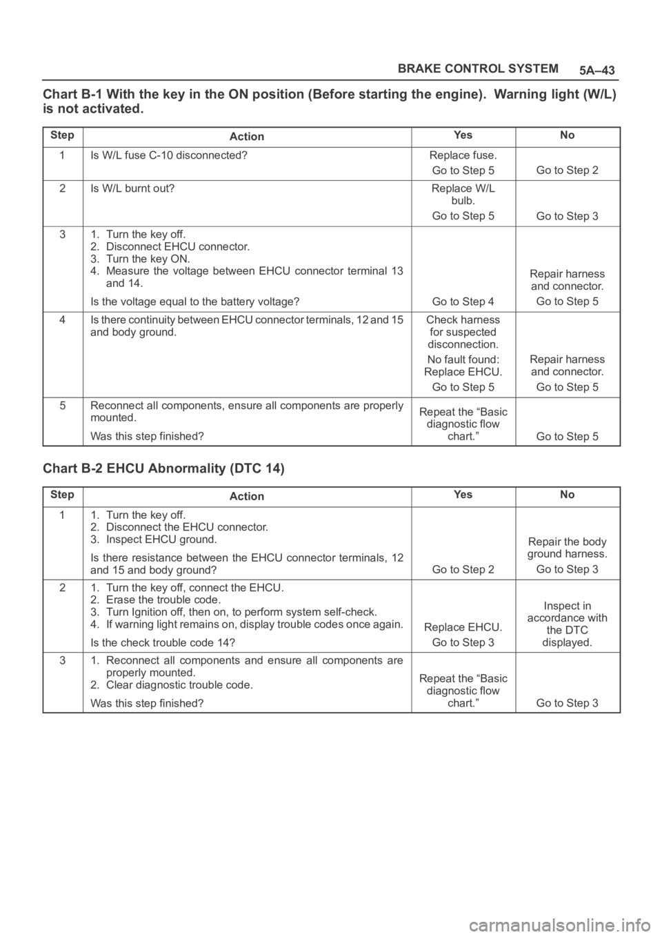
Chart B-1 With the key in the ON position (Before starting the engine). Warning light (W/L)
is not activated.
StepActionYe sNo
1Is W/L fuse C-10 disconnected?Replace fuse.
Go to Step 5
Go to Step 2
2Is W/L burnt out?Replace W/L
bulb.
Go to Step 5
Go to Step 3
31. Turn the key off.
2. Disconnect EHCU connector.
3. Turn the key ON.
4. Measure the voltage between EHCU connector terminal 13
and 14.
Is the voltage equal to the battery voltage?
Go to Step 4
Repair harness
and connector.
Go to Step 5
4Is there continuity between EHCU connector terminals, 12 and 15
and body ground.Check harness
for suspected
disconnection.
No fault found:
Replace EHCU.
Go to Step 5
Repair harness
and connector.
Go to Step 5
5Reconnect all components, ensure all components are properly
mounted.
Was this step finished?Repeat the “Basic
diagnostic flow
chart.”
Go to Step 5
Chart B-2 EHCU Abnormality (DTC 14)
StepActionYe sNo
11. Turn the key off.
2. Disconnect the EHCU connector.
3. Inspect EHCU ground.
Is there resistance between the EHCU connector terminals, 12
and 15 and body ground?
Go to Step 2
Repair the body
ground harness.
Go to Step 3
21. Turn the key off, connect the EHCU.
2. Erase the trouble code.
3. Turn Ignition off, then on, to perform system self-check.
4. If warning light remains on, display trouble codes once again.
Is the check trouble code 14?
Replace EHCU.
Go to Step 3
Inspect in
accordance with
the DTC
displayed.
31. Reconnect all components and ensure all components are
properly mounted.
2. Clear diagnostic trouble code.
Was this step finished?
Repeat the “Basic
diagnostic flow
chart.”
Go to Step 3
Page 4394 of 6000

5A–44
BRAKE CONTROL SYSTEM
Chart B-3 Power Voltage Drop (DTC 15)
StepActionYe sNo
1Is the battery voltage normal? (Battery capacity check)
Go to Step 2
Charge or
replace battery.
Go to Step 2
21. Turn the key off.
2. Disconnect EHCU connector.
3. Turn the key on.
Is the voltage between EHCU connector terminals 8 and 15,
higher than 10V?Check harness
connector for
suspected
disconnection.
Fault found:
Repair, and
perform system
self-check.
No fault found:
replace EHCU.
Go to Step 3
Repair harness or
connector.
Go to Step 3
31. Reconnect all components, ensure all components are
properly mounted.
2. Clear diagnostic trouble code.
Was this step finished?
Repeat the “Basic
diagnostic flow
chart.”
Go to Step 3
Chart B-4 CLASS-2 Communication Line Abnormality (DTC 16)
StepActionYe sNo
11. Turn the key off.
2. Disconnect EHCU and PCM connector.
Is there continuity between EHCU connector terminals 25 and
ground?
Go to Step 2
Repair harness or
connector.
Go to Step 3
21. Connect EHCU connector.
2. Clear diagnostic trouble code.
3. Turn the key on.
Is the diagnostic trouble code 16 shown on the displayed?Check the PCM
harness. Refer to
6E section.
Go to Step 3
Replace EHCU.
Go to Step 3
31. Reconnect all components, ensure all components are
properly mounted.
2. Clear diagnostic trouble code.
Was this step finished?
Repeat the “Basic
diagnostic flow
chart.”
Go to Step 3
Page 4396 of 6000

5A–46
BRAKE CONTROL SYSTEM
Chart B-6 Abnormal Transmission Input (DTC 23)
StepActionYe sNo
11. Turn the key off.
2. Disconnect EHCU connector.
Is there continuity between EHCU connector terminal 6 to 15
(Gear position-P(A/T), N(M/T))?Shorted switch
harness.
Repair switch or
harness.
Go to Step 6
Go to Step 2
2Is the vehicle an A/T model?Go to Step 3Go to Step 4
3Turn the key on and measure the voltage between EHCU
connector terminal 6 and 15.
Is the 6V under when the gear position is L, and R(Battery voltage
12V)?
Go to Step 5
Transmission SW
trouble.
Disconnected
harness.
Repair SW and
harness.
Go to Step 6
4Turn the key on and measure the voltage between EHCU
connector terminal 6 and 15.
Is the 9.6V over when the gear position is 1, 2, R(Battery voltage
12V)?
Go to Step 5
Transmission SW
trouble.
Disconnected
harness.
Repair SW and
harness.
Go to Step 6
5Is there 6.6 to 9.0V when the gear position is 3, 4, 5 and N(M/T) or
2,3,D,N and P(A/T)(Battery voltage 12V)?Suspected
harness/
connector short
power
source/GND.
Suspected
shorted
transmission SW.
Fault found:
repair, and
perform system
self-check.
No fault found:
replace EHCU.
Go to Step 6
Transmission SW
trouble.
Disconnected
harness.
Repair SW and
harness.
Go to Step 6
61. Reconnect all components, ensure all components are
properly mounted.
2. Clear diagnostic trouble code.
Was this step finished?
Repeat the “Basic
diagnostic flow
chart.”
Go to Step 6
Page 4397 of 6000
5A–47 BRAKE CONTROL SYSTEM
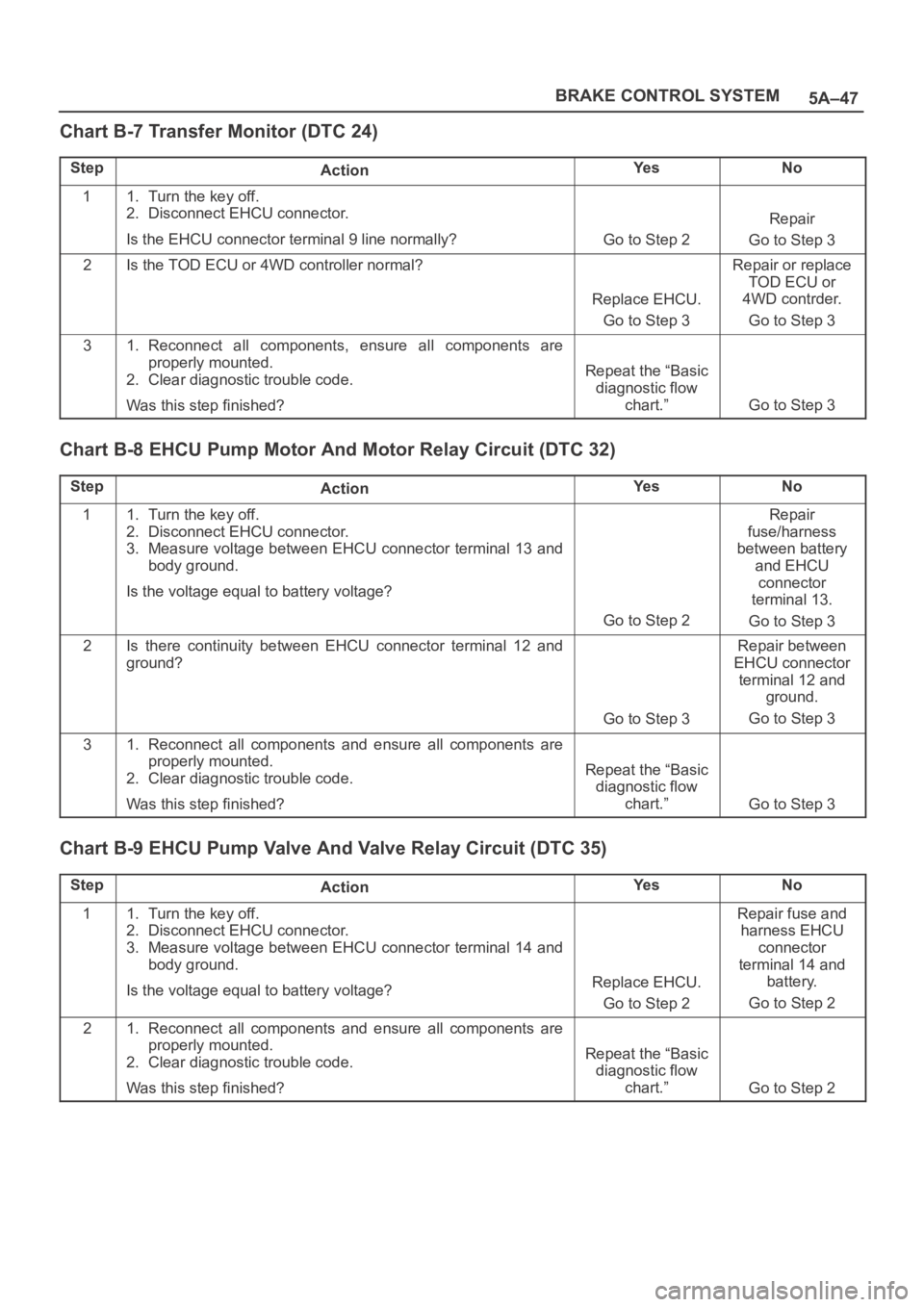
Chart B-7 Transfer Monitor (DTC 24)
StepActionYe sNo
11. Turn the key off.
2. Disconnect EHCU connector.
Is the EHCU connector terminal 9 line normally?
Go to Step 2
Repair
Go to Step 3
2Is the TOD ECU or 4WD controller normal?
Replace EHCU.
Go to Step 3
Repair or replace
TOD ECU or
4WD contrder.
Go to Step 3
31. Reconnect all components, ensure all components are
properly mounted.
2. Clear diagnostic trouble code.
Was this step finished?
Repeat the “Basic
diagnostic flow
chart.”
Go to Step 3
Chart B-8 EHCU Pump Motor And Motor Relay Circuit (DTC 32)
StepActionYe sNo
11. Turn the key off.
2. Disconnect EHCU connector.
3. Measure voltage between EHCU connector terminal 13 and
body ground.
Is the voltage equal to battery voltage?
Go to Step 2
Repair
fuse/harness
between battery
and EHCU
connector
terminal 13.
Go to Step 3
2Is there continuity between EHCU connector terminal 12 and
ground?
Go to Step 3
Repair between
EHCU connector
terminal 12 and
ground.
Go to Step 3
31. Reconnect all components and ensure all components are
properly mounted.
2. Clear diagnostic trouble code.
Was this step finished?
Repeat the “Basic
diagnostic flow
chart.”
Go to Step 3
Chart B-9 EHCU Pump Valve And Valve Relay Circuit (DTC 35)
StepActionYe sNo
11. Turn the key off.
2. Disconnect EHCU connector.
3. Measure voltage between EHCU connector terminal 14 and
body ground.
Is the voltage equal to battery voltage?
Replace EHCU.
Go to Step 2
Repair fuse and
harness EHCU
connector
terminal 14 and
battery.
Go to Step 2
21. Reconnect all components and ensure all components are
properly mounted.
2. Clear diagnostic trouble code.
Was this step finished?
Repeat the “Basic
diagnostic flow
chart.”
Go to Step 2
Page 4410 of 6000

5A–60
BRAKE CONTROL SYSTEM
Chart C-2 Transmission Input Inspection Procedure
StepActionYe sNo
11. Turn the key off.
2. Disconnect EHCU connector.
Is there continuity between EHCU connector terminals 6 and 15
(Gear position-P(A/T), N(M/T))?Shorted switch
harness.
Repair switch or
harness.
Go to Step 6
Go to Step 2
2Is the vehicle an A/T model?Go to Step 3Go to Step 5
3Turn the key on and measure voltage between EHCU connector
terminals 6 and 15.
Is there less than 6V when the gear position is L, and R(Battery
voltage 12V)?
Go to Step 5
Transmission SW
trouble.
Disconnected
harness.
Repair SW and
harness.
Go to Step 6
4Turn the key on and measure the voltage between EHCU
connector terminal 6 and 15.
Is there more than 9.6V when the gear position is 1, 2, R(Battery
voltage 12V)?
Go to Step 5
Transmission SW
trouble.
Disconnected
harness.
Repair SW and
harness.
Go to Step 6
5Measure the voltage between EHCU connector terminals 6 and
15.
Is there 6.6 to 9.0V when the gear position is 3, 4, 5 and N(M/T) or
2,3,D,N and P(A/T)(Battery voltage 12V)?
Go to Step 6
Transmission SW
trouble.
Disconnected
harness.
Repair SW and
harness.
Go to Step 6
61. Reconnect all components and ensure all components are
properly mounted.
2. Clear diagnostic trouble code.
Was this step finished?
Repeat the “Basic
diagnostic flow
chart.”
Go to Step 6
Page 4617 of 6000
6C–10
ENGINE FUEL
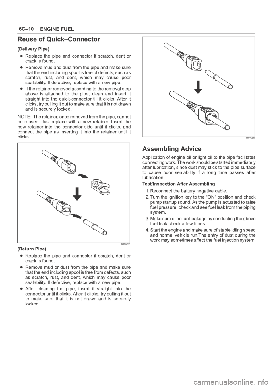
Reuse of Quick–Connector
(Delivery Pipe)
Replace the pipe and connector if scratch, dent or
crack is found.
Remove mud and dust from the pipe and make sure
that the end including spool is free of defects, such as
scratch, rust, and dent, which may cause poor
sealability. If defective, replace with a new pipe.
If the retainer removed according to the removal step
above is attached to the pipe, clean and insert it
straight into the quick-connector till it clicks. After it
clicks, try pulling it out to make sure that it is not drawn
and is securely locked.
NOTE: The retainer, once removed from the pipe, cannot
be reused. Just replace with a new retainer. Insert the
new retainer into the connector side until it clicks, and
connect the pipe as inserting it into the retainer until it
clicks.
141RW018
(Return Pipe)
Replace the pipe and connector if scratch, dent or
crack is found.
Remove mud or dust from the pipe and make sure
that the end including spool is free from defects, such
as scratch, rust, and dent, which may cause poor
sealability. If defective, replace with a new pipe.
After cleaning the pipe, insert it straight into the
connector until it clicks. After it clicks, try pulling it out
to make sure that it is not drawn and is securely
locked.
141RW017
Assembling Advice
Application of engine oil or light oil to the pipe facilitates
connecting work. The work should be started immediately
after lubrication, since dust may stick to the pipe surface
to cause poor sealability if a long time passes after
lubrication.
Test/Inspection After Assembling
1. Reconnect the battery negative cable.
2. Turn the ignition key to the “ON” position and check
pump startup sound. As the pump is actuated to raise
fuel pressure, check and see fuel leak from the piping
system.
3. Make sure of no fuel leakage by conducting the above
fuel leak check a few times.
4. Start the engine and make sure of stable idling speed
and normal vehicle run.The entry of dust during the
work may sometimes affect the fuel injection system.
Page 4699 of 6000
6E–42
ENGINE DRIVEABILITY AND EMISSIONS
Intermittent Malfunction Indicator Lamp
In the case of an “intermittent” fault, the MIL (“Check
Engine” lamp) may illuminate and then (after three trips)
go “OFF”. However, the corresponding diagnostic trouble
code will be stored in the memory. When unexpected
diagnostic trouble codes appear, check for an intermittent
malfunction.
A diagnostic trouble code may reset. Consult the
“Diagnostic Aids” associated with the diagnostic trouble
code. A physical inspection of the applicable sub-system
most often will resolve the problem.
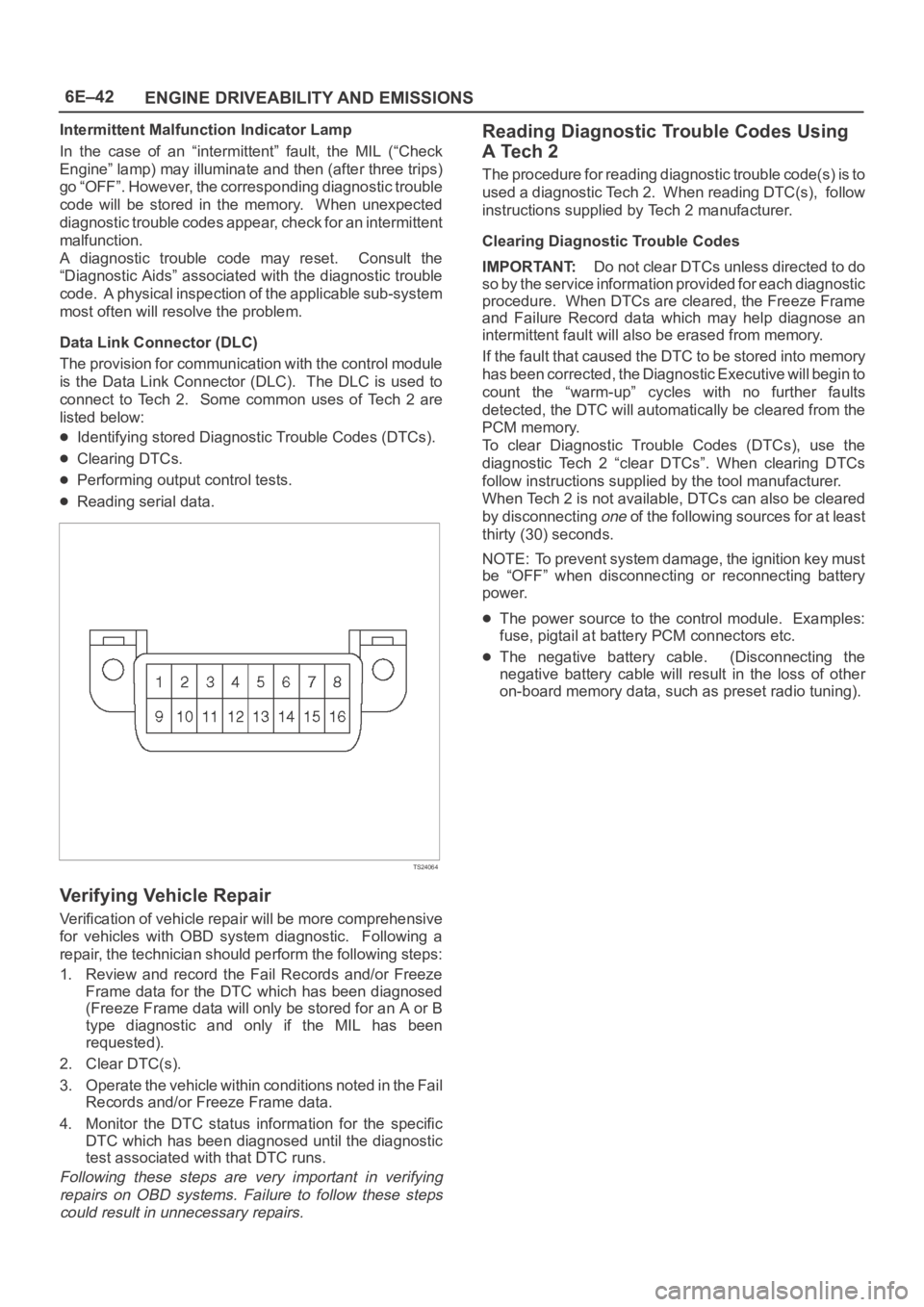
Data Link Connector (DLC)
The provision for communication with the control module
is the Data Link Connector (DLC). The DLC is used to
connect to Tech 2. Some common uses of Tech 2 are
listed below:
Identifying stored Diagnostic Trouble Codes (DTCs).
Clearing DTCs.
Performing output control tests.
Reading serial data.
TS24064
Verifying Vehicle Repair
Verification of vehicle repair will be more comprehensive
for vehicles with OBD system diagnostic. Following a
repair, the technician should perform the following steps:
1. Review and record the Fail Records and/or Freeze
Frame data for the DTC which has been diagnosed
(Freeze Frame data will only be stored for an A or B
type diagnostic and only if the MIL has been
requested).
2. Clear DTC(s).
3. Operate the vehicle within conditions noted in the Fail
Records and/or Freeze Frame data.
4. Monitor the DTC status information for the specific
DTC which has been diagnosed until the diagnostic
test associated with that DTC runs.
Following these steps are very important in verifying
repairs on OBD systems. Failure to follow these steps
could result in unnecessary repairs.
Reading Diagnostic Trouble Codes Using
A Tech 2
The procedure for reading diagnostic trouble code(s) is to
used a diagnostic Tech 2. When reading DTC(s), follow
instructions supplied by Tech 2 manufacturer.
Clearing Diagnostic Trouble Codes
IMPORTANT:Do not clear DTCs unless directed to do
so by the service information provided for each diagnostic
procedure. When DTCs are cleared, the Freeze Frame
and Failure Record data which may help diagnose an
intermittent fault will also be erased from memory.
If the fault that caused the DTC to be stored into memory
has been corrected, the Diagnostic Executive will begin to
count the “warm-up” cycles with no further faults
detected, the DTC will automatically be cleared from the
PCM memory.
To clear Diagnostic Trouble Codes (DTCs), use the
diagnostic Tech 2 “clear DTCs”. When clearing DTCs
follow instructions supplied by the tool manufacturer.
When Tech 2 is not available, DTCs can also be cleared
by disconnecting
one of the following sources for at least
thirty (30) seconds.
NOTE: To prevent system damage, the ignition key must
be “OFF” when disconnecting or reconnecting battery
power.
The power source to the control module. Examples:
fuse, pigtail at battery PCM connectors etc.
The negative battery cable. (Disconnecting the
negative battery cable will result in the loss of other
on-board memory data, such as preset radio tuning).
Page 4772 of 6000

6E–115 ENGINE DRIVEABILITY AND EMISSIONS
Diagnostic Trouble Code (DTC) P0108 MAP Sensor Circuit High Voltage
D06RW102
Circuit Description
The manifold absolute pressure (MAP) sensor responds
to changes in intake manifold pressure (vacuum). The
MAP sensor signal voltage to the powertrain control
module (PCM) varies from below 2 volts at idle (high
vacuum) to above 4 volts with the key “ON,” engine not
running or at wide-open throttle (low vacuum).
The MAP sensor is used to determine manifold pressure
changes while the linear EGR flow test diagnostic is being
run (refer to
DTC P0401), to determine engine vacuum
level for some other diagnostics and to determine
barometric pressure (BARO). The PCM monitors the
MAP signals for voltages outside the normal range of the
MAP sensor. If the PCM detects a MAP signal voltage
that is excessively high, DTC P0108 will be set.
Conditions for Setting the DTC
No TP sensor DTCs present.
Engine is running for more than 10 seconds.
Throttle position is below 3% if engine speed is below
1000 RPM.
Throttle position is below 10% if engine speed is above
1000 RPM.
The MAP sensor indicates an intermittent manifold
absolute pressure above 80kPa for a total of
approximately 10 seconds over a 16-second period.
Action Taken When the DTC Sets
The PCM will illuminate the malfunction indicator lamp
(MIL) the first time the fault is detected.
The PCM will default to a BARO value of 79.3 kPa.
The PCM will store conditions which were present
when the DTC was set as Freeze Frame and in the
Failure Records data.
Conditions for Clearing the MIL/DTC
DTC P0108 can be cleared by using the Tech 2 “Clear
Info” function or by disconnecting the PCM battery
feed.
Diagnostic Aids
Check for the following conditions:
Poor connection at PCM – Inspect harness connectors
for backed-out terminals, improper mating, broken
locks, improperly formed or damaged terminals, and
poor terminal-to-wire connection.
Damaged harness – Inspect the wiring harness for
damage. If the harness appears to be OK, observe the
MAP display on the Tech 2 while moving connectors
and wiring harnesses related to the sensor. A change
in the display will indicate the location of the fault.
If DTC P0108 cannot be duplicated, the information
included in the Failure Records data can be useful in
determining vehicle mileage since the DTC was last set. If
it is determined that the DTC occurs intermittently,
performing the DTC P1108 Diagnostic Chart may isolate
the cause of the fault.