key battery OPEL FRONTERA 1998 User Guide
[x] Cancel search | Manufacturer: OPEL, Model Year: 1998, Model line: FRONTERA, Model: OPEL FRONTERA 1998Pages: 6000, PDF Size: 97 MB
Page 1873 of 6000

6D – 6 ENGINE ELECTRICAL
RELATION BETWEEN STARTER SWITCH AND STARTER
M
Key
PositionB1 B2 ACCIG1 IG2 ST
LOCKKey
Removed
Inserted OFF
ACC
ON
START
BSBattery
+-
2
17
3
4
5
6
Legend
(1) Starter Switch
(2) To Generator
(3) To QOS4 Control(4) Starter Relay
(5) Immobilizer Relay (for Europe)
(6) Magnetic Switch
(7) Battery
065R200029
Page 1921 of 6000
6E–28
4JX1–TC ENGINE DRIVEABILITY AND EMISSIONS
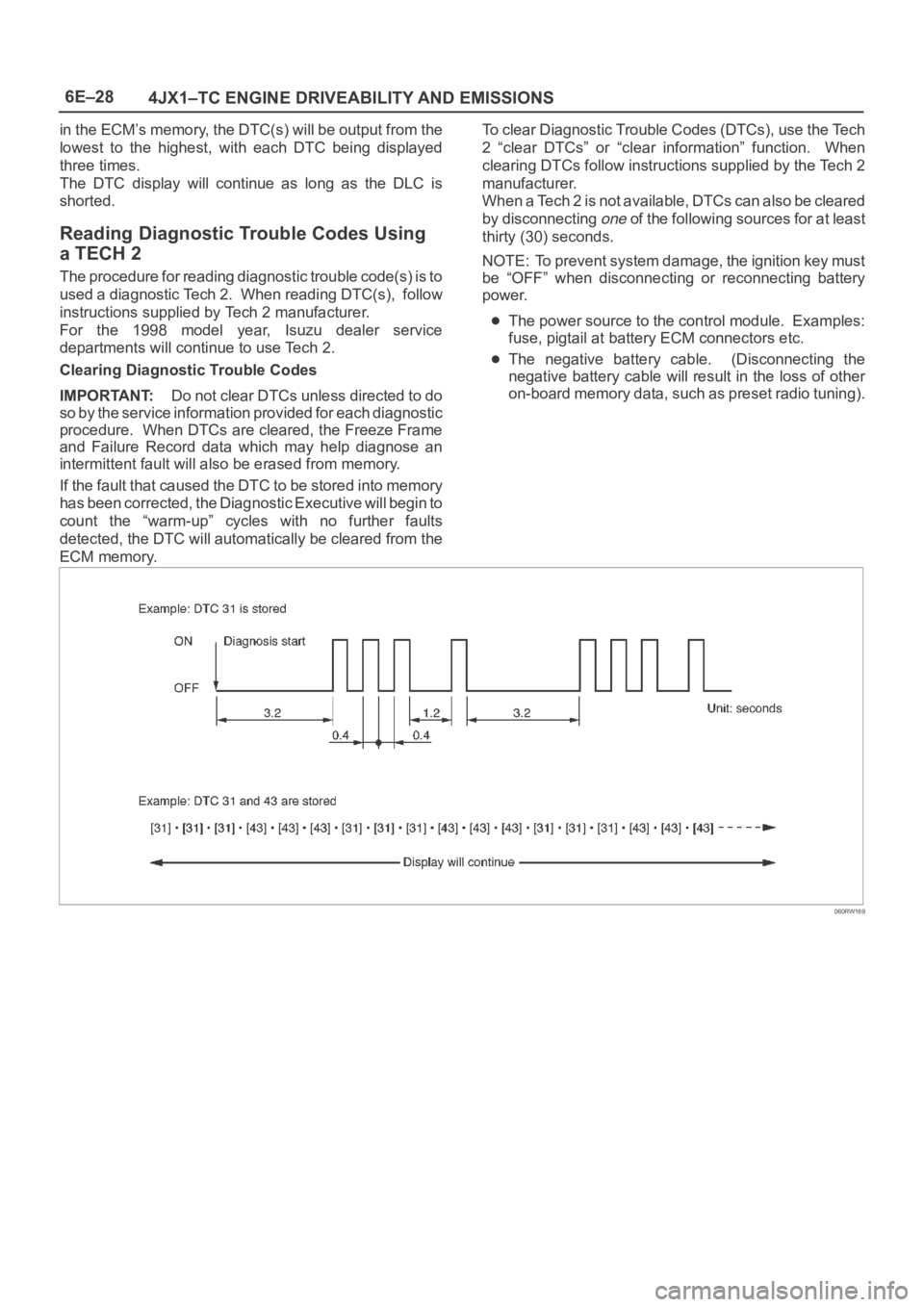
in the ECM’s memory, the DTC(s) will be output from the
lowest to the highest, with each DTC being displayed
three times.
The DTC display will continue as long as the DLC is
shorted.
Reading Diagnostic Trouble Codes Using
a TECH 2
The procedure for reading diagnostic trouble code(s) is to
used a diagnostic Tech 2. When reading DTC(s), follow
instructions supplied by Tech 2 manufacturer.
For the 1998 model year, Isuzu dealer service
departments will continue to use Tech 2.
Clearing Diagnostic Trouble Codes
IMPORTANT:Do not clear DTCs unless directed to do
so by the service information provided for each diagnostic
procedure. When DTCs are cleared, the Freeze Frame
and Failure Record data which may help diagnose an
intermittent fault will also be erased from memory.
If the fault that caused the DTC to be stored into memory
has been corrected, the Diagnostic Executive will begin to
count the “warm-up” cycles with no further faults
detected, the DTC will automatically be cleared from the
ECM memory.To clear Diagnostic Trouble Codes (DTCs), use the Tech
2 “clear DTCs” or “clear information” function. When
clearing DTCs follow instructions supplied by the Tech 2
manufacturer.
When a Tech 2 is not available, DTCs can also be cleared
by disconnecting
one of the following sources for at least
thirty (30) seconds.
NOTE: To prevent system damage, the ignition key must
be “OFF” when disconnecting or reconnecting battery
power.
The power source to the control module. Examples:
fuse, pigtail at battery ECM connectors etc.
The negative battery cable. (Disconnecting the
negative battery cable will result in the loss of other
on-board memory data, such as preset radio tuning).
060RW169
Page 1968 of 6000

6E–75 4JX1–TC ENGINE DRIVEABILITY AND EMISSIONS
Diagnostic Trouble Code (DTC) P0123 (Flash DTC 21)
AP Sensor High Voltage
060RW134
Circuit Description
The accelerator position (AP) sensor circuit provides a
voltage signal that changes relative to throttle blade
angle.
The TP signal is one of the most important inputs used by
the Engine Control Module ECM for fuel volume control
and many of the ECM-controlled outputs.
Action Taken When the DTC Sets
The ECM will store conditions which were present
when the DTC was set as Freeze Frame and in the
Failure Records data.
Conditions for Clearing the MIL/DTC
DTC P0123 can be cleared by using the Tech 2 “Clear
Info” function or by disconnecting the ECM battery
feed.
Diagnostic Aids
Check for the following conditions:
Poor connection at ECM – Inspect harness connectors
for backed-out terminals, improper mating, brokenlocks, improperly formed or damaged terminals, and
poor terminal-to-wire connection.
Damaged harness – Inspect the wiring harness for
damage. If the harness appears to be OK, observe the
AP sensor display on the Tech 2 while moving
connectors and wiring harnesses related to the TP
sensor. A change in the display will indicate the
location of the fault.
Faulty AP sensor – With the ignition key “ON,” engine
“OFF,” observe the AP sensor display on the Tech 2
while slowly depressing the accelerator to wide open
throttle. If a voltage over 4.88 volts is seen at any point
in normal accelerator travel, replace the AP sensor.
If DTC P0123 cannot be duplicated, the information
included in the Failure Records data can be useful in
determining vehicle mileage since the DTC was last set.
Test Description
Number (s) below refer to the step number(s) on the
Diagnostic Chart.
8. Components that share the AP sensor 5 volt reference
“A” circuit include the following device:
Page 2039 of 6000

6E–146
4JX1–TC ENGINE DRIVEABILITY AND EMISSIONS
Diagnostic Trouble Code (DTC) P1486 (Flash DTC 74)
ITP (Intake Throttle Position) Sensor High Voltage
060RW134
Circuit Description
The intake throttle position (ITP) sensor circuit provides a
voltage signal that changes relative to throttle blade
angle.
Action Taken When the DTC Sets
The ECM will illuminate the malfunction indicator lamp
(MIL) the first time the fault is detected.
The ECM will store conditions which were present
when the DTC was set as Freeze Frame and in the
Failure Records data.
Conditions for Clearing the MIL/DTC
DTC P1486 can be cleared by using the Tech 2 “Clear
Info” function or by disconnecting the ECM battery
feed.
Diagnostic Aids
Check for the following conditions:
Poor connection at ECM – Inspect harness connectors
for backed-out terminals, improper mating, broken
locks, improperly formed or damaged terminals, and
poor terminal-to-wire connection.
Damaged harness – Inspect the wiring harness for
damage. If the harness appears to be OK, observe the
ITP sensor display on the Tech 2 while moving
connectors and wiring harnesses related to the TP
sensor. A change in the display will indicate the
location of the fault.
Faulty TP sensor – With the ignition key “ON,” engine
“OFF,” observe the TP sensor display on the Tech 2
while slowly depressing the accelerator to wide open
throttle.
If DTC P1486 cannot be duplicated, the information
included in the Failure Records data can be useful in
determining vehicle mileage since the DTC was last set.
Page 2182 of 6000
7A–28
AUTOMATIC TRANSMISSION (4L30–E)
Removal
1. Disconnect battery ground cable.
2. Remove transfer control lever knob.
3. Remove front console.
Disconnect wiring harness connectors from front
console.
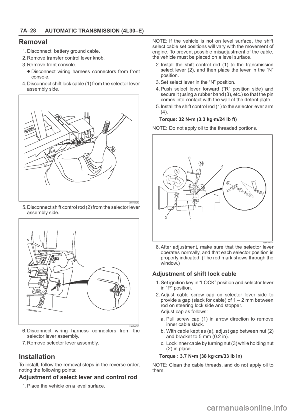
4. Disconnect shift lock cable (1) from the selector lever
assembly side.
256RW012
5. Disconnect shift control rod (2) from the selector lever
assembly side.
256RW013
6. Disconnect wiring harness connectors from the
selector lever assembly.
7. Remove selector lever assembly.
Installation
To install, follow the removal steps in the reverse order,
noting the following points:
Adjustment of select lever and control rod
1. Place the vehicle on a level surface.NOTE: If the vehicle is not on level surface, the shift
select cable set positions will vary with the movement of
engine. To prevent possible misadjustment of the cable,
the vehicle must be placed on a level surface.
2. Install the shift control rod (1) to the transmission
select lever (2), and then place the lever in the “N”
position.
3. Set select lever in the “N” position.
4. Push select lever forward (“R” position side) and
s e c u r e i t ( u s i n g a r u b b e r b a n d ( 3 ) , e t c . ) s o t h a t t h e p i n
comes into contact with the wall of the detent plate.
5. Install the shift control rod (1) to the selector lever arm
(4).
To r q u e : 3 2 N
m (3.3 kgꞏm/24 lb ft)
NOTE: Do not apply oil to the threaded portions.
256RW014
6. After adjustment, make sure that the selector lever
operates normally, and that each selector position is
properly indicated. (The red mark shows through the
window.)
Adjustment of shift lock cable
1. Set ignition key in “LOCK” position and selector lever
in “P” position.
2. Adjust cable screw cap on selector lever side to
provide a gap (slack for cable) of 1 – 2 mm between
rod on steering lock side and stopper.
Adjust cap as follows:
a. Pull screw cap (1) in arrow direction to remove
inner cable slack.
b. With cable kept as (a), adjust gap between nut (2)
and bracket to 5 mm (0.2 in).
c. Lock inner cable by turning nut (3) while holding nut
(2) in place.
Torque : 3.7 N
m (38 kgꞏcm/33 lb in)
NOTE: Clean the cable threads, and do not apply oil to
them.
Page 2183 of 6000
7A–29 AUTOMATIC TRANSMISSION (4L30–E)
256RW015
3. Check the shift lock operation:
a. Selector lever should not move out of “P” position
with ignition key in “Lock” position.
b. Selector lever can be moved out of “P” position with
ignition key in “ON” position only when brake pedal
is depressed.
c. Ignition key can be turned to “LOCK” position only
when selector lever is in “P” position (key can be
pulled out).
If (a) and (c) fail, readjust cable. If (b) fails, readjust
connector wiring and brake pedal switch.
Mode Switch
Removal
1. Place selector lever in neutral.
2. Disconnect battery ground cable.
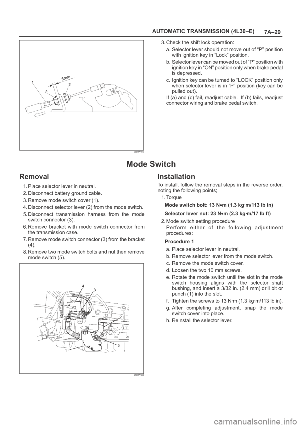
3. Remove mode switch cover (1).
4. Disconnect selector lever (2) from the mode switch.
5. Disconnect transmission harness from the mode
switch connector (3).
6. Remove bracket with mode switch connector from
the transmission case.
7. Remove mode switch connector (3) from the bracket
(4).
8. Remove two mode switch bolts and nut then remove
mode switch (5).
210RW008
Installation
To install, follow the removal steps in the reverse order,
noting the following points;
1. Torque
Mode switch bolt: 13 N
m(1.3kgꞏm/113lbin)
Selector lever nut: 23 N
m (2.3 kgꞏm/17 lb ft)
2. Mode switch setting procedure
Perform either of the following adjustment
procedures:
Procedure 1
a. Place selector lever in neutral.
b. Remove selector lever from the mode switch.
c. Remove the mode switch cover.
d. Loosen the two 10 mm screws.
e. Rotate the mode switch until the slot in the mode
switch housing aligns with the selector shaft
bushing, and insert a 3/32 in. (2.4 mm) drill bit or
punch (1) into the slot.
f. Tighten the screws to 13 Nꞏm (1.3 kgꞏm/113 lb in).
g. After completing adjustment, snap the mode
switch cover into place.
h. Reinstall the selector lever.
Page 2564 of 6000

LIGHTING SYSTEM8A–25
Seat Heater Switch
Removal
1. Disconnect the battery ground cable.
2. Remove four fixing screws and disconnect the switch
connectors to remove the front console assembly(4).
3. Push the lock from the back side of the front console
assembly to remove the seat heater switch(5).
825RW025
Installation
To install, follow the removal steps in the reverse order,
noting the following point.
1. Push the switch with your fingers until it locks
securely.
Key Remind Switch (Starter Switch)
Removal and Installation
Refer to the removal and installation on steps of the
Starter Switch in this section.
Page 2647 of 6000
3
P-2
H-142
2
B-11
P-10P-7
PCM
(A4)
CONDENSER
FANEHCU STARTER
(B)
STARTER
RELAY
(3)
P-6
BODY ENGINE FRAME
BATTERY
STARTER
SWRELAY & FUSE BOX
CONDENSER
FAN
RELAY
FL-2 50A
KEY SWFL-3 30A
PCMFL-4 30A
CONDENSER
FANFL-6 40A
ABS FL-1 80A
MAIN 8.0
B/R
8.0
B30.0
B8.0
B30.0
B/R
3.0
W/B
3.0
W/B
3.0
W/B
3.0
B/Y3.0
W/G3.0
B/R3.0
L/B2.0
W1.25
L/O
1.25
L3.0
W/G
3.0
W/B5.0
W
5.0
W
3.0
W/B
B-11IG1 ST IG2 ACC B1
7B-11
3B-11
5B-11
1
B2
OFF 4
B-11
P-5
P-1�+
�−
X-191
X-19
D08RWC56.
Page 2652 of 6000
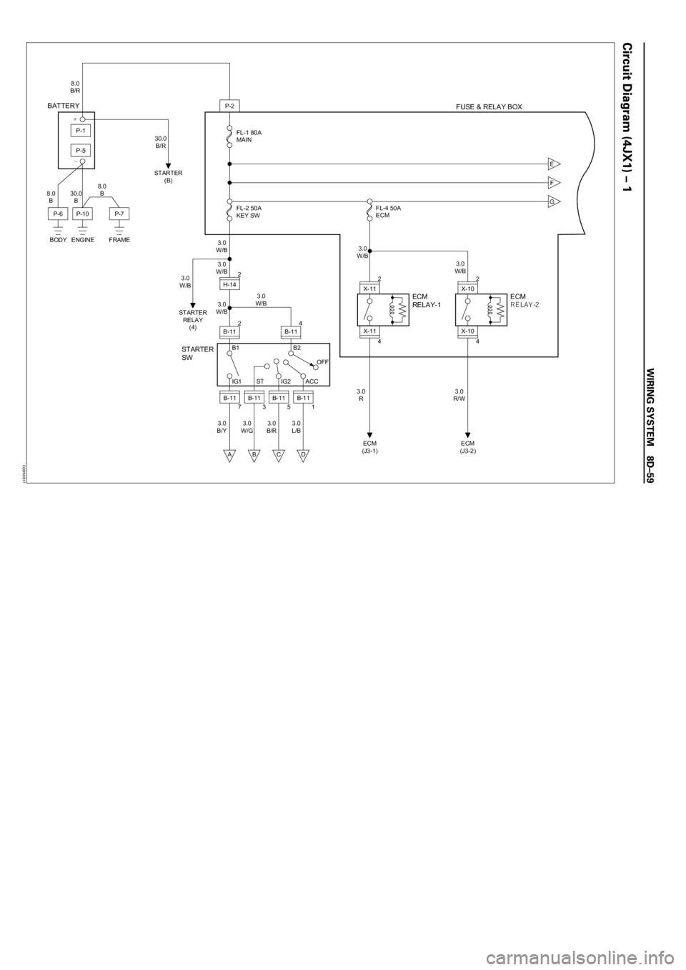
P-2
H-142
2
B-11
P-10P-7
STARTER
RELAY
(4)
P-6
BODY ENGINE FRAME
BATTERY
STARTER
SWFUSE & RELAY BOX
FL-2 50A
KEY SW FL-1 80A
MAIN 8.0
B/R
8.0
B30.0
B8.0
B
3.0
W/B
3.0
W/B
3.0
W/B
3.0
B/Y3.0
W/G3.0
B/R3.0
L/B 3.0
W/B 3.0
W/B 30.0
B/R
B-11IG1 ST IG2 ACC B1
7
E
F
G
A
B-11
3
B
B-11
5
C
B-11
1
D
B2
OFF 4
B-11
STARTER
(B)
P-5
P-1+
−
X-112
4
X-11
ECM
(J3-1)
ECM
RELAY-1
FL-4 50A
ECM
3.0
R 3.0
W/B
X-102
4
X-10
ECM
(J3-2)
ECM
RELAY-2
3.0
R/W3.0
W/B
D08RWB17
Page 2653 of 6000
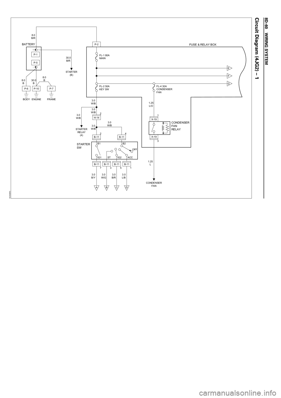
P-2
H-142
2
B-11
P-10P-7
STARTER
RELAY
(4)
P-6
BODY ENGINE FRAME
BATTERY
STARTER
SWFUSE & RELAY BOX
FL-2 50A
KEY SW FL-1 80A
MAIN 8.0
B/R
8.0
B30.0
B8.0
B
3.0
W/B
3.0
W/B
3.0
W/B
3.0
B/Y3.0
W/G3.0
B/R3.0
L/B 3.0
W/B 3.0
W/B 30.0
B/R
B-11IG1 ST IG2 ACC B1
7
E
F
G
A
B-11
3
B
B-11
5
C
B-11
1
D
B2
OFF 4
B-11
STARTER
(B)
P-5
P-1�+
�−
X-191
3
X-19
CONDENSER
FAN
CONDENSER
FAN
RELAY
FL-4 30A
CONDENSER
FAN
1.25
L 1.25
L/O
D08RWC54