relay OPEL FRONTERA 1998 Owner's Guide
[x] Cancel search | Manufacturer: OPEL, Model Year: 1998, Model line: FRONTERA, Model: OPEL FRONTERA 1998Pages: 6000, PDF Size: 97 MB
Page 821 of 6000
5A–11 BRAKE CONTROL SYSTEM
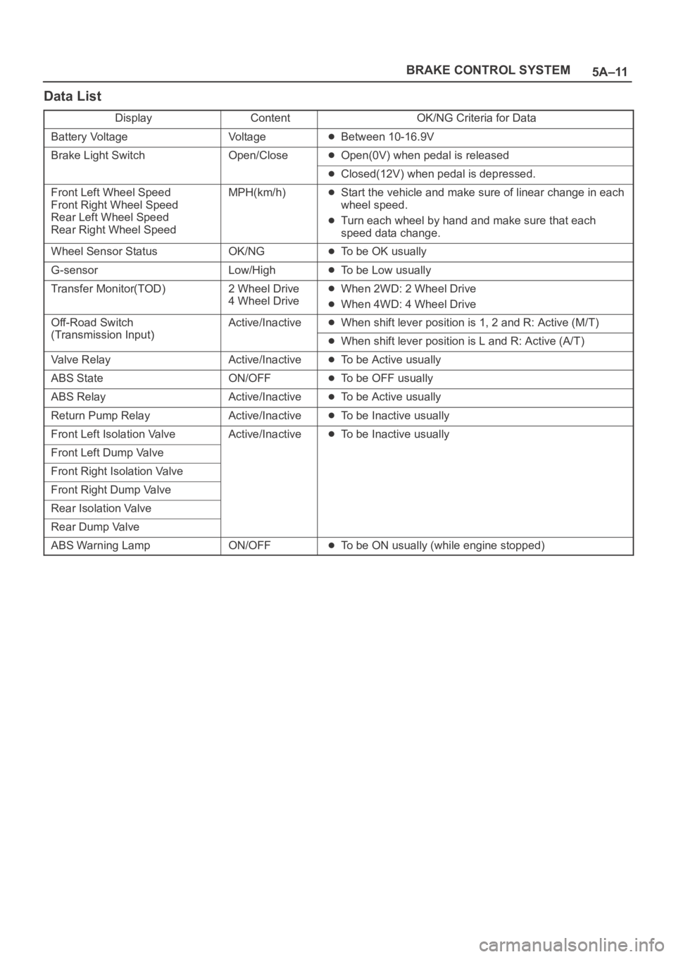
Data List
DisplayContentOK/NG Criteria for Data
Battery VoltageVo l t a g eBetween 10-16.9V
Brake Light SwitchOpen/CloseOpen(0V) when pedal is released
Closed(12V) when pedal is depressed.
Front Left Wheel Speed
Front Right Wheel Speed
Rear Left Wheel Speed
Rear Right Wheel SpeedMPH(km/h)Start the vehicle and make sure of linear change in each
wheel speed.
Turn each wheel by hand and make sure that each
speed data change.
Wheel Sensor StatusOK/NGTo be OK usually
G-sensorLow/HighTo be Low usually
Transfer Monitor(TOD)2 Wheel Drive
4 Wheel DriveWhen 2WD: 2 Wheel Drive
When 4WD: 4 Wheel Drive
Off-Road Switch
(Transmission Input)
Active/InactiveWhen shift lever position is 1, 2 and R: Active (M/T)
(Transmission Input)When shift lever position is L and R: Active (A/T)
Valve RelayActive/InactiveTo be Active usually
ABS StateON/OFFTo be OFF usually
ABS RelayActive/InactiveTo be Active usually
Return Pump RelayActive/InactiveTo be Inactive usually
Front Left Isolation ValveActive/InactiveTo be Inactive usually
Front Left Dump Valve
Front Right Isolation Valve
Front Right Dump Valve
Rear Isolation Valve
Rear Dump Valve
ABS Warning LampON/OFFTo be ON usually (while engine stopped)
Page 830 of 6000
5A–20
BRAKE CONTROL SYSTEM
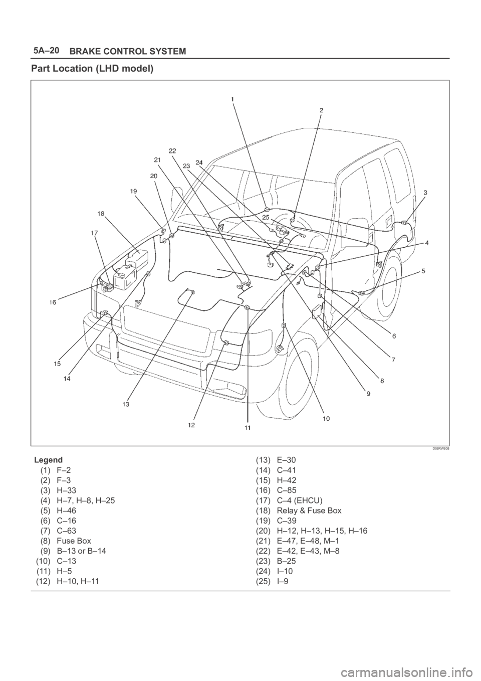
Part Location (LHD model)
D08RW808
Legend
(1) F–2
(2) F–3
(3) H–33
(4) H–7, H–8, H–25
(5) H–46
(6) C–16
(7) C–63
(8) Fuse Box
(9) B–13 or B–14
(10) C–13
(11) H–5
(12) H–10, H–11(13) E–30
(14) C–41
(15) H–42
(16) C–85
(17) C–4 (EHCU)
(18) Relay & Fuse Box
(19) C–39
(20) H–12, H–13, H–15, H–16
(21) E–47, E–48, M–1
(22) E–42, E–43, M–8
(23) B–25
(24) I–10
(25) I–9
Page 844 of 6000
5A–34
BRAKE CONTROL SYSTEM
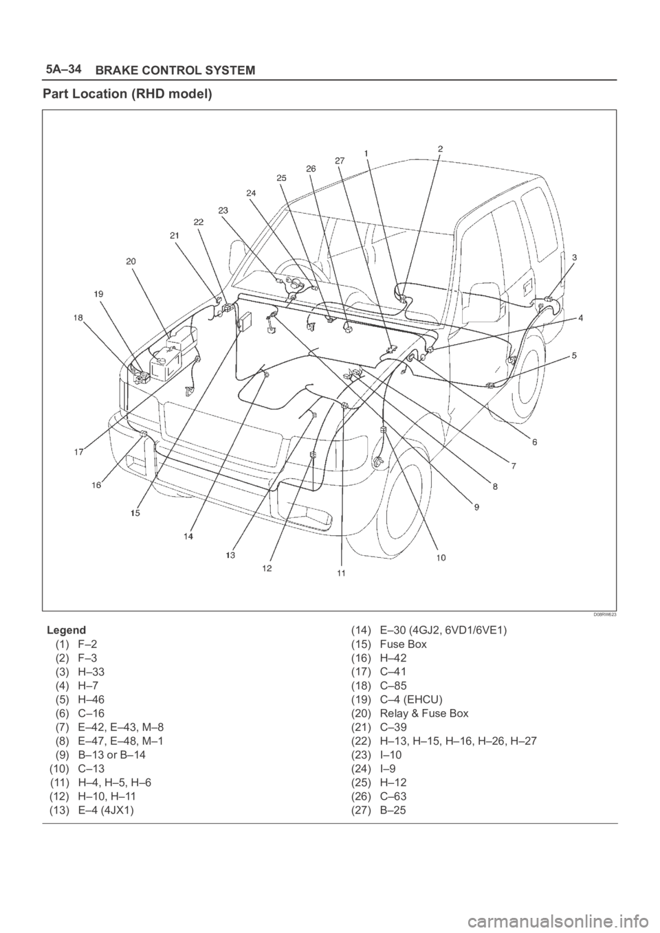
Part Location (RHD model)
D08RW623
Legend
(1) F–2
(2) F–3
(3) H–33
(4) H–7
(5) H–46
(6) C–16
(7) E–42, E–43, M–8
(8) E–47, E–48, M–1
(9) B–13 or B–14
(10) C–13
(11) H–4, H–5, H–6
(12) H–10, H–11
(13) E–4 (4JX1)(14) E–30 (4GJ2, 6VD1/6VE1)
(15) Fuse Box
(16) H–42
(17) C–41
(18) C–85
(19) C–4 (EHCU)
(20) Relay & Fuse Box
(21) C–39
(22) H–13, H–15, H–16, H–26, H–27
(23) I–10
(24) I–9
(25) H–12
(26) C–63
(27) B–25
Page 849 of 6000
5A–39 BRAKE CONTROL SYSTEM
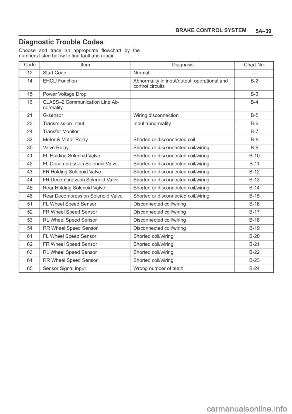
Diagnostic Trouble Codes
Choose and trace an appropriate flowchart by the
numbers listed below to find fault and repair.
Code
ItemDiagnosisChart No.
12Start CodeNormal—
14EHCU FunctionAbnormality in input/output, operational and
control circuitsB-2
15Power Voltage DropB-3
16CLASS–2 Communication Line Ab-
normalityB-4
21G-sensorWiring disconnectionB-5
23Transmission InputInput abnormalityB-6
24Transfer MonitorB-7
32Motor & Motor RelayShorted or disconnected coilB-8
35Valve RelayShorted or disconnected coil/wiringB-9
41FL Holding Solenoid ValveShorted or disconnected coil/wiringB-10
42FL Decompression Solenoid ValveShorted or disconnected coil/wiringB-11
43FR Holding Solenoid ValveShorted or disconnected coil/wiringB-12
44FR Decompression Solenoid ValveShorted or disconnected coil/wiringB-13
45Rear Holding Solenoid ValveShorted or disconnected coil/wiringB-14
46Rear Decompression Solenoid ValveShorted or disconnected coil/wiringB-15
51FL Wheel Speed SensorDisconnected coil/wiringB-16
52FR Wheel Speed SensorDisconnected coil/wiringB-17
53RL Wheel Speed SensorDisconnected coil/wiringB-18
54RR Wheel Speed SensorDisconnected coil/wiringB-19
61FL Wheel Speed SensorShorted coil/wiringB-20
62FR Wheel Speed SensorShorted coil/wiringB-21
63RL Wheel Speed SensorShorted coil/wiringB-22
64RR Wheel Speed SensorShorted coil/wiringB-23
65Sensor Signal InputWrong number of teethB-24
Page 857 of 6000
5A–47 BRAKE CONTROL SYSTEM
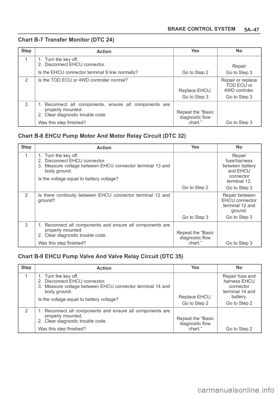
Chart B-7 Transfer Monitor (DTC 24)
StepActionYe sNo
11. Turn the key off.
2. Disconnect EHCU connector.
Is the EHCU connector terminal 9 line normally?
Go to Step 2
Repair
Go to Step 3
2Is the TOD ECU or 4WD controller normal?
Replace EHCU.
Go to Step 3
Repair or replace
TOD ECU or
4WD contrder.
Go to Step 3
31. Reconnect all components, ensure all components are
properly mounted.
2. Clear diagnostic trouble code.
Was this step finished?
Repeat the “Basic
diagnostic flow
chart.”
Go to Step 3
Chart B-8 EHCU Pump Motor And Motor Relay Circuit (DTC 32)
StepActionYe sNo
11. Turn the key off.
2. Disconnect EHCU connector.
3. Measure voltage between EHCU connector terminal 13 and
body ground.
Is the voltage equal to battery voltage?
Go to Step 2
Repair
fuse/harness
between battery
and EHCU
connector
terminal 13.
Go to Step 3
2Is there continuity between EHCU connector terminal 12 and
ground?
Go to Step 3
Repair between
EHCU connector
terminal 12 and
ground.
Go to Step 3
31. Reconnect all components and ensure all components are
properly mounted.
2. Clear diagnostic trouble code.
Was this step finished?
Repeat the “Basic
diagnostic flow
chart.”
Go to Step 3
Chart B-9 EHCU Pump Valve And Valve Relay Circuit (DTC 35)
StepActionYe sNo
11. Turn the key off.
2. Disconnect EHCU connector.
3. Measure voltage between EHCU connector terminal 14 and
body ground.
Is the voltage equal to battery voltage?
Replace EHCU.
Go to Step 2
Repair fuse and
harness EHCU
connector
terminal 14 and
battery.
Go to Step 2
21. Reconnect all components and ensure all components are
properly mounted.
2. Clear diagnostic trouble code.
Was this step finished?
Repeat the “Basic
diagnostic flow
chart.”
Go to Step 2
Page 961 of 6000
6A–5
ENGINE MECHANICAL
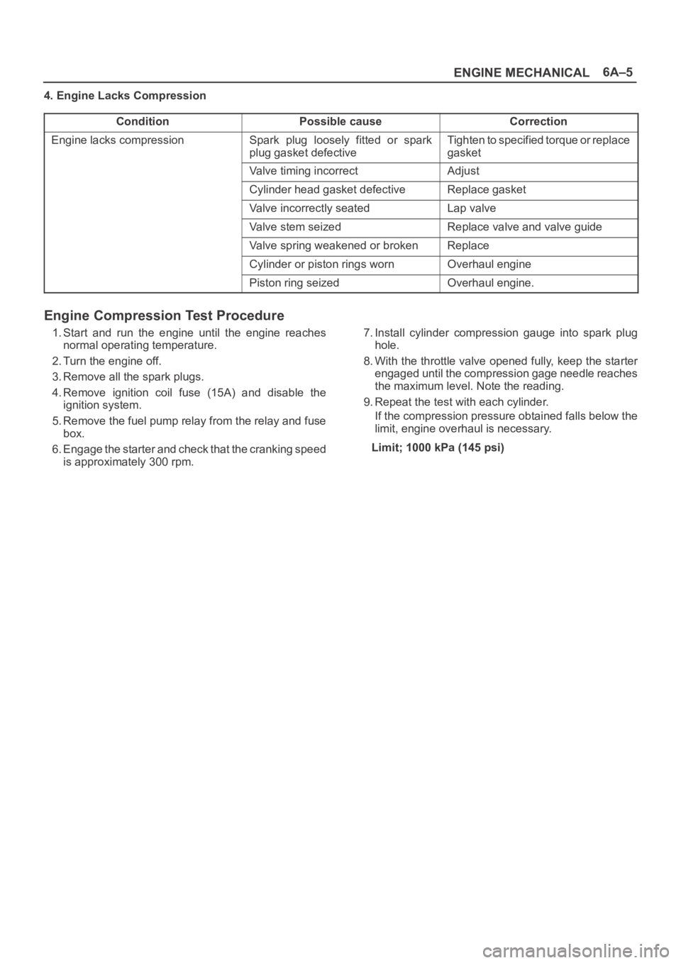
4. Engine Lacks Compression
Condition
Possible causeCorrection
Engine lacks compressionSpark plug loosely fitted or spark
plug gasket defectiveTighten to specified torque or replace
gasket
Valve timing incorrectAdjust
Cylinder head gasket defectiveReplace gasket
Valve incorrectly seatedLap valve
Valve stem seizedReplace valve and valve guide
Valve spring weakened or brokenReplace
Cylinder or piston rings wornOverhaul engine
Piston ring seizedOverhaul engine.
Engine Compression Test Procedure
1. Start and run the engine until the engine reaches
normal operating temperature.
2. Turn the engine off.
3. Remove all the spark plugs.
4. Remove ignition coil fuse (15A) and disable the
ignition system.
5. Remove the fuel pump relay from the relay and fuse
box.
6. Engage the starter and check that the cranking speed
is approximately 300 rpm.7. Install cylinder compression gauge into spark plug
hole.
8. With the throttle valve opened fully, keep the starter
engaged until the compression gage needle reaches
the maximum level. Note the reading.
9. Repeat the test with each cylinder.
If the compression pressure obtained falls below the
limit, engine overhaul is necessary.
Limit; 1000 kPa (145 psi)
Page 962 of 6000
6A–6
ENGINE MECHANICAL
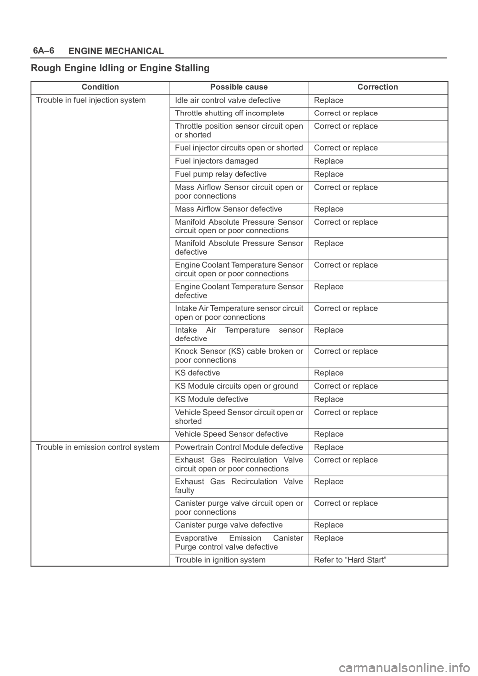
Rough Engine Idling or Engine Stalling
ConditionPossible causeCorrection
Trouble in fuel injection systemIdle air control valve defectiveReplace
Throttle shutting off incompleteCorrect or replace
Throttle position sensor circuit open
or shortedCorrect or replace
Fuel injector circuits open or shortedCorrect or replace
Fuel injectors damagedReplace
Fuel pump relay defectiveReplace
Mass Airflow Sensor circuit open or
poor connectionsCorrect or replace
Mass Airflow Sensor defectiveReplace
Manifold Absolute Pressure Sensor
circuit open or poor connectionsCorrect or replace
Manifold Absolute Pressure Sensor
defectiveReplace
Engine Coolant Temperature Sensor
circuit open or poor connectionsCorrect or replace
Engine Coolant Temperature Sensor
defectiveReplace
Intake Air Temperature sensor circuit
open or poor connectionsCorrect or replace
Intake Air Temperature sensor
defectiveReplace
Knock Sensor (KS) cable broken or
poor connectionsCorrect or replace
KS defectiveReplace
KS Module circuits open or groundCorrect or replace
KS Module defectiveReplace
Vehicle Speed Sensor circuit open or
shortedCorrect or replace
Vehicle Speed Sensor defectiveReplace
Trouble in emission control systemPowertrain Control Module defectiveReplace
Exhaust Gas Recirculation Valve
circuit open or poor connectionsCorrect or replace
Exhaust Gas Recirculation Valve
faultyReplace
Canister purge valve circuit open or
poor connectionsCorrect or replace
Canister purge valve defectiveReplace
Evaporative Emission Canister
Purge control valve defectiveReplace
Trouble in ignition systemRefer to “Hard Start”
Page 969 of 6000
6A–13
ENGINE MECHANICAL
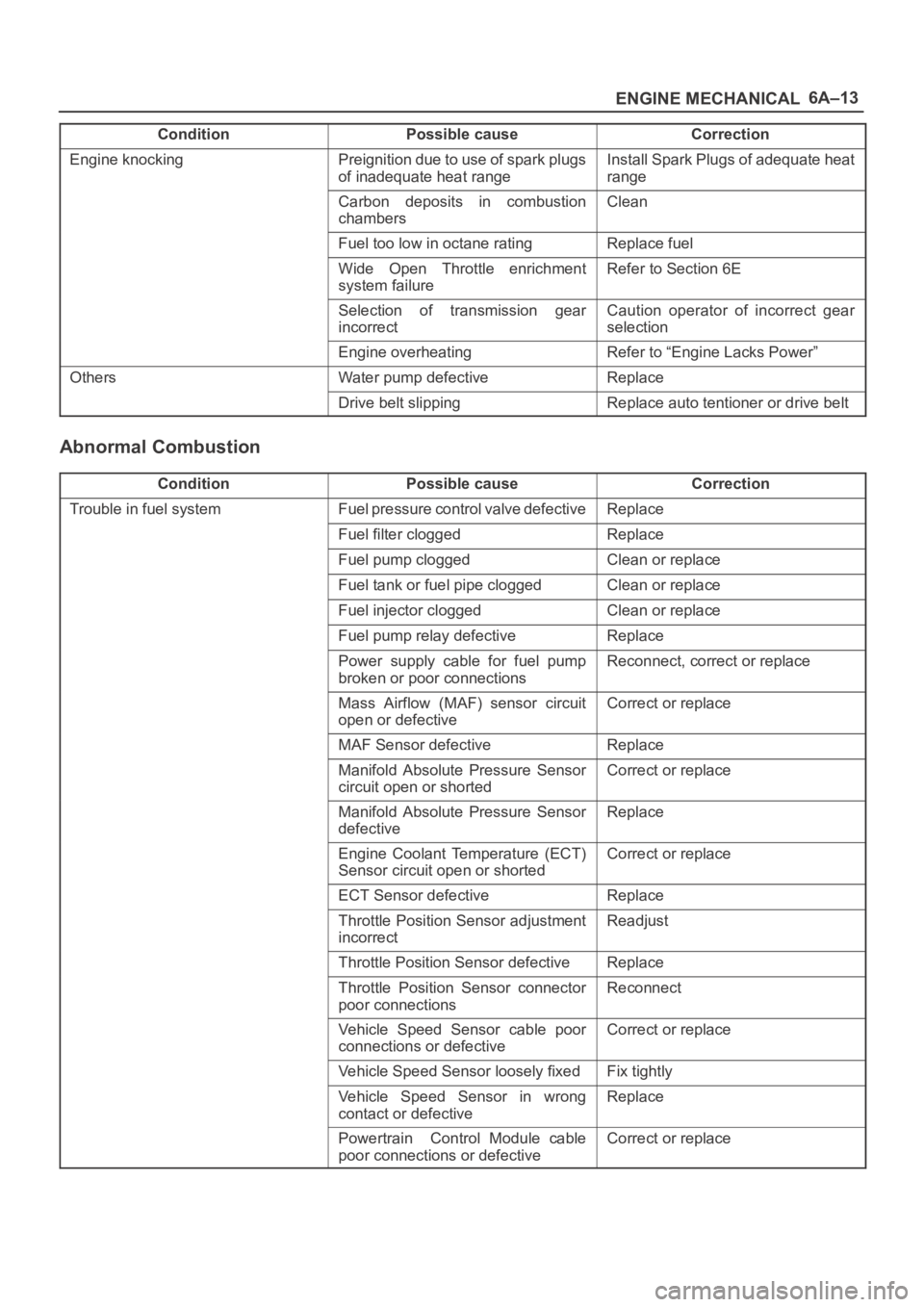
Condition CorrectionPossible cause
Engine knockingPreignition due to use of spark plugs
of inadequate heat rangeInstall Spark Plugs of adequate heat
range
Carbon deposits in combustion
chambersClean
Fuel too low in octane ratingReplace fuel
Wide Open Throttle enrichment
system failureRefer to Section 6E
Selection of transmission gear
incorrectCaution operator of incorrect gear
selection
Engine overheatingRefer to “Engine Lacks Power”
OthersWater pump defectiveReplace
Drive belt slippingReplace auto tentioner or drive belt
Abnormal Combustion
ConditionPossible causeCorrection
Trouble in fuel systemFuel pressure control valve defectiveReplace
Fuel filter cloggedReplace
Fuel pump cloggedClean or replace
Fuel tank or fuel pipe cloggedClean or replace
Fuel injector cloggedClean or replace
Fuel pump relay defectiveReplace
Power supply cable for fuel pump
broken or poor connectionsReconnect, correct or replace
Mass Airflow (MAF) sensor circuit
open or defectiveCorrect or replace
MAF Sensor defectiveReplace
Manifold Absolute Pressure Sensor
circuit open or shortedCorrect or replace
Manifold Absolute Pressure Sensor
defectiveReplace
Engine Coolant Temperature (ECT)
Sensor circuit open or shortedCorrect or replace
ECT Sensor defectiveReplace
Throttle Position Sensor adjustment
incorrectReadjust
Throttle Position Sensor defectiveReplace
Throttle Position Sensor connector
poor connectionsReconnect
Vehicle Speed Sensor cable poor
connections or defectiveCorrect or replace
Vehicle Speed Sensor loosely fixedFix tightly
Vehicle Speed Sensor in wrong
contact or defectiveReplace
Powertrain Control Module cable
poor connections or defectiveCorrect or replace
Page 1068 of 6000
6C–1
ENGINE FUEL
ENGINE
ENGINE FUEL
CONTENTS
Service Precaution 6C–1. . . . . . . . . . . . . . . . . . . . . .
General Description 6C–2. . . . . . . . . . . . . . . . . . . . .
Fuel Metering 6C–3. . . . . . . . . . . . . . . . . . . . . . . . . . .
Fuel Filter 6C–4. . . . . . . . . . . . . . . . . . . . . . . . . . . . . .
Fuel Filter and Associated Parts 6C–4. . . . . . . . .
Removal 6C–4. . . . . . . . . . . . . . . . . . . . . . . . . . . . .
Inspection 6C–4. . . . . . . . . . . . . . . . . . . . . . . . . . . .
Installation 6C–5. . . . . . . . . . . . . . . . . . . . . . . . . . . .
Inspection 6C–5. . . . . . . . . . . . . . . . . . . . . . . . . . . .
In–Tank Fuel Filter 6C–5. . . . . . . . . . . . . . . . . . . . .
Fuel Pump Flow Test 6C–5. . . . . . . . . . . . . . . . . . .
Fuel Pump 6C–6. . . . . . . . . . . . . . . . . . . . . . . . . . . . .
Fuel Pump and Associated Parts 6C–6. . . . . . . .
Removal 6C–6. . . . . . . . . . . . . . . . . . . . . . . . . . . . .
Installation 6C–6. . . . . . . . . . . . . . . . . . . . . . . . . . . .
Fuel Pump Relay 6C–7. . . . . . . . . . . . . . . . . . . . . . . .
General Description 6C–7. . . . . . . . . . . . . . . . . . . . .
Fuel Tank 6C–7. . . . . . . . . . . . . . . . . . . . . . . . . . . . . . Fuel Tank and Associated Parts 6C–7. . . . . . . . .
Removal 6C–7. . . . . . . . . . . . . . . . . . . . . . . . . . . . .
Installation 6C–8. . . . . . . . . . . . . . . . . . . . . . . . . . . .
Fuel Tube / Quick – Connect Fittings 6C–8. . . . . . .
Precautions 6C–8. . . . . . . . . . . . . . . . . . . . . . . . . . .
Cautions During Work 6C–8. . . . . . . . . . . . . . . . . .
Removal 6C–8. . . . . . . . . . . . . . . . . . . . . . . . . . . . .
Reuse of Quick–Connector 6C–10. . . . . . . . . . . . . . .
Assembling Advice 6C–10. . . . . . . . . . . . . . . . . . . . . .
Fuel Gauge Unit 6C–11. . . . . . . . . . . . . . . . . . . . . . . .
Fuel Gauge Unit and Associated Parts 6C–11. . .
Removal 6C–11. . . . . . . . . . . . . . . . . . . . . . . . . . . . .
Installation 6C–11. . . . . . . . . . . . . . . . . . . . . . . . . . . .
Fuel Filler Cap 6C–12. . . . . . . . . . . . . . . . . . . . . . . . . .
General Description 6C–12. . . . . . . . . . . . . . . . . . . . .
Inspection 6C–12. . . . . . . . . . . . . . . . . . . . . . . . . . . .
Main Data and Specifications 6C–12. . . . . . . . . . . . .
Service Precaution
WARNING: IF SO EQUIPPED WITH A
SUPPLEMENTAL RESTRAINT SYSTEM (SRS),
REFER TO THE SRS COMPONENT AND WIRING
LOCATION VIEW IN ORDER TO DETERMINE
WHETHER YOU ARE PERFORMING SERVICE ON OR
NEAR THE SRS COMPONENTS OR THE SRS
WIRING. WHEN YOU ARE PERFORMING SERVICE
ON OR NEAR THE SRS COMPONENTS OR THE SRS
WIRING, REFER TO THE SRS SERVICE
INFORMATION. FAILURE TO FOLLOW WARNINGS
COULD RESULT IN POSSIBLE AIR BAG
DEPLOYMENT, PERSONAL INJURY, OR
OTHERWISE UNNEEDED SRS SYSTEM REPAIRS.
CAUTION: Always use the correct fastener in the
proper location. When you replace a fastener, use
ONLY the exact part number for that application.
ISUZU will call out those fasteners that require a
replacement after removal. ISUZU will also call out
the fasteners that require thread lockers or thread
sealant. UNLESS OTHERWISE SPECIFIED, do not
use supplemental coatings (Paints, greases, or other
corrosion inhibitors) on threaded fasteners or
fastener joint interfaces. Generally, such coatings
adversely affect the fastener torque and the joint
clamping force, and may damage the fastener. When
you install fasteners, use the correct tightening
sequence and specifications. Following these
instructions can help you avoid damage to parts and
systems.
Page 1072 of 6000
6C–5
ENGINE FUEL
Installation
1. Install the fuel filter in the proper direction.
2. Install fuel filter holder fixing bolt.
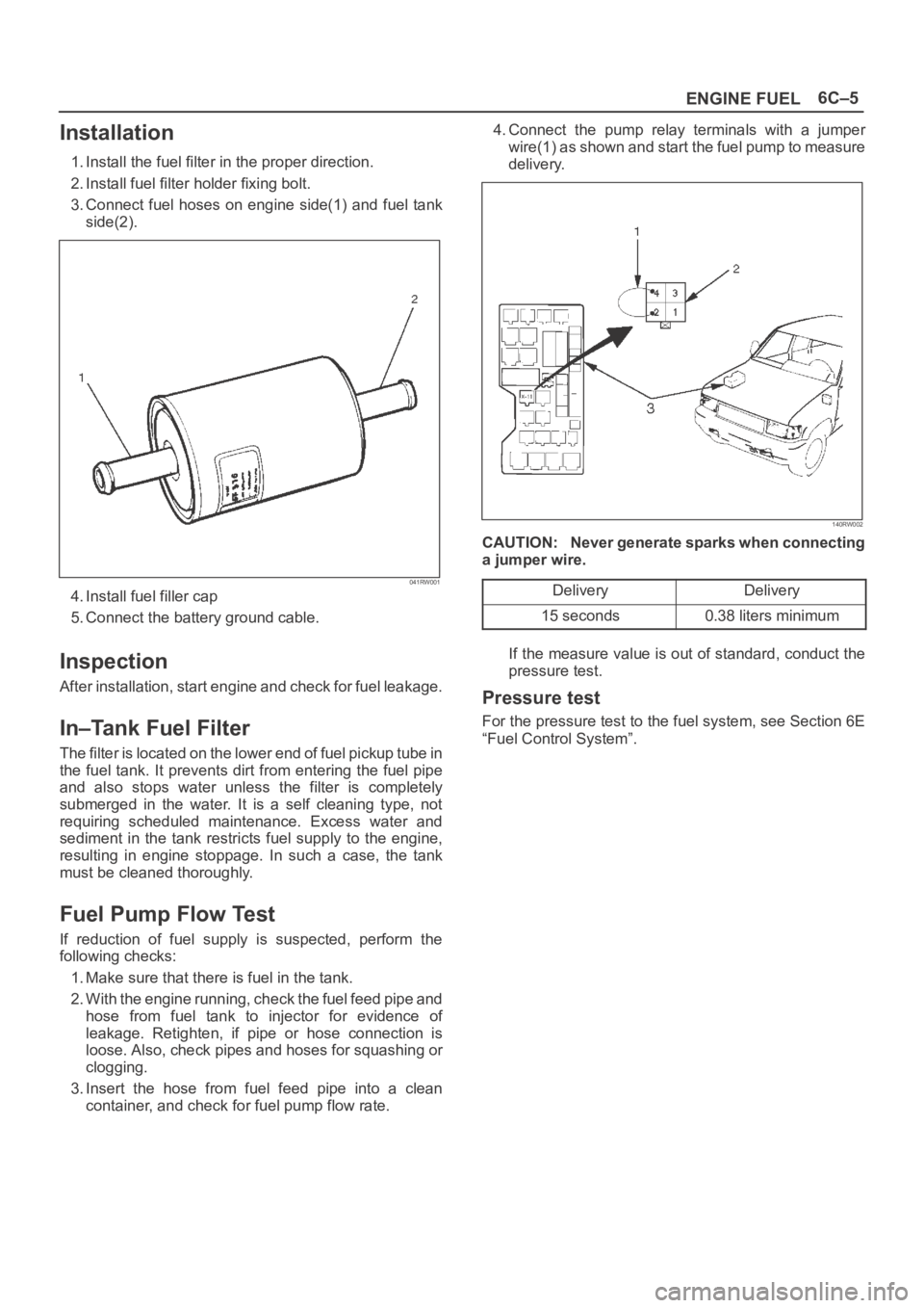
3. Connect fuel hoses on engine side(1) and fuel tank
side(2).
041RW001
4. Install fuel filler cap
5. Connect the battery ground cable.
Inspection
After installation, start engine and check for fuel leakage.
In–Tank Fuel Filter
The filter is located on the lower end of fuel pickup tube in
the fuel tank. It prevents dirt from entering the fuel pipe
and also stops water unless the filter is completely
submerged in the water. It is a self cleaning type, not
requiring scheduled maintenance. Excess water and
sediment in the tank restricts fuel supply to the engine,
resulting in engine stoppage. In such a case, the tank
must be cleaned thoroughly.
Fuel Pump Flow Test
If reduction of fuel supply is suspected, perform the
following checks:
1. Make sure that there is fuel in the tank.
2. With the engine running, check the fuel feed pipe and
hose from fuel tank to injector for evidence of
leakage. Retighten, if pipe or hose connection is
loose. Also, check pipes and hoses for squashing or
clogging.
3. Insert the hose from fuel feed pipe into a clean
container, and check for fuel pump flow rate.4. Connect the pump relay terminals with a jumper
wire(1) as shown and start the fuel pump to measure
delivery.
140RW002
CAUTION: Never generate sparks when connecting
a jumper wire.
Delivery
Delivery
15 seconds0.38 liters minimum
If the measure value is out of standard, conduct the
pressure test.
Pressure test
For the pressure test to the fuel system, see Section 6E
“Fuel Control System”.