Differential oil OPEL FRONTERA 1998 Service Manual
[x] Cancel search | Manufacturer: OPEL, Model Year: 1998, Model line: FRONTERA, Model: OPEL FRONTERA 1998Pages: 6000, PDF Size: 97 MB
Page 524 of 6000
DIFFERENTIAL (REAR 244mm)
4A2B–21
Disassembly
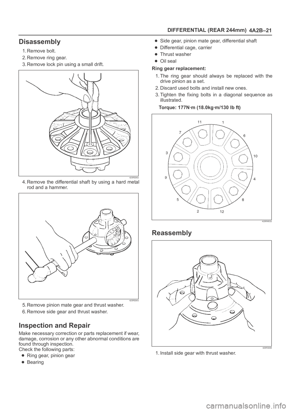
1. Remove bolt.
2. Remove ring gear.
3. Remove lock pin using a small drift.
425RS042
4. Remove the differential shaft by using a hard metal
rod and a hammer.
425RS043
5. Remove pinion mate gear and thrust washer.
6. Remove side gear and thrust washer.
Inspection and Repair
Make necessary correction or parts replacement if wear,
damage, corrosion or any other abnormal conditions are
found through inspection.
Check the following parts:
Ring gear, pinion gear
Bearing
Side gear, pinion mate gear, differential shaft
Differential cage, carrier
Thrust washer
Oil seal
Ring gear replacement:
1. The ring gear should always be replaced with the
drive pinion as a set.
2. Discard used bolts and install new ones.
3. Tighten the fixing bolts in a diagonal sequence as
illustrated.
Torque: 177Nꞏm (18.0kgꞏm/130 lb ft)
425RW033
Reassembly
425RS048
1. Install side gear with thrust washer.
Page 532 of 6000

DIFFERENTIAL (REAR 244mm)
4A2B–29
Special Tools
ILLUSTRATIONTOOL NO.
TOOL NAME
5–8840–2294–0
(J–39210)
Installer; Axle shaft inner
seal
5–8840–0133–0
(J–8614–01)
Pinion flange holder
5–8840–2165–0
(J–37263)
Installer; Pinion oil seal
5–8840–2029–0
(J–42832)
Holding fixture
5–8840–0003–0
(J–3289–20)
Holding fixture base
5–8840–2587–0
(J–42379)
Remover; Bearing
ILLUSTRATIONTOOL NO.
TOOL NAME
5–8840–2576–0
(J–8107–3)
Adapter; Side bearing
plug
5–8840–0008–0
(J–8611–01)
Installer; Outer bearing
outer race
5–8840–0007–0
(J–8092)
Grip
5–8840–2571–0
(J–42831)
Installer; Inner bearing
outer race
5–8840–2575–0
(J–42824)
Pilot;Outer
5–8840–0127–0
(J–21777–43)
Nut & Stud
Page 659 of 6000
DRIVE LINE CONTROL SYSTEM (TOD) 4B2–88
StepActionYe sNo
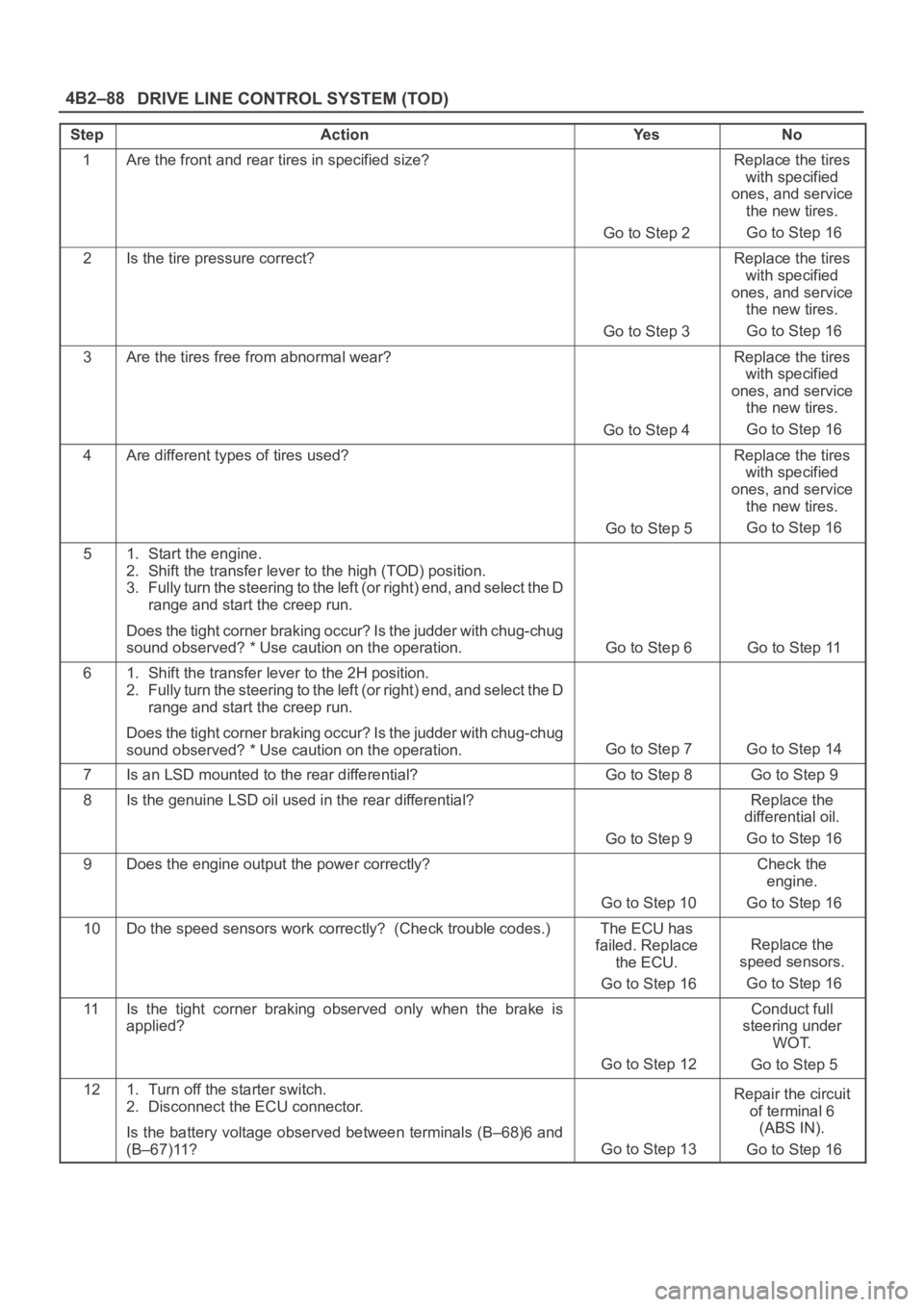
1Are the front and rear tires in specified size?
Go to Step 2
Replace the tires
with specified
ones, and service
the new tires.
Go to Step 16
2Is the tire pressure correct?
Go to Step 3
Replace the tires
with specified
ones, and service
the new tires.
Go to Step 16
3Are the tires free from abnormal wear?
Go to Step 4
Replace the tires
with specified
ones, and service
the new tires.
Go to Step 16
4Are different types of tires used?
Go to Step 5
Replace the tires
with specified
ones, and service
the new tires.
Go to Step 16
51. Start the engine.
2. Shift the transfer lever to the high (TOD) position.
3. Fully turn the steering to the left (or right) end, and select the D
range and start the creep run.
Does the tight corner braking occur? Is the judder with chug-chug
sound observed? * Use caution on the operation.
Go to Step 6 Go to Step 11
61. Shift the transfer lever to the 2H position.
2. Fully turn the steering to the left (or right) end, and select the D
range and start the creep run.
Does the tight corner braking occur? Is the judder with chug-chug
sound observed? * Use caution on the operation.
Go to Step 7 Go to Step 14
7Is an LSD mounted to the rear differential? Go to Step 8 Go to Step 9
8Is the genuine LSD oil used in the rear differential?
Go to Step 9
Replace the
differential oil.
Go to Step 16
9Does the engine output the power correctly?
Go to Step 10
Check the
engine.
Go to Step 16
10Do the speed sensors work correctly? (Check trouble codes.)The ECU has
failed. Replace
the ECU.
Go to Step 16
Replace the
speed sensors.
Go to Step 16
11Is the tight corner braking observed only when the brake is
applied?
Go to Step 12
Conduct full
steering under
WOT.
Go to Step 5
121. Turn off the starter switch.
2. Disconnect the ECU connector.
Is the battery voltage observed between terminals (B–68)6 and
(B–67)11?
Go to Step 13
Repair the circuit
of terminal 6
(ABS IN).
Go to Step 16
Page 669 of 6000
4C–3 DRIVE SHAFT SYSTEM
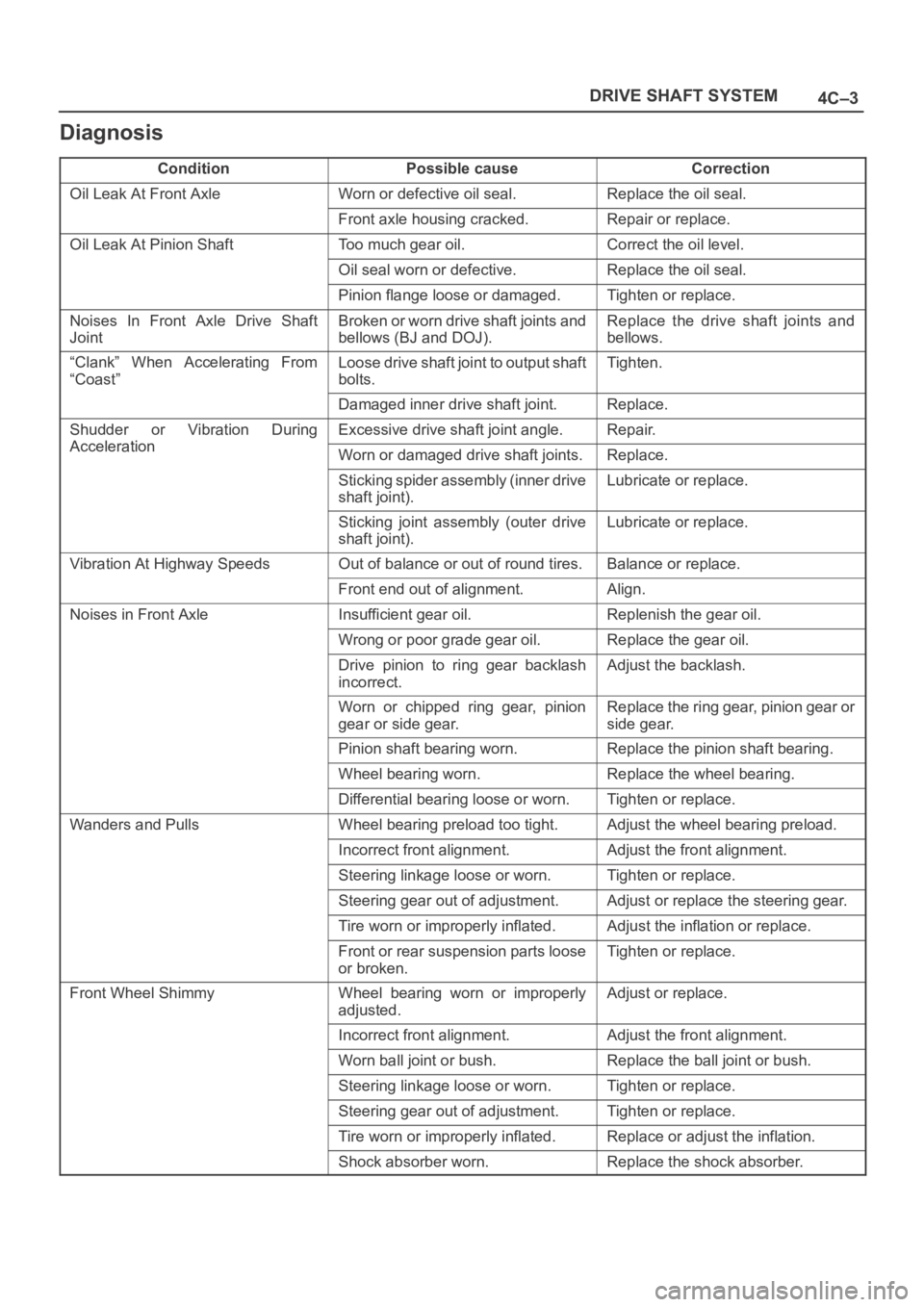
Diagnosis
ConditionPossible causeCorrection
Oil Leak At Front AxleWorn or defective oil seal.Replace the oil seal.
Front axle housing cracked.Repair or replace.
Oil Leak At Pinion ShaftToo much gear oil.Correct the oil level.
Oil seal worn or defective.Replace the oil seal.
Pinion flange loose or damaged.Tighten or replace.
Noises In Front Axle Drive Shaft
JointBroken or worn drive shaft joints and
bellows (BJ and DOJ).Replace the drive shaft joints and
bellows.
“Clank” When Accelerating From
“Coast”Loose drive shaft joint to output shaft
bolts.Tighten.
Damaged inner drive shaft joint.Replace.
Shudder or Vibration During
Acceleration
Excessive drive shaft joint angle.Repair.
AccelerationWorn or damaged drive shaft joints.Replace.
Sticking spider assembly (inner drive
shaft joint).Lubricate or replace.
Sticking joint assembly (outer drive
shaft joint).Lubricate or replace.
Vibration At Highway SpeedsOut of balance or out of round tires.Balance or replace.
Front end out of alignment.Align.
Noises in Front AxleInsufficient gear oil.Replenish the gear oil.
Wrong or poor grade gear oil.Replace the gear oil.
Drive pinion to ring gear backlash
incorrect.Adjust the backlash.
Worn or chipped ring gear, pinion
gear or side gear.Replace the ring gear, pinion gear or
side gear.
Pinion shaft bearing worn.Replace the pinion shaft bearing.
Wheel bearing worn.Replace the wheel bearing.
Differential bearing loose or worn.Tighten or replace.
Wanders and PullsWheel bearing preload too tight.Adjust the wheel bearing preload.
Incorrect front alignment.Adjust the front alignment.
Steering linkage loose or worn.Tighten or replace.
Steering gear out of adjustment.Adjust or replace the steering gear.
Tire worn or improperly inflated.Adjust the inflation or replace.
Front or rear suspension parts loose
or broken.Tighten or replace.
Front Wheel ShimmyWheel bearing worn or improperly
adjusted.Adjust or replace.
Incorrect front alignment.Adjust the front alignment.
Worn ball joint or bush.Replace the ball joint or bush.
Steering linkage loose or worn.Tighten or replace.
Steering gear out of adjustment.Tighten or replace.
Tire worn or improperly inflated.Replace or adjust the inflation.
Shock absorber worn.Replace the shock absorber.
Page 689 of 6000
4C–23 DRIVE SHAFT SYSTEM
Front Axle Drive Shaft
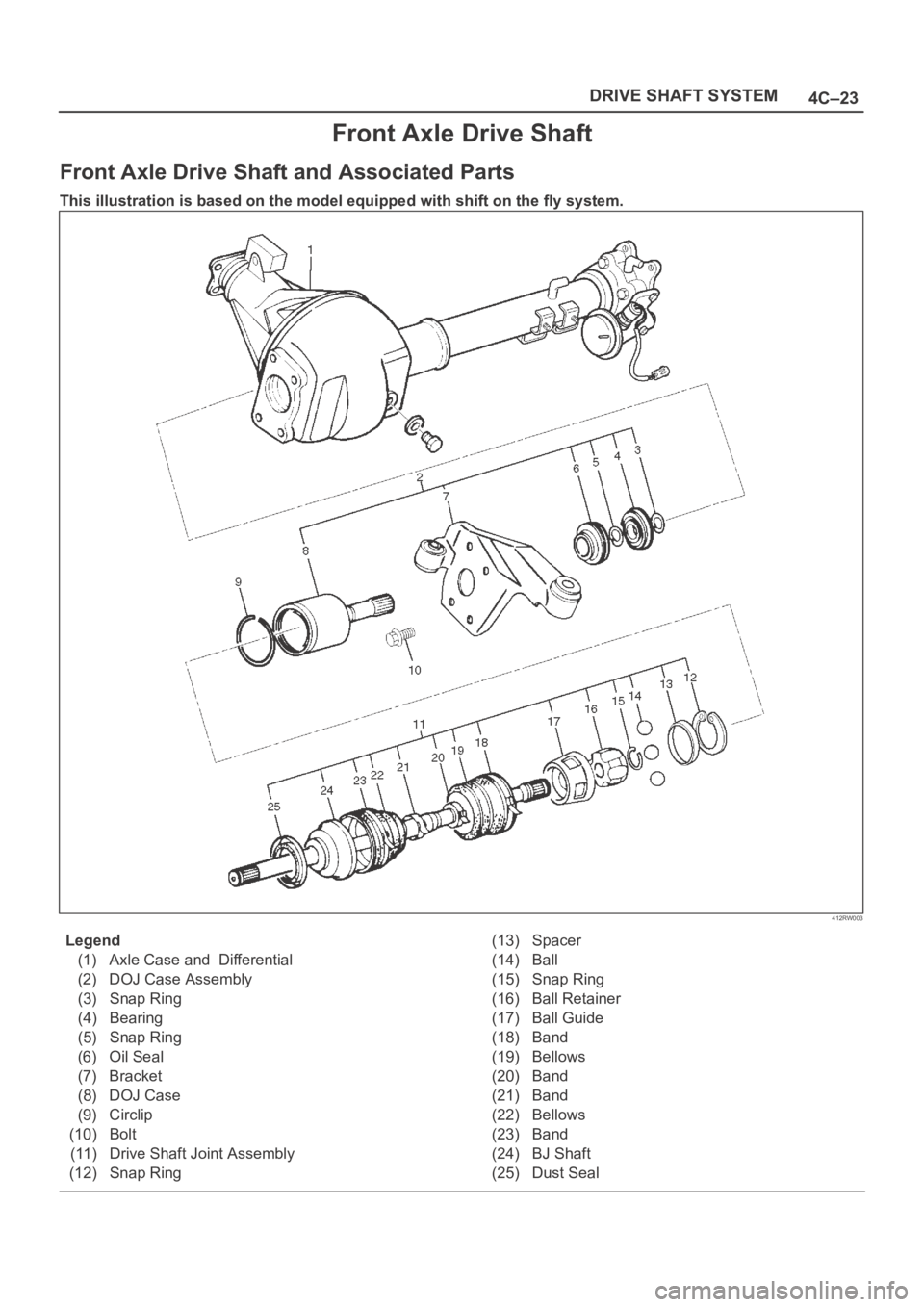
Front Axle Drive Shaft and Associated Parts
This illustration is based on the model equipped with shift on the fly system.
412RW003
Legend
(1) Axle Case and Differential
(2) DOJ Case Assembly
(3) Snap Ring
(4) Bearing
(5) Snap Ring
(6) Oil Seal
(7) Bracket
(8) DOJ Case
(9) Circlip
(10) Bolt
(11) Drive Shaft Joint Assembly
(12) Snap Ring(13) Spacer
(14) Ball
(15) Snap Ring
(16) Ball Retainer
(17) Ball Guide
(18) Band
(19) Bellows
(20) Band
(21) Band
(22) Bellows
(23) Band
(24) BJ Shaft
(25) Dust Seal
Page 699 of 6000

4C–33 DRIVE SHAFT SYSTEM
412RS037
Reassembly
1. Install the new oil seal which has been immersed in
differential gear oil, by using an oil seal installer
5–8840–2407–0 and grip 5–8840–0007–0.
412RS043
2. Force a new needle bearing into inner shaft by using a
installer 5–8840–2408–0 and grip 5–8840–0007–0.
412RS051
3. Place a new snap ring(internal) in inner shaft.
Force a new inner shaft bearing into the inner shaft by
using a installer 5–8840–2197–0 and press.
412RS044
4. Install snap ring(external).
NOTE: Be careful not to damage the inner shaft.
5. Clean the housing contact surface of the front axle
case and insert inner shaft assembly into the front
axle case.
Page 700 of 6000

4C–34
DRIVE SHAFT SYSTEM
NOTE: Be careful not to damage seal.
6. Install snap ring (internal) in the groove of front axle
case.
NOTE: Be sure to install the snap ring properly.
412RW017
7. Apply differential gear oil to clutch gear, then install
clutch gear.
8. Apply differential gear oil to sleeve, then install
sleeve.
9. Clean contact surface with the front axle and actuator
mounting surface. Apply liquid gasket to the contact
surface on the front axle case, then install in the
housing.
412RW023
10. Tighten bolts to specified torque.
Torque: 116Nꞏm (11.8 kgꞏm/85 lb ft)11. Clean the actuator contact surface with the housing
then Install and tighten shift position switch to
specified torque.
Torque: 39Nꞏm (4.0 kgꞏm/29 lb ft)
12. Apply liquid gasket to the contact surface on the
actuator side.
412RW012
13. Align shift arm with the groove of sleeve and install the
actuator.
14. Tighten bolts to specified torque.
Torque: 13Nꞏm (1.3 kgꞏm/113 lb in)
15. Install front axle drive shaft and mounting bracket.
Tighten fitting bolts to specified torque.
Torque: 116Nꞏm (11.8 kgꞏm/85 lb ft)
16. Pour specified amount of differential gear oil to filler
plug.
Front Differential
Oil Capacity: 1.4lit (1.23 Imp qt/1.48 US qt)
Actuator Housing
Oil Capacity: 0.12lit (0.10 Imp qt/0.13 US qt)
17. Install filler plug through gasket and tighten to
specified torque.
To r q u e : 7 8 N ꞏm ( 5 8 l b f t )
Page 701 of 6000

4C–35 DRIVE SHAFT SYSTEM
Main Data and Specifications
General Specifications
Front drive axle oil capacity1.4 liter (1.23 Imp qt/1.48 US qt)(Differential)
0.12 liter (0.10 Imp qt/0.13 US qt)(Actuator Housing:Shift on the fly)
Type of lubricantGL–5 (Multi grade type) Refer to chart in General Information
Axle shaft typeConstant velocity joint(Birfield joint type and double offset joint)
Torque Specifications
E04RW020
Page 1070 of 6000
6C–3
ENGINE FUEL
Adhere to all Notices and Cautions.
All gasoline engines are designed to use only unleaded
gasoline. Unleaded gasoline must be used for proper
emission control system operation.
Its use will also minimize spark plug fouling and extend
engine oil life. Using leaded gasoline can damage the
emission control system and could result in loss of
emission warranty coverage.
All cars are equipped with an Evaporative Emission
Control System. The purpose of the system is to minimize
the escape of fuel vapors to the atmosphere.
Fuel Metering
The Engine Control Module (ECM) is in complete control
of this fuel delivery system during normal driving
conditions.
The intake manifold function, like that of a diesel, is used
only to let air into the engine. The fuel is injected by
separate injectors that are mounted over the intake
manifold.
The Manifold Absolute Pressure (MAP) sensor measures
the changes in the intake manifold pressure which result
from engine load and speed changes, which the MAP
sensor converts to a voltage output.
This sensor generates the voltage to change
corresponding to the flow of the air drawn into the engine.
The changing voltage is transformed into an electric
signal and provided to the ECM.
With receipt of the signals sent from the MAP sensor,
Intake Air Temperature sensor and others, the ECM
determines an appropriate fuel injection pulse width
feeding such information to the fuel injector valves to
effect an appropriate air/fuel ratio.
The Multiport Fuel Injection system utilizes an injection
system where the injectors turn on at every crankshaft
re vol u tion . Th e EC M con tro ls t he in je cto r on tim e so t ha t
the correct amount of fuel is metered depending on
driving conditions.
Two interchangeable “O” rings are used on the injector
that must be replaced when the injectors are removed.
The fuel rail is attached to the top of the intake manifold
and supplies fuel to all the injectors.
Fuel is recirculated through the rail continually while the
engine is running. This removes air and vapors from the
fuel as well as keeping the fuel cool during hot weather
operation.
The fuel pressure control valve that is mounted on the fuel
rail maintains a pressure differential across the injectors
under all operating conditions. It is accomplished by
controlling the amount of fuel that is recirculated back to
the fuel tank based on engine demand.
See Section “Driveability and Emission” for more
information and diagnosis.
Page 3505 of 6000
RESTRAINT CONTROL SYSTEM 9J1–18
DTC 17 Passenger Deployment Loop Open
StepActionYe sNo
1Was the “SRS Diagnostic System Check” performed?
Go to Step 2
Go to the “SRS
Diagnostic
System Check”
21. When measurements are requested in this chart use
5–8840–0285–0 DVM with correct terminal adapter from
5–8840–0385–0.
2. Using scan tool data list function, read and record the
passenger differential voltage.
Is passenger VDIF 0.425 volts or more?
Go to Step 3Go to Chart A
31. Ignition switch “OFF”.
2. Make sure the passenger air bag assembly yellow 2–pin
connector located behind the glove box assembly is seated
properly.
Is the yellow 2–pin connector connected properly?
Go to Step 4
Seat passenger
air bag assembly
yellow 2–pin
connector
properly
Go to Step 7
41. Disconnect and inspect the passenger air bag assembly
yellow 2–pin connector located behind the glove box
assembly.
2. If ok, reconnect the passenger air bag assembly 2–pin
connector.
3. Ignition switch “ON”.
Is DTC 17 current?
Go to Step 5Go to Step 7
51. Ignition switch “Off.”
2. Disconnect SRS coil and passenger air bag assembly, yellow
2–pin connector located at the base of the steering column and
behind the glove box assembly.
3. Connect 5–8840–2421–0 SRS driver / passenger load tool
and appropriate adapters to SRS coil and passenger air bag
assembly harness connectors.
4. Ignition switch “ON.”
Is DTC 17 current?
Go to Step 6
Ignition switch
“Off”
Replace the
passenger air
bag assembly
Go to Step 7
61. Ignition switch “Off.”
2. There has been an open circuit resistance in the passenger
deployment loop.
3. Use the high resolution ohmmeter mode of the DVM while
checking IB07–YEL/GRN and IB08–YEL/RED, and SDM
connector terminal “15” and “16” to locate the root cause.
Was a fault found?
Replace SRS
harness
Go to Step 7
Go to Chart A
71. Reconnect all components ensure all component are properly
mounted.
2. Clear diagnostic trouble codes.
Was this step finished?
Go to the “SRS
Diagnostic
System Check”
Go to Step 7