Seat OPEL FRONTERA 1998 Manual Online
[x] Cancel search | Manufacturer: OPEL, Model Year: 1998, Model line: FRONTERA, Model: OPEL FRONTERA 1998Pages: 6000, PDF Size: 97 MB
Page 2244 of 6000

7A–90
AUTOMATIC TRANSMISSION (4L30–E)
Internal Components
247RW002
Legend
(608) Seal, Reverse Clutch Piston (Inner)
(609) Seal, Reverse Clutch Piston (Outer)
(610) Piston, Reverse Clutch
(611) Spring, Piston Clutch
(612) Seat, Spring/Reverse Clutch
(613) Ring, Retaining
(614) Plate, Waved/Reverse Clutch
(615) Plate, Reverse Clutch (Steel)
(616) Plate Assembly, Reverse Clutch (Lined)
(617) Plate, Reverse Clutch Pressure/Selective
(618) Drum Assembly, 2nd Clutch
(620) Seal, 2nd Clutch Piston (Inner)
(621) Seal, 2nd Clutch Piston (Outer)
(622) Piston, 2nd Clutch
(623) Seat, Spring/2nd Clutch
(625) Plate, Waved/2nd Clutch
(626) Plate, 2nd Clutch (Steel)(627) Plate Assembly, 2nd Clutch (Lined)
(628) Spacer, 2nd Clutch
(629) Ring, Retaining
(630) Gear, Ring
(631) Washer, Thrust/2nd Clutch/3rd Clutch
(632) Thrust Washer, Clutch Hub
(634) Drum Assembly, 3rd Clutch
(635) Seal, 3rd clutch piston (Inner)
(636) Washer, Retaining
(637) Seal, 3rd Clutch Piston (Outer)
(638) Piston 3rd Clutch
(639) Seat, Spring/3rd Clutch
(640) Ring, Retaining
(641) Plate, Spring Cushion/3rd Clutch
(642) Plate, 3rd Clutch (Steel)
(643) Plate Assembly, 3rd Clutch (Lined)
(644) Washer, Thrust/Input Sun
(645) Bearing, Input Shaft/Gear Assembly
Page 2266 of 6000
TRANSMISSION CONTROL SYSTEM (4L30–E)7A1–21
NOTE: To use the DTC again to identify a problem, you
will need to reproduce the fault or the problem. This may
require a new test drive or just turning the ignition on (this
depends on the nature of the fault).
1. IF you have a Tech2:
1. Connect the Tech2 if it is still not connected
GOTHROUGH Tech2 OBD II CONNECTION.
2. Push “F4” and answer “Yes” to the question “Do
you really want to clear the codes?”
a. When a malfunction remains as it is the Tech2
displays “4L30E CODES NOT CLEARED”. This
means that the problem is still there or that the
recovery was not done. Please GOTO DTC
CHECK.
b. When a malfunction has been repaired and the
recovery is done. The Tech2 displays “4L30E
CODES CLEARED”.
2. IF you have no Tech2:
To clear the DTC, remove Fuse “Stop, A/T CONT”
(C–14, 15A) for at least 10 seconds.
DTC Check
1. Diagnostic Trouble Codes (DTC) have been identified
by Tech2.
2. You have written the list of the DTCs. The order of the
malfunctions has no meanings for this PCM. Usually
only one or two malfunctions should be set for a given
problem.
3. Check directly the DTCs you identified. The DTCs are
sorted by number. Refer to Diagnostic Trouble Code
(DTC) Identification in this section.
PCM Precaution
The PCM can be damaged by:
1. Electrostatic discharge
2. The short circuit of some terminals to voltage or to
ground.
Electrostatic Discharge Damage Description:
1. Electronic components used to control systems are
often designed to carry very low voltage, and are very
susceptible to damage caused by electrostatic
discharge. It is possible for less than 100 volts of
static electricity to cause damage to some electronic
components. By comparison, it takes as much as
4,000 volts for a person to even feel the zap of a static
discharge.2. There are several ways for a person to become
statically charged. The most common methods of
charging are by friction and induction. An example of
charging by friction is a person sliding across a car
seat, in which a charge of as much as 25,000 volts
can build up. Charging by induction occurs when a
person with well insulated shoes stands near a highly
charged object and momentarily touches ground.
Charges for the same polarity are drained off, leaving
the person highly charged with the opposite polarity.
Static charges of either type can cause damage,
therefore, it is important to use care when handling
and testing electronic components.
NOTICE: To prevent possible electrostatic
discharge damage:
1. Do not touch the PCM connector pins or soldered
components on the PCM circuit board.
2. Be sure to follow the guidelines listed below if
servicing any of these electronic components:
3. Do not open the replacement part package until it is
time to install the part.
4. Avoid touching electrical terminals of the part.
5. Before removing the part from its package, ground
the package to a known good ground on the vehicle.
6. Always touch a known good ground before handling
the part. This step should be repeated before
installing the part if the part has been handled while
sliding across the seat, while sitting down from a
standing position or while walking some distance.
Information On PCM
1. The Powertrain Control Module (PCM) is located in
the center console and is the control center of the
electronic transmission control system.
2. The PCM must be maintained at a temperature below
185
F (85C) at all times. This is most essential if the
vehicle is put through a paint baking process. The
PCM will become inoperative if its temperature
exceeds 85
C (185F). Therefore, it is
recommended that the PCM be removed or that
temporary insulation be placed around the PCM
during the time the vehicle is in a paint oven or other
high temperature process.
3. The PCM is designed to process the various inputs
and then respond by sending the appropriate
electrical signals to control transmission upshift,
downshift, shift feel and torque converter clutch
engagement.
4. The PCM constantly interprets information from the
various sensors, and controls the systems that affect
transmission and vehicle performance. By analyzing
operational problems, the PCM is able to perform a
diagnostic function by displaying DTC(s) and aid the
technician in making repairs.
Intermittent Conditions
If the Tech2 displays a diagnostic trouble code as
intermittent, or if after a test drive a DTC does not
reappear though the detection conditions for this DTC are
present, the problem is most likely a faulty electrical
Page 2267 of 6000

7A1–22
TRANSMISSION CONTROL SYSTEM (4L30–E)
connection or loose wiring. Terminals and grounds should
always be the prime suspect. Intermittents rarely occur
inside sophisticated electronic components such as the
PCM.
Use the DTC information to understand which wires and
sensors are involved.
When an intermittent problem is encountered, check
suspect circuits for:
1. Poor terminal to wire connection.
2. Terminals not fully seated in the connector body
(backed out).
3. Improperly formed or damaged terminals.
4. Loose, dirty, or corroded ground connections:
HINT: Any time you have an intermittent in more than
one circuit, check whether the circuits share a
common ground connection.
5. Pinched or damaged wires.
6. Electro–Magnetic Interference (EMI):
HINT: Check that all wires are properly routed away
from spark plug wires, distributor wires, coil, and
generator. Also check for improperly installed
electrical options, such as lights, 2–way radios, etc.Use the F3 SNAPSHOT mode of the Tech2 to help isolate
the cause of an intermittent fault. The snapshot mode will
record information before and after the problem occurs.
Set the snapshot to “trigger” on the suspect DTC. If you
notice the reported symptom during the test drive, trigger
the snapshot manually.
After the snapshot has been triggered, command the
Tech2 to play back the flow of data recorded from each of
the various sensors. Signs of an intermittent fault in a
sensor circuit are sudden unexplainable jump in data
values out of the normal range.
Transmission And PCM Identification
The chart below contains a list of all important information
concerning rear axle ratio, Powertrain Control Module
(PCM), and transmission identification.
VEHICLE
Rr axlePCMTRANSMISSION
Ty p eEngine
Rr axle
RatioISUZU Parts No.Calibration
CodeIsuzu Part No.Model Code
Isuzu /
Trooper3.2L V64.555
8–16254–949–0
8–16254–749–0
8–16253–989–0
G208–96018–272–3FP (4X4)
Page 2316 of 6000
TRANSMISSION CONTROL SYSTEM (4L30–E)7A1–71
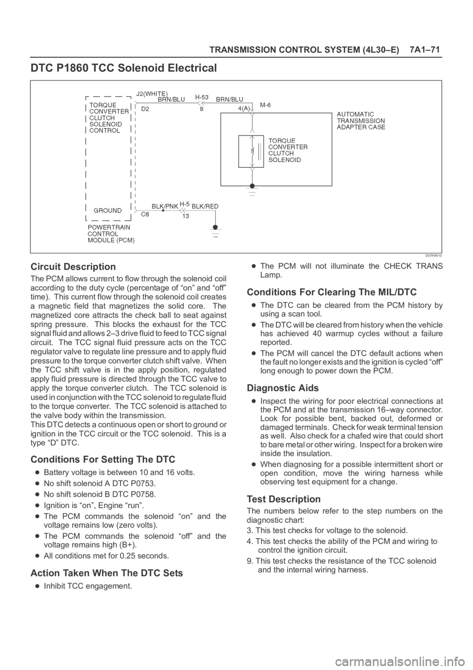
DTC P1860 TCC Solenoid Electrical
D07RW010
Circuit Description
The PCM allows current to flow through the solenoid coil
according to the duty cycle (percentage of “on” and “off”
time). This current flow through the solenoid coil creates
a magnetic field that magnetizes the solid core. The
magnetized core attracts the check ball to seat against
spring pressure. This blocks the exhaust for the TCC
signal fluid and allows 2–3 drive fluid to feed to TCC signal
circuit. The TCC signal fluid pressure acts on the TCC
regulator valve to regulate line pressure and to apply fluid
pressure to the torque converter clutch shift valve. When
the TCC shift valve is in the apply position, regulated
apply fluid pressure is directed through the TCC valve to
apply the torque converter clutch. The TCC solenoid is
used in conjunction with the TCC solenoid to regulate fluid
to the torque converter. The TCC solenoid is attached to
the valve body within the transmission.
This DTC detects a continuous open or short to ground or
ignition in the TCC circuit or the TCC solenoid. This is a
type “D” DTC.
Conditions For Setting The DTC
Battery voltage is between 10 and 16 volts.
No shift solenoid A DTC P0753.
No shift solenoid B DTC P0758.
Ignition is “on”, Engine “run”.
The PCM commands the solenoid “on” and the
voltage remains low (zero volts).
The PCM commands the solenoid “off” and the
voltage remains high (B+).
All conditions met for 0.25 seconds.
Action Taken When The DTC Sets
Inhibit TCC engagement.
The PCM will not illuminate the CHECK TRANS
Lamp.
Conditions For Clearing The MIL/DTC
The DTC can be cleared from the PCM history by
using a scan tool.
The DTC will be cleared from history when the vehicle
has achieved 40 warmup cycles without a failure
reported.
The PCM will cancel the DTC default actions when
the fault no longer exists and the ignition is cycled “off”
long enough to power down the PCM.
Diagnostic Aids
Inspect the wiring for poor electrical connections at
the PCM and at the transmission 16–way connector.
Look for possible bent, backed out, deformed or
damaged terminals. Check for weak terminal tension
as we ll. A lso ch eck fo r a ch af e d w ire th at cou l d s ho r t
to bare metal or other wiring. Inspect for a broken wire
inside the insulation.
When diagnosing for a possible intermittent short or
open condition, move the wiring harness while
observing test equipment for a change.
Test Description
The numbers below refer to the step numbers on the
diagnostic chart:
3. This test checks for voltage to the solenoid.
4. This test checks the ability of the PCM and wiring to
control the ignition circuit.
9. This test checks the resistance of the TCC solenoid
and the internal wiring harness.
Page 2540 of 6000
LIGHTING SYSTEM8A–1
BODY AND ACCESSORIES
CONTENTS
Lighting System 8A. . . . . . . . . . . . . . . . . . . . . . . . .
Wiper/Washer System 8B. . . . . . . . . . . . . . . . . . .
Entertainment 8C. . . . . . . . . . . . . . . . . . . . . . . . . . .
Wiring System 8D. . . . . . . . . . . . . . . . . . . . . . . . . .
Meter and Gauge 8E. . . . . . . . . . . . . . . . . . . . . . . Body Structure 8F. . . . . . . . . . . . . . . . . . . . . . . . . .
Seats 8G. . . . . . . . . . . . . . . . . . . . . . . . . . . . . . . . . .
Security and Locks 8H. . . . . . . . . . . . . . . . . . . . . .
Sun Roof/Convertible Top 8I. . . . . . . . . . . . . . . .
Exterior/Interior Trim 8J. . . . . . . . . . . . . . . . . . . . .
LIGHTING SYSTEM
CONTENTS
Service Precaution 8A–2. . . . . . . . . . . . . . . . . . . . . .
Headlight Bulb 8A–3. . . . . . . . . . . . . . . . . . . . . . . . . .
Removal 8A–3. . . . . . . . . . . . . . . . . . . . . . . . . . . . .
Installation 8A–3. . . . . . . . . . . . . . . . . . . . . . . . . . . .
Headlight 8A–4. . . . . . . . . . . . . . . . . . . . . . . . . . . . . . .
Headlight and Associated Parts 8A–4. . . . . . . . .
Removal 8A–4. . . . . . . . . . . . . . . . . . . . . . . . . . . . .
Installation 8A–4. . . . . . . . . . . . . . . . . . . . . . . . . . . .
Headlight Adjustment 8A–4. . . . . . . . . . . . . . . . . .
Fog Light Bulb 8A–5. . . . . . . . . . . . . . . . . . . . . . . . . .
Removal 8A–5. . . . . . . . . . . . . . . . . . . . . . . . . . . . .
Installation 8A–5. . . . . . . . . . . . . . . . . . . . . . . . . . . .
Fog Light Assembly 8A–6. . . . . . . . . . . . . . . . . . . . .
Removal 8A–6. . . . . . . . . . . . . . . . . . . . . . . . . . . . .
Installation 8A–6. . . . . . . . . . . . . . . . . . . . . . . . . . . .
Fog Light Adjustment 8A–6. . . . . . . . . . . . . . . . . .
Clarence Light Bulb 8A–6. . . . . . . . . . . . . . . . . . . . . .
Removal 8A–6. . . . . . . . . . . . . . . . . . . . . . . . . . . . .
Installation 8A–6. . . . . . . . . . . . . . . . . . . . . . . . . . . .
Rear Fog Light Bulb (RHD) 8A–7. . . . . . . . . . . . . . .
Removal 8A–7. . . . . . . . . . . . . . . . . . . . . . . . . . . . .
Installation 8A–7. . . . . . . . . . . . . . . . . . . . . . . . . . . .
Taillight Bulb (Body) 8A–7. . . . . . . . . . . . . . . . . . . . .
Removal 8A–7. . . . . . . . . . . . . . . . . . . . . . . . . . . . .
Installation 8A–7. . . . . . . . . . . . . . . . . . . . . . . . . . . .
Taillight Bulb (Bumper) 8A–8. . . . . . . . . . . . . . . . . . .
Removal 8A–8. . . . . . . . . . . . . . . . . . . . . . . . . . . . .
Installation 8A–8. . . . . . . . . . . . . . . . . . . . . . . . . . . .
License Plate Light Bulb (Body) 8A–8. . . . . . . . . . .
Removal 8A–8. . . . . . . . . . . . . . . . . . . . . . . . . . . . .
Installation 8A–8. . . . . . . . . . . . . . . . . . . . . . . . . . . .
License Plate Light Bulb (Bumper) 8A–9. . . . . . . . .
Removal 8A–9. . . . . . . . . . . . . . . . . . . . . . . . . . . . .
Installation 8A–9. . . . . . . . . . . . . . . . . . . . . . . . . . . .
Stoplight Bulb 8A–9. . . . . . . . . . . . . . . . . . . . . . . . . . .
Removal and Installation 8A–9. . . . . . . . . . . . . . . High Mount Stoplight 8A–10. . . . . . . . . . . . . . . . . . . .
Removal 8A–10. . . . . . . . . . . . . . . . . . . . . . . . . . . . .
Installation 8A–10. . . . . . . . . . . . . . . . . . . . . . . . . . . .
Front Turn Signal Light Bulb 8A–10. . . . . . . . . . . . . .
Removal 8A–10. . . . . . . . . . . . . . . . . . . . . . . . . . . . .
Installation 8A–10. . . . . . . . . . . . . . . . . . . . . . . . . . . .
Side Turn Signal Light Bulb 8A–11. . . . . . . . . . . . . . .
Removal 8A–11. . . . . . . . . . . . . . . . . . . . . . . . . . . . .
Installation 8A–11. . . . . . . . . . . . . . . . . . . . . . . . . . . .
Rear Turn Signal Light Bulb 8A–11. . . . . . . . . . . . . .
Removal 8A–11. . . . . . . . . . . . . . . . . . . . . . . . . . . . .
Installation 8A–11. . . . . . . . . . . . . . . . . . . . . . . . . . .
Backup Light Bulb 8A–12. . . . . . . . . . . . . . . . . . . . . . .
Removal 8A–12. . . . . . . . . . . . . . . . . . . . . . . . . . . . .
Installation 8A–12
. . . . . . . . . . . . . . . . . . . . . . . . . . .
Dome Light Bulb 8A–12. . . . . . . . . . . . . . . . . . . . . . . .
Removal 8A–12. . . . . . . . . . . . . . . . . . . . . . . . . . . . .
Installation 8A–12. . . . . . . . . . . . . . . . . . . . . . . . . . . .
Luggage Room Light Bulb 8A–13. . . . . . . . . . . . . . . .
Removal 8A–13. . . . . . . . . . . . . . . . . . . . . . . . . . . . .
Installation 8A–13. . . . . . . . . . . . . . . . . . . . . . . . . . . .
Courtesy Light Bulb 8A–13. . . . . . . . . . . . . . . . . . . . . .
Removal 8A–13. . . . . . . . . . . . . . . . . . . . . . . . . . . . .
Installation 8A–13. . . . . . . . . . . . . . . . . . . . . . . . . . . .
Map Light Switch/Bulb 8A–14. . . . . . . . . . . . . . . . . . .
Removal 8A–14. . . . . . . . . . . . . . . . . . . . . . . . . . . . .
Installation 8A–14. . . . . . . . . . . . . . . . . . . . . . . . . . . .
Cigarette Lighter Illumination Bulb 8A–14. . . . . . . . .
Removal 8A–14. . . . . . . . . . . . . . . . . . . . . . . . . . . . .
Installation 8A–14. . . . . . . . . . . . . . . . . . . . . . . . . . .
Ashtray Illumination Bulb 8A–15. . . . . . . . . . . . . . . . .
Removal 8A–15. . . . . . . . . . . . . . . . . . . . . . . . . . . . .
Installation 8A–15. . . . . . . . . . . . . . . . . . . . . . . . . . . .
Glove Box Illumination Bulb 8A–15. . . . . . . . . . . . . . .
Removal 8A–15. . . . . . . . . . . . . . . . . . . . . . . . . . . . .
Installation 8A–15. . . . . . . . . . . . . . . . . . . . . . . . . . . .
Page 2541 of 6000
8A–2LIGHTING SYSTEM
Vanity Mirror Illumination Bulb 8A–16. . . . . . . . . . . . .
Removal 8A–16. . . . . . . . . . . . . . . . . . . . . . . . . . . . .
Installation 8A–16. . . . . . . . . . . . . . . . . . . . . . . . . . .
Starter Switch 8A–17. . . . . . . . . . . . . . . . . . . . . . . . . . .
Removal 8A–17. . . . . . . . . . . . . . . . . . . . . . . . . . . . .
Installation 8A–17. . . . . . . . . . . . . . . . . . . . . . . . . . . .
Lighting Switch (Combination Switch) 8A–18. . . . . .
Removal 8A–18. . . . . . . . . . . . . . . . . . . . . . . . . . . . .
Installation 8A–18. . . . . . . . . . . . . . . . . . . . . . . . . . . .
Fog Light Switch 8A–19. . . . . . . . . . . . . . . . . . . . . . . .
Removal 8A–19. . . . . . . . . . . . . . . . . . . . . . . . . . . . .
Installation 8A–19. . . . . . . . . . . . . . . . . . . . . . . . . . . .
Stoplight Switch (W/O Cruise Control) 8A–20. . . . . .
Removal 8A–20. . . . . . . . . . . . . . . . . . . . . . . . . . . . .
Installation 8A–20. . . . . . . . . . . . . . . . . . . . . . . . . . . .
Brake Switch (W/Cruise Control) 8A–21. . . . . . . . . .
Removal 8A–21. . . . . . . . . . . . . . . . . . . . . . . . . . . . .
Installation 8A–21. . . . . . . . . . . . . . . . . . . . . . . . . . . .
Turn Signal Switch (Combination Switch) 8A–21. . .
Removal and Installation 8A–21. . . . . . . . . . . . . . .
Hazard Warning Switch 8A–22. . . . . . . . . . . . . . . . . .
Removal 8A–22. . . . . . . . . . . . . . . . . . . . . . . . . . . . . Installation 8A–22. . . . . . . . . . . . . . . . . . . . . . . . . . . .
Tailgate Switch 8A–23. . . . . . . . . . . . . . . . . . . . . . . . . .
Removal 8A–23. . . . . . . . . . . . . . . . . . . . . . . . . . . . .
Installation 8A–23. . . . . . . . . . . . . . . . . . . . . . . . . . . .
Door Switch 8A–23. . . . . . . . . . . . . . . . . . . . . . . . . . . .
Removal 8A–23. . . . . . . . . . . . . . . . . . . . . . . . . . . . .
Installation 8A–23. . . . . . . . . . . . . . . . . . . . . . . . . . . .
Rear Defogger Switch 8A–24. . . . . . . . . . . . . . . . . . .
Removal 8A–24. . . . . . . . . . . . . . . . . . . . . . . . . . . . .
Installation 8A–24. . . . . . . . . . . . . . . . . . . . . . . . . . .
Seat Heater Switch 8A–25. . . . . . . . . . . . . . . . . . . . . .
Removal 8A–25. . . . . . . . . . . . . . . . . . . . . . . . . . . . .
Installation 8A–25. . . . . . . . . . . . . . . . . . . . . . . . . . . .
Key Remind Switch (Starter Switch) 8A–25. . . . . . .
Removal and Installation 8A–25. . . . . . . . . . . . . . .
Illumination Controller 8A–26. . . . . . . . . . . . . . . . . . . .
Removal 8A–26. . . . . . . . . . . . . . . . . . . . . . . . . . . . .
Installation 8A–26. . . . . . . . . . . . . . . . . . . . . . . . . . .
Power/Winter Switch 8A–27. . . . . . . . . . . . . . . . . . . . .
Removal 8A–27. . . . . . . . . . . . . . . . . . . . . . . . . . . . .
Installation 8A–27. . . . . . . . . . . . . . . . . . . . . . . . . . .
Main Data and Specifications 8A–28. . . . . . . . . . . . .
Service Precaution
WARNING: IF SO EQUIPPED WITH A
SUPPLEMENTAL RESTRAINT SYSTEM (SRS),
REFER TO THE SRS COMPONENT AND WIRING
LOCATION VIEW IN ORDER TO DETERMINE
WHETHER YOU ARE PERFORMING SERVICE ON OR
NEAR THE SRS COMPONENTS OR THE SRS
WIRING. WHEN YOU ARE PERFORMING SERVICE
ON OR NEAR THE SRS COMPONENTS OR THE SRS
WIRING, REFER TO THE SRS SERVICE
INFORMATION. FAILURE TO FOLLOW WARNINGS
COULD RESULT IN POSSIBLE AIR BAG
DEPLOYMENT, PERSONAL INJURY, OR
OTHERWISE UNNEEDED SRS SYSTEM REPAIRS.
CAUTION: Always use the correct fastener in the
proper location. When you replace a fastener, use
ONLY the exact part number for that application.
ISUZU will call out those fasteners that require a
replacement after removal. ISUZU will also call out
the fasteners that require thread lockers or thread
sealant. UNLESS OTHERWISE SPECIFIED, do not
use supplemental coatings (Paints, greases, or other
corrosion inhibitors) on threaded fasteners or
fastener joint interfaces. Generally, such coatings
adversely affect the fastener torque and the joint
clamping force, and may damage the fastener. When
you install fasteners, use the correct tightening
sequence and specifications. Following these
instructions can help you avoid damage to parts and
systems.
Page 2564 of 6000

LIGHTING SYSTEM8A–25
Seat Heater Switch
Removal
1. Disconnect the battery ground cable.
2. Remove four fixing screws and disconnect the switch
connectors to remove the front console assembly(4).
3. Push the lock from the back side of the front console
assembly to remove the seat heater switch(5).
825RW025
Installation
To install, follow the removal steps in the reverse order,
noting the following point.
1. Push the switch with your fingers until it locks
securely.
Key Remind Switch (Starter Switch)
Removal and Installation
Refer to the removal and installation on steps of the
Starter Switch in this section.
Page 2568 of 6000
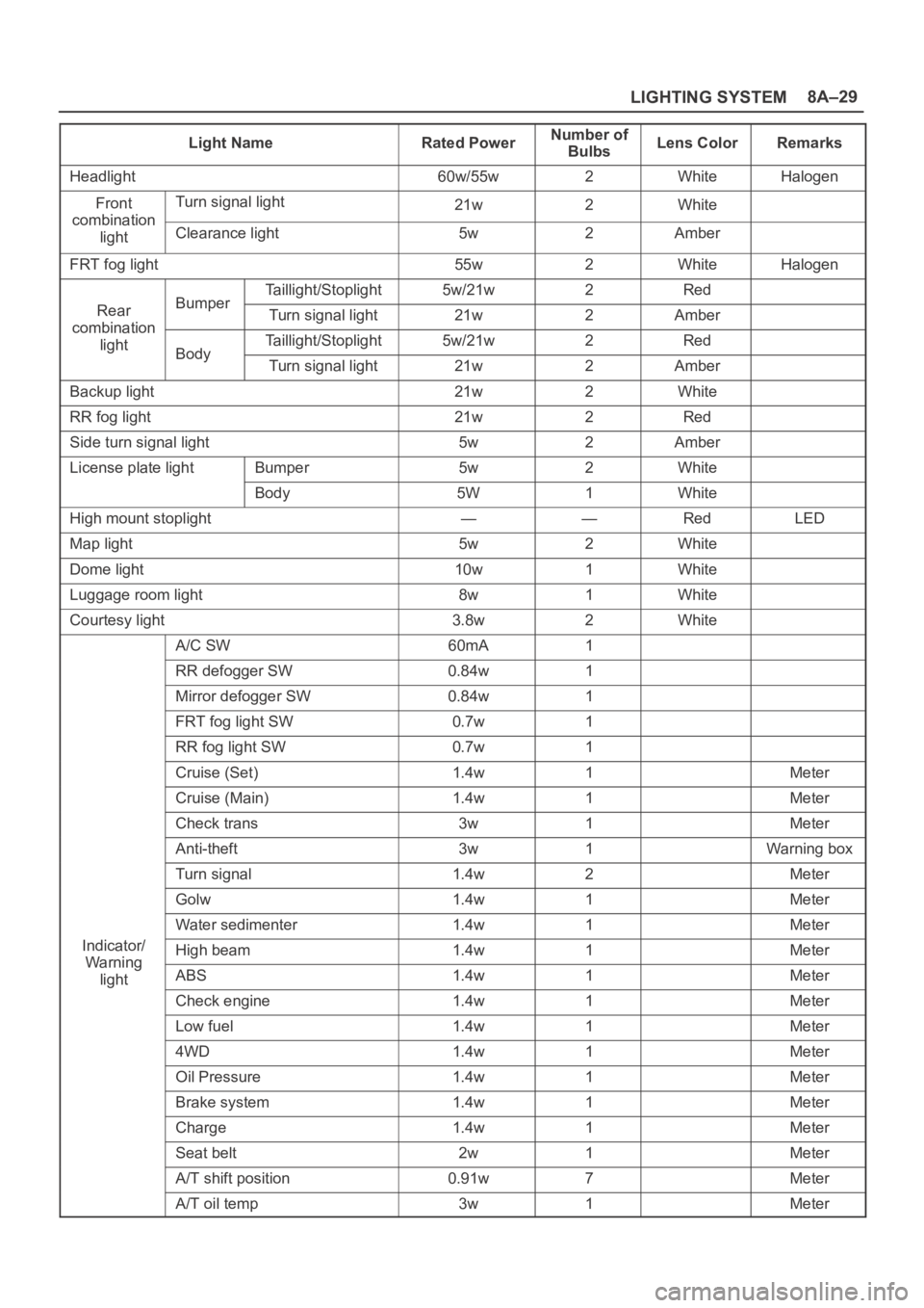
LIGHTING SYSTEM8A–29
Light NameRated PowerNumber of
BulbsLens ColorRemarks
Headlight60w/55w2WhiteHalogen
FrontTurn signal light21w2Whitecombination
lightClearance light5w2Amber
FRT fog light55w2WhiteHalogen
Taillight/Stoplight5w/21w2Red
RearBumperTurn signal light21w2Ambercombination
lightTaillight/Stoplight5w/21w2RedBodyTurn signal light21w2Amber
Backup light21w2White
RR fog light21w2Red
Side turn signal light5w2Amber
License plate lightBumper5w2White
Body5W1White
High mount stoplight——RedLED
Map light5w2White
Dome light10w1White
Luggage room light8w1White
Courtesy light3.8w2White
A/C SW60mA1
RR defogger SW0.84w1
Mirror defogger SW0.84w1
FRT fog light SW0.7w1
RR fog light SW0.7w1
Cruise (Set)1.4w1Meter
Cruise (Main)1.4w1Meter
Check trans3w1Meter
Anti-theft3w1Warning box
Turn signal1.4w2Meter
Golw1.4w1Meter
Water sedimenter1.4w1Meter
Indicator/High beam1.4w1MeterWa rnin g
lightABS1.4w1Meter
Check engine1.4w1Meter
Low fuel1.4w1Meter
4WD1.4w1Meter
Oil Pressure1.4w1Meter
Brake system1.4w1Meter
Charge1.4w1Meter
Seat belt2w1Meter
A/T shift position0.91w7Meter
A/T oil temp3w1Meter
Page 2650 of 6000
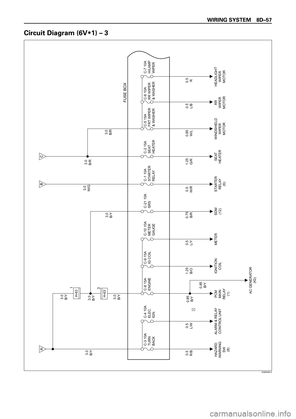
3.0
B/Y3.0
B/Y
3.0
B/Y3.0
B/Y3.0
W/G3.0
B/R
3.0
B/R 3.0
B/Y
0.5
R/B
HAZARD
WARNING
SW
(8)PCM
MAIN
RELAY
(1)IGNITION
COILMETER STARTER
RELAY
(6)SEAT
HEATERWINDSHIELD
WIPER
MOTORRR
WIPER
MOTORHEADLIGHT
WIPER
MOTOR
AC GENERATOR
(IG) ALARM & RELAY
CONTROL UNIT C-3 10A
TURN
BACK
0.5
L/WC-4 10A
ELEC.
IGN.
0.5
L/YC-10 10A
METER
GAUGE
0.5
W/RC-1 10A
STARTER
RELAY
0.85
W/LC-5 15A
FRT WIPER
& WASHERC-6 10A
RR WIPER
& WASHERC-7 10A
H/LAMP
WIPER
FUSE BOX
1.25
B/OC-9 15A
IG COIL C-8 15A
ENGINE
0.5
L/B
0.85
B/Y
0.85
B/Y
0.5
R
0.75
B/R
SDM
(12)C-21 10A
SRS
1.25
G/RC-2 15A
SEAT
HEATER
H-631
3
H-63
��
D08RWB15
Page 2658 of 6000

3.0
B/Y3.0
B/Y
3.0
B/Y3.0
B/Y3.0
W/G3.0
B/R
3.0
B/R 3.0
B/Y
0.5
R/B
HAZARD
WARNING
SW
(8)C-3 10A
TURN
BACK
0.5
L/WC-4 10A
ELEC.
IGN.
0.5
L/Y
METER ECM
(J2-9) ALARM & RELAY��
C O NTR O L UNITC-10 10A
METER
GAUGE
0.5
W/R
STARTER
RELAY
(6)C-1 10A
STARTER
RELAY
0.85
W/L
WINDSHIELD
WIPER
MOTORC-5 15A
FRT WIPER
& WASHERC-6 10A
RR WIPER
& WASHERC-7 10A
H/LAMP
WIPER
FUSE BOX
C-8 15A
ENGINE
0.5
L/B
RR
WIPER
MOTORHEADLIGHT
WIPER
MOTOR
0.85
B/Y
0.5
R
0.75
B/R
SDM
(12)C-21 10A
SRS
1.25
G/R
SEAT
HEATERC-2 15A
SEAT
HEATER
H-631
3
H-63
��
D08RWB20