check engine OPEL FRONTERA 1998 Workshop Manual
[x] Cancel search | Manufacturer: OPEL, Model Year: 1998, Model line: FRONTERA, Model: OPEL FRONTERA 1998Pages: 6000, PDF Size: 97 MB
Page 2093 of 6000

6E–200
4JX1–TC ENGINE DRIVEABILITY AND EMISSIONS
SymptomsInitial DiagnosisDefault Section(s)
Hesitation, Sag, Stumble1. OBD system check.
2. AP.
3. MAP output check.
4. Fuel system diagnosis.
5. Injector system.Generator Output Voltage (refer
to
Chassis Electrical),
Calibration ID/Service Bulletins,
Ignition System Check
Rough, Unstable, or Incorrect Idle,
Stalling1. OBD system check.
2. Fuel injector test.MAP Output Check, Throttle
Linkage, A/C Clutch Control
Circuit Diagnosis, Calibration
ID/Service Bulletins, Generator
Output Voltage (refer to
Chassis
Electrical
), Exhaust Diagnosis
Poor Fuel Economy1. OBD system check.
2. Careful visual/physical inspection.
3. Injector system.
4. Cooling system.TCC Operation, Exhaust
System (refer to
Engine
Exhaust
)
Engine Cranks But Will Not Run1. OBD system check.Fuel System Electrical
Diagnosis, Fuel System
Diagnosis, Fuel Injector Test.
Excessive Exhaust Emissions or
Odors1. OBD system check.
2. Emission test.
3. Cooling system.
4. Fuel system diagnosis.
5. Fuel injector test.
6. Injector system.
7. MAP output check.Exhaust Diagnosis, Calibration
ID/Service Bulletins
Dieseling, Run-On1. OBD system check.
2. Careful visual/physical inspection.
3. Fuel system diagnosis.—
Page 2100 of 6000

6E–207 4JX1–TC ENGINE DRIVEABILITY AND EMISSIONS
damage, therefore, it is important to use care when
handling and testing electronic components.
NOTE: To prevent possible Electrostatic Discharge
damage, follow these guidelines:
Do not touch the control module connector pins or
soldered components on the control module circuit
board.
Do not open the replacement part package until the
part is ready to be installed.
Before removing the part from the package, ground
the package to a known good ground on the vehicle.
If the part has been handled while sliding across the
seat, or while sitting down from a standing position, or
while walking a distance, touch a known good ground
before installing the part.
NOTE: To prevent internal ECM damage, the ignition
must be in the “OFF” position in order to disconnect or
reconnect power to the ECM (for example: battery cable,
ECM pigtail, ECM fuse, jumper cables, etc.).
IMPORTANT:When replacing the production ECM
with a service ECM, it is important to transfer the
broadcast code and production ECM number to the
service ECM label. This will allow positive identification of
ECM parts throughout the service life of the vehicle. Do
not record this information on the metal ECM cover.
IMPORTANT:The ignition should always be in the
“OFF” position in order to install or remove the ECM
connectors.
Service of the ECM should normally consist of either re-
placement of the ECM. If the diagnostic procedures call
for the ECM to be replaced, the ECM should be checked
first to ensure it is the correct part. If it is, remove the
faulty ECM and install the new service ECM.
DTC P0601 indicates the check sum error.
Removal Procedure
1. Disconnect the negative battery cable.
2. Disconnect the ECM connector.
035RW093
3. Remove the bolts ECM bracket and battery bracket.
035RW094
4. Remove the ECM.
035RW092
Page 2101 of 6000

6E–208
4JX1–TC ENGINE DRIVEABILITY AND EMISSIONS
Installation Procedure
1. Install the ECM.
035RW092
2. Install the bolts, ECM bracket and battery bracket.
035RW094
3. Connect the ECM connector.
035RW093
4. Connect the negative battery cable.
If the ECM is replaced, the new ECM will need to be
programmed.
EEPROM
General Description
The Electronically Erasable Programmable Read Only
Memory (EEPROM) is a permanent memory that is
physically soldered within the ECM. The EEPROM
contains program and calibration information that the
ECM needs to control powertrain operation.
Functional Check
1. Perform the On-Board Diagnostic System Check.
2. Start the engine and run for one minute.
3. Scan for DTCs using the Tech 2.
Intake Throttle Position (ITP)
Sensor
Removal Procedure
1. Disconnect the negative battery cable.
Page 2102 of 6000

6E–209 4JX1–TC ENGINE DRIVEABILITY AND EMISSIONS
2. Remove the cover of the intercooler.
035RW051
3. Remove the bolts and the left side bracket to the
intercooler.
4 . R e m o v e t h e a i r d u c t w i t h b r a c k e t f r o m t h e i n t e r c o o l e r.
5. Remove the throttle body from the intake manifold.
6. Disconnect the ITP sensor electrical connector and
throttle motor control connector.
7. Remove the bolts and the ITP sensor from the throttle
body.
035RW086
NOTE: Do not clean the ITP sensor by soaking it in
solvent. The sensor will be damaged as a result.
Function Check
Use a Tech 2 to check the ITP sensor output voltage at
closed throttle.
The voltage should be under 0.85 volt.
If the reading is greater than 0.85 volt, check the
throttle shaft to see if it is binding.
If the throttle shaft is not binding and the throttle cable
is properly adjusted, install a new ITP sensor.
Installation Procedure
1. Install the ITP sensor on the throttle body with the
bolts.
035RW051
2. Install the throttle body to the intake manifold and the
air duct with bracket between throttle body and
intercooler.
Torque: 20 Nꞏm (14 Ib ft)
035RW086
3. Connect the ITP sensor electrical connector and
throttle motor control connector.
4. Install the bracket to the intercooler.
5. Install the cover of intercooler.
6. Install the negative battery cable.
Page 2103 of 6000

6E–210
4JX1–TC ENGINE DRIVEABILITY AND EMISSIONS
Vehicle Speed Sensor (VSS)
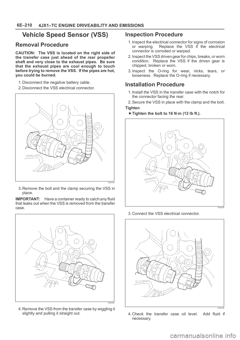
Removal Procedure
CAUTION: The VSS is located on the right side of
the transfer case just ahead of the rear propeller
shaft and very close to the exhaust pipes. Be sure
that the exhaust pipes are cool enough to touch
before trying to remove the VSS. If the pipes are hot,
you could be burned.
1. Disconnect the negative battery cable.
2. Disconnect the VSS electrical connector.
TS23748
3. Remove the bolt and the clamp securing the VSS in
place.
IMPORTANT:H a v e a c o n t a i n e r r e a d y t o c a t c h a n y f l u i d
that leaks out when the VSS is removed from the transfer
case.
TS23780
4. Remove the VSS from the transfer case by wiggling it
slightly and pulling it straight out.
Inspection Procedure
1. Inspect the electrical connector for signs of corrosion
or warping. Replace the VSS if the electrical
connector is corroded or warped.
2. Inspect the VSS driven gear for chips, breaks, or worn
condition. Replace the VSS if the driven gear is
chipped, broken or worn.
3. Inspect the O-ring for wear, nicks, tears, or
looseness. Replace the O-ring if necessary.
Installation Procedure
1. Install the VSS in the transfer case with the notch for
the connector facing the rear.
2. Secure the VSS in place with the clamp and the bolt.
Tighten
Tighten the bolt to 16 Nꞏm (12 lb ft.).
TS23780
3. Connect the VSS electrical connector.
TS23748
4. Check the transfer case oil level. Add fluid if
necessary.
Page 2106 of 6000

6E–213 4JX1–TC ENGINE DRIVEABILITY AND EMISSIONS
3. Connect the electrical connector to the AP sensor.
035RW060
4. Connect the negative battery cable.
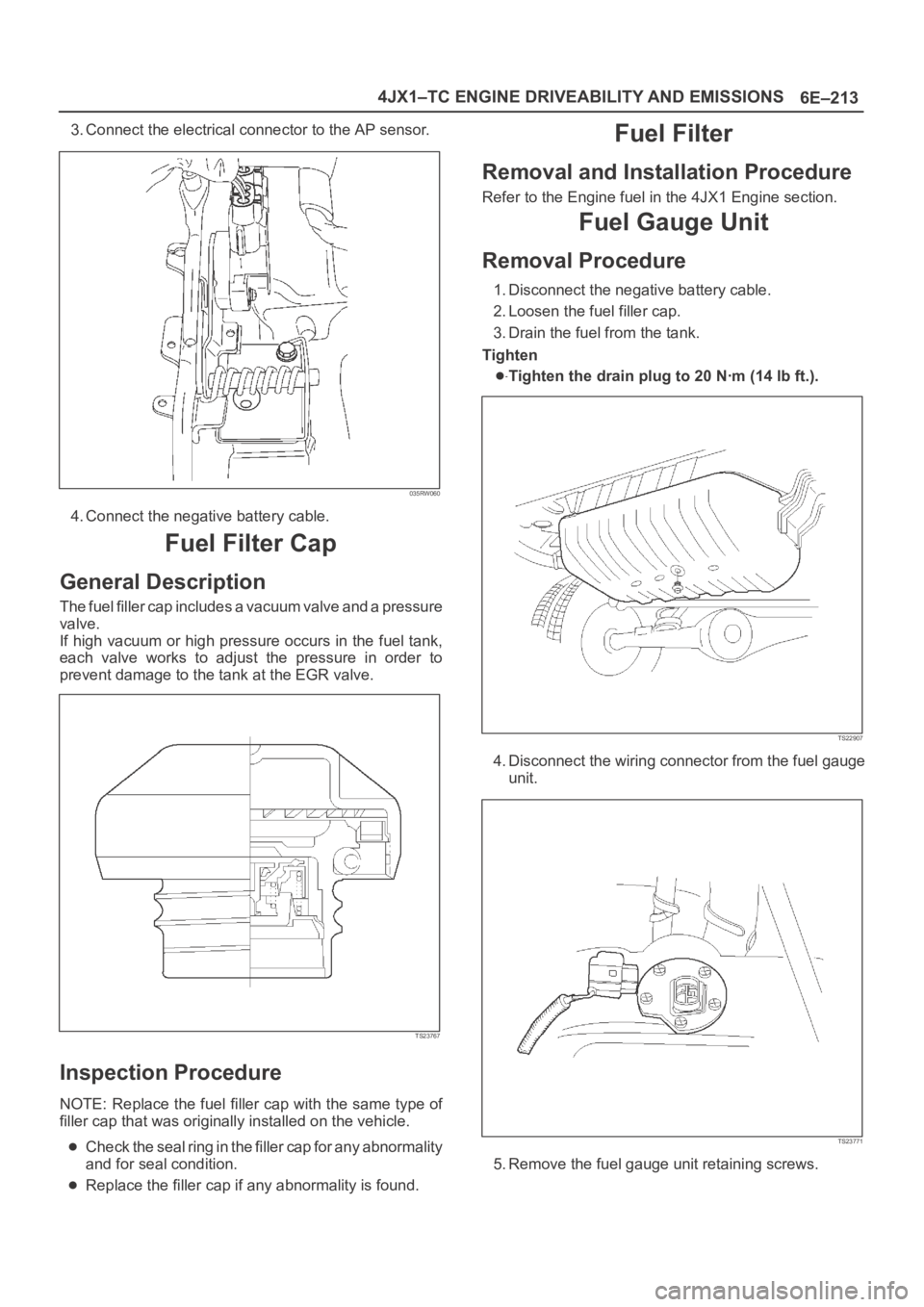
Fuel Filter Cap
General Description
The fuel filler cap includes a vacuum valve and a pressure
valve.
If high vacuum or high pressure occurs in the fuel tank,
each valve works to adjust the pressure in order to
prevent damage to the tank at the EGR valve.
TS23767
Inspection Procedure
NOTE: Replace the fuel filler cap with the same type of
filler cap that was originally installed on the vehicle.
Check the seal ring in the filler cap for any abnormality
and for seal condition.
Replace the filler cap if any abnormality is found.
Fuel Filter
Removal and Installation Procedure
Refer to the Engine fuel in the 4JX1 Engine section.
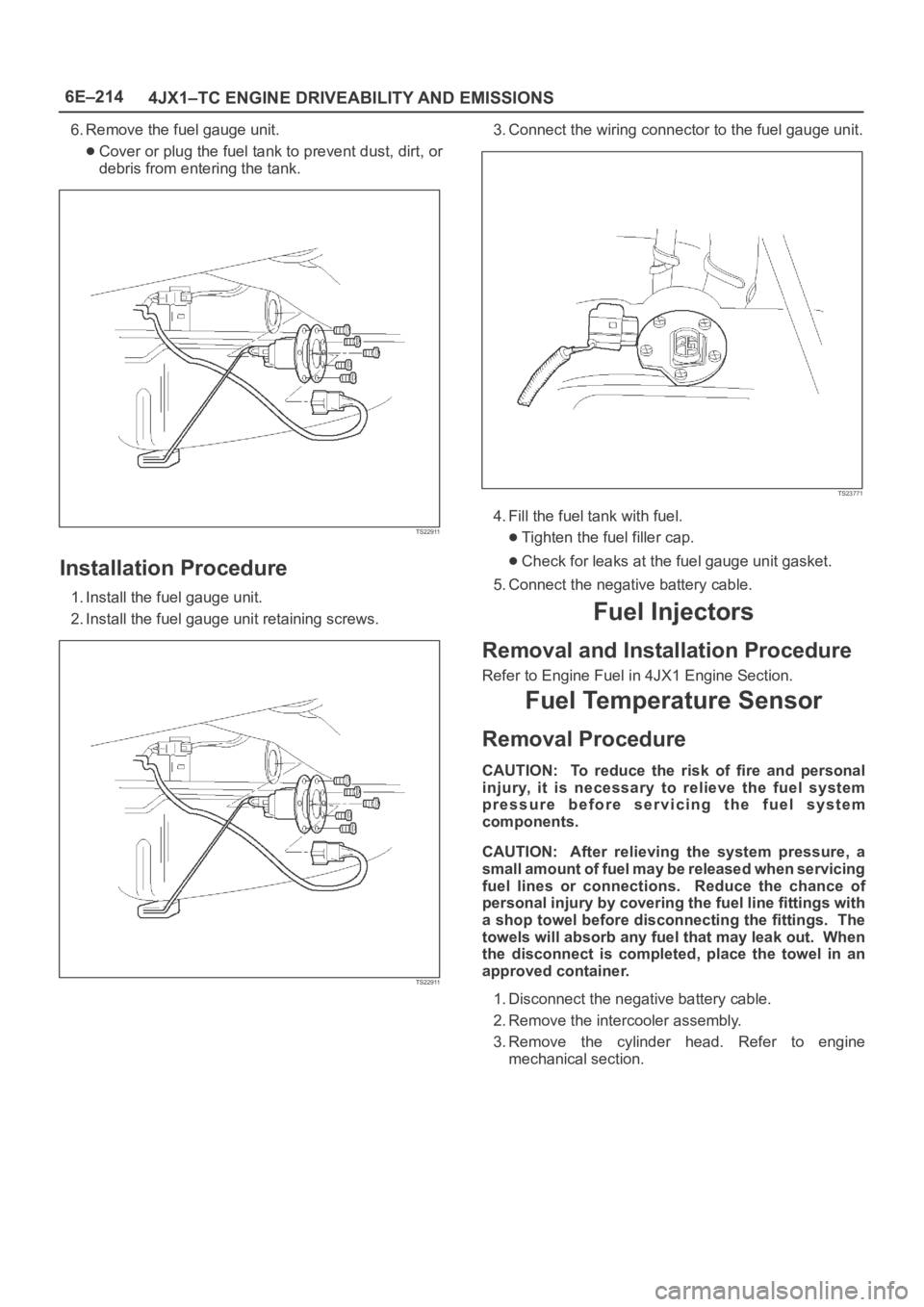
Fuel Gauge Unit
Removal Procedure
1. Disconnect the negative battery cable.
2. Loosen the fuel filler cap.
3. Drain the fuel from the tank.
Tighten
Tighten the drain plug to 20 Nꞏm (14 lb ft.).
TS22907
4. Disconnect the wiring connector from the fuel gauge
unit.
TS23771
5. Remove the fuel gauge unit retaining screws.
Page 2107 of 6000

6E–214
4JX1–TC ENGINE DRIVEABILITY AND EMISSIONS
6. Remove the fuel gauge unit.
Cover or plug the fuel tank to prevent dust, dirt, or
debris from entering the tank.
TS22911
Installation Procedure
1. Install the fuel gauge unit.
2. Install the fuel gauge unit retaining screws.
TS22911
3. Connect the wiring connector to the fuel gauge unit.
TS23771
4. Fill the fuel tank with fuel.
Tighten the fuel filler cap.
Check for leaks at the fuel gauge unit gasket.
5. Connect the negative battery cable.
Fuel Injectors
Removal and Installation Procedure
Refer to Engine Fuel in 4JX1 Engine Section.
Fuel Temperature Sensor
Removal Procedure
CAUTION: To reduce the risk of fire and personal
injury, it is necessary to relieve the fuel system
pressure before servicing the fuel system
components.
CAUTION: After relieving the system pressure, a
small amount of fuel may be released when servicing
fuel lines or connections. Reduce the chance of
personal injury by covering the fuel line fittings with
a shop towel before disconnecting the fittings. The
towels will absorb any fuel that may leak out. When
the disconnect is completed, place the towel in an
approved container.
1. Disconnect the negative battery cable.
2. Remove the intercooler assembly.
3. Remove the cylinder head. Refer to engine
mechanical section.
Page 2113 of 6000

6E–220
4JX1–TC ENGINE DRIVEABILITY AND EMISSIONS
Installation Procedure
1. Install the EVRV.
035RW064
2. Connect the EVRV hose and the EVRV connector.
035RW065
3. Connect the negative battery cable.
Wiring and Connectors
Wiring Harness Service
The ECM harness electrically connects the ECM to the
various solenoids, switches and sensors in the vehicle
engine compartment and passenger compartment.
Replace wire harnesses with the proper part number
replacement.
Because of the low amperage and voltage levels utilized
in powertrain control systems, it is essential that all wiring
in environmentally exposed areas be repaired with crimp
and seal splice sleeves.The following wire harness repair information is intended
as a general guideline only. Refer to
Chassis Electrical f o r
all wire harness repair procedures.
Connectors and Terminals
Use care when probing a connector and when replacing
terminals. It is possible to short between opposite
terminals. Damage to components could result. Always
use jumper wires between connectors for circuit
checking. NEVER probe through Weather-Pack seals.
Use an appropriate connector test adapter kit which
contains an assortment of flexible connectors used to
probe terminals during diagnosis. Use an appropriate
fuse remover and test tool for removing a fuse and to
adapt the fuse holder to a meter for diagnosis.
Open circuits are often difficult to locate by sight because
oxidation or terminal misalignment are hidden by the
connectors. Merely wiggling a connector on a sensor, or
in the wiring harness, may temporarily correct the open
circuit. Intermittent problems may also be caused by
oxidized or loose connections.
Be certain of the type of connector/terminal before
making any connector or terminal repair. Weather-Pack
and Com-Pack III terminals look similar, but are serviced
differently.
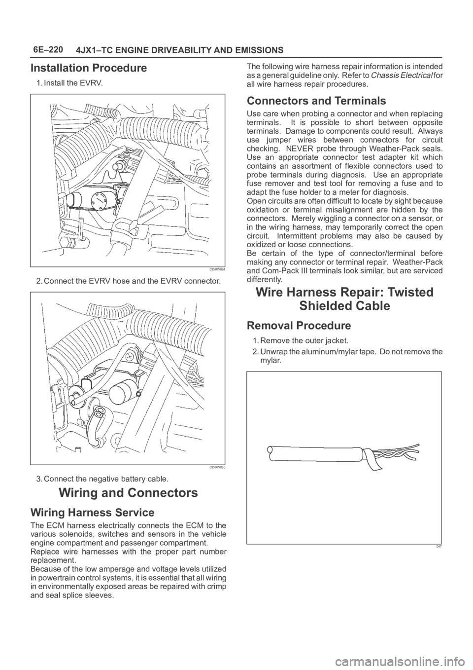
Wire Harness Repair: Twisted
Shielded Cable
Removal Procedure
1. Remove the outer jacket.
2. Unwrap the aluminum/mylar tape. Do not remove the
mylar.
047
Page 2125 of 6000

6F – 2 ENGINE EXHAUST
GENERAL DESCRIPTION
150RW070
When inspecting or replacing exhaust system
components, make sure there is adequate clearance
from all points on the underbody to prevent overheating
of the floor pan and possible damage to the passenger
compartment insulation and trim materials.
Check complete exhaust system and nearby body
areas and rear compartment lid for broken, damaged,
missing or mispositioned parts, open seams, holes
loose connections or other deterioration which could
permit exhaust fumes to seep into the rear
compartment or passenger compartment. Dust or water
in the rear compartment may be an indication of a
problem in one of these areas. Any faulty areas should
be corrected immediately.HANGERS
Various types of hangers are used to support exhaust
system(s). These include conventional rubber straps,
rubber rings, and rubber blocks.
The installation of exhaust system supports is very
important, as improperly installed supports can cause
annoying vibrations which can be difficult to diagnose.
GASKET
The gasket must be replaced whenever a new exhaust
pipe, muffler or exhaust throttle is installed.
Page 2126 of 6000

ENGINE EXHAUST 6F – 3
ON-VEHICLE SERVICE
FRONT EXHAUST PIPE
Rattles and noise vibrations in the exhaust system are
usually caused by misalignment of parts. When aligning
the system, leave all bolts or nuts loose until all parts
are properly aligned; then tighten, working from front to
rear.
1. Check connections for looseness or damage,
especially for exhaust gas leakage.
2. Check clamps and rubbers for weakness, cracks or
damage.3. If any part of the converter heat shield is damaged
or dented to the extent that it contacts the catalyst,
repair or replace.
4. Check for dents or damage and for any holes or
cracks caused by corrosion.
3
2 1
Legend
(1) Front exhaust pipe
(2) Center exhaust pipe
(3) Mounting rubber
150RW071