4WD OPEL FRONTERA 1998 Repair Manual
[x] Cancel search | Manufacturer: OPEL, Model Year: 1998, Model line: FRONTERA, Model: OPEL FRONTERA 1998Pages: 6000, PDF Size: 97 MB
Page 764 of 6000
TRANSFER CASE (STANDARD TYPE)
4D1–43
Main Data and Specifications
General Specifications
Ty p eW/Shift On The Fly System model
Synchronized type gears shifting between the 2 and 4 wheel drive mode.
Constant mesh type gears shifting between “low” and “high”.
WO/Shift On The Fly System model
Constant mesh type gears shifting between the 2 and 4 wheel drive mode,
and between “low” and “high”.
Control methodW/4WD Switch model
Electric control with the button switch on the instrument panel for gear
shifting between the 2 and 4 wheel drive mode.
Remote control with the gear shift lever on the floor for gear shifting
between “low and high” .
WO/4WD Switch model
Remote control with the gear shift lever on the floor for gear shifting.
Gear ratioHigh; 1.000
Low; 2.050
Oil capacity1.45 lit. (1.53 U.S. quart)
Type of lubricantEngine oil
Refer to chart in Section 0
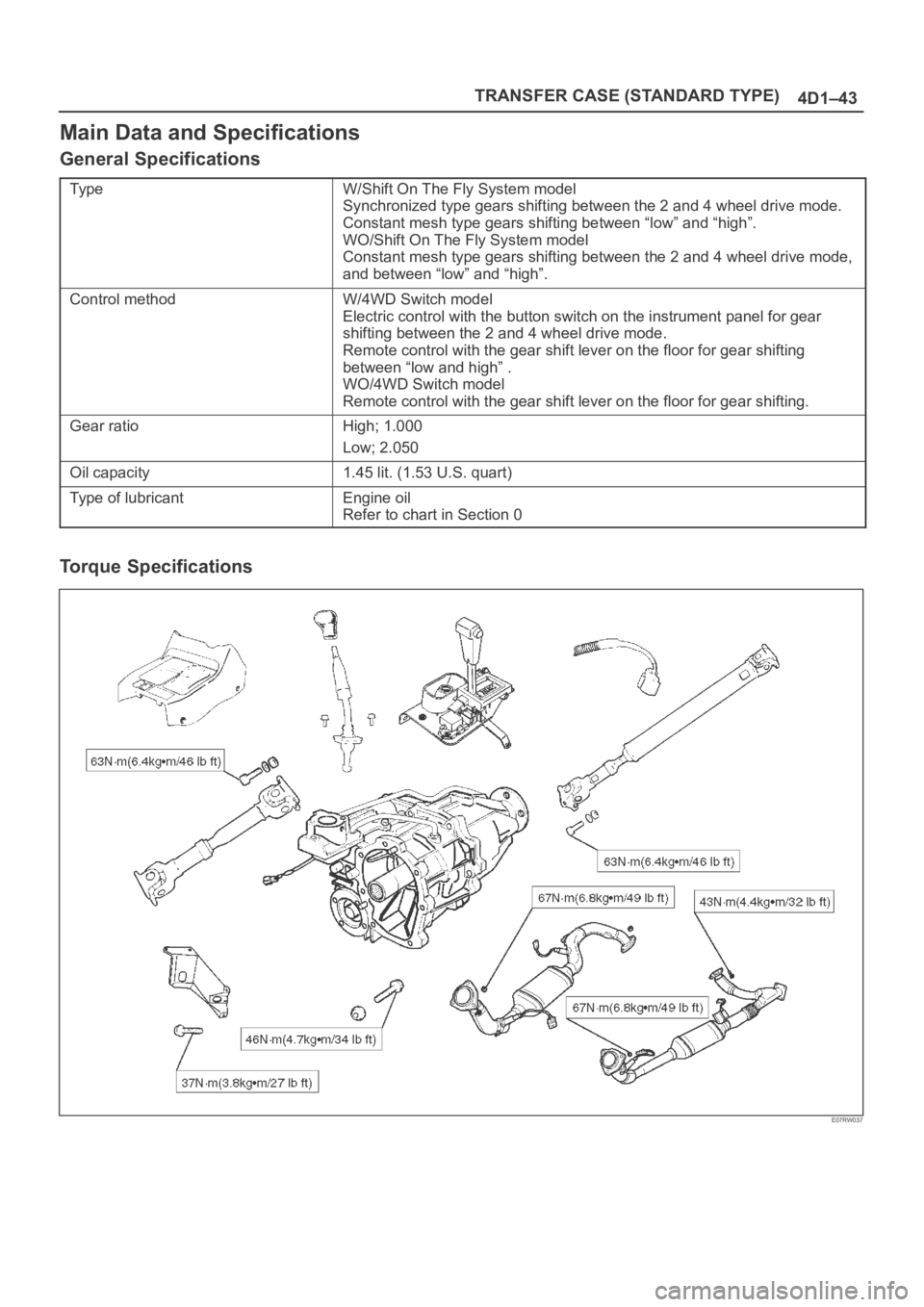
Torque Specifications
E07RW037
Page 814 of 6000
5A–4
BRAKE CONTROL SYSTEM
normal braking when a malfunction has occurred in the
ABS.
The EHCU has a self-diagnosing function which can
indicate faulty circuits during diagnosis.
The EHCU is mounted on the engine compartment front
right side. It consists of a Motor, Plunger Pump, Solenoid
Valves and Check Valve.
On the outside, the relay box containing a motor relay and
a valve relay is installed.
Solenoid Valves: Reduces or holds the caliper fluid
pressure for each front disc brake or both rear disc brakes
according to the signal sent from the EHCU.
Reservoir: Temporarily holds the brake fluid that returns
from the front and rear disc brake caliper so that pressure
of front disc brake caliper can be reduced smoothly.
Plunger Pump: Feeds the brake fluid held in the reservoir
to the master cylinder.
Motor: Drives the pump according to the signal from
EHCU.
Check Valve: Controls the brake fluid flow.
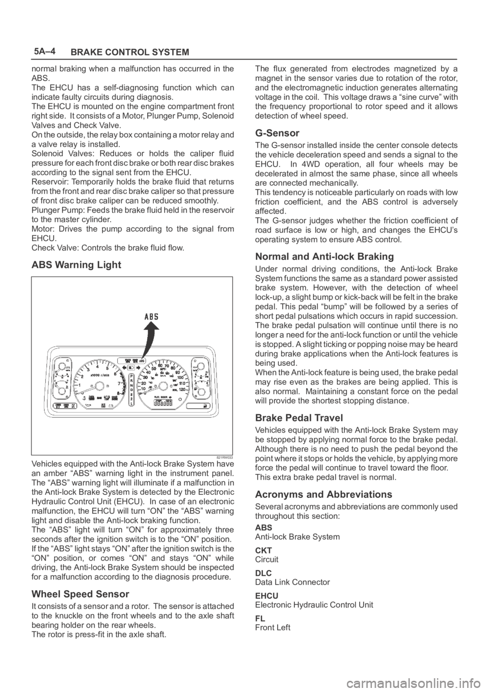
ABS Warning Light
821RW033Vehicles equipped with the Anti-lock Brake System have
an amber “ABS” warning light in the instrument panel.
The “ABS” warning light will illuminate if a malfunction in
the Anti-lock Brake System is detected by the Electronic
Hydraulic Control Unit (EHCU). In case of an electronic
malfunction, the EHCU will turn “ON” the “ABS” warning
light and disable the Anti-lock braking function.
The “ABS” light will turn “ON” for approximately three
seconds after the ignition switch is to the “ON” position.
If the “ABS” light stays “ON” after the ignition switch is the
“ON” position, or comes “ON” and stays “ON” while
driving, the Anti-lock Brake System should be inspected
for a malfunction according to the diagnosis procedure.
Wheel Speed Sensor
It consists of a sensor and a rotor. The sensor is attached
to the knuckle on the front wheels and to the axle shaft
bearing holder on the rear wheels.
The rotor is press-fit in the axle shaft.The flux generated from electrodes magnetized by a
magnet in the sensor varies due to rotation of the rotor,
and the electromagnetic induction generates alternating
voltage in the coil. This voltage draws a “sine curve” with
the frequency proportional to rotor speed and it allows
detection of wheel speed.
G-Sensor
The G-sensor installed inside the center console detects
the vehicle deceleration speed and sends a signal to the
EHCU. In 4WD operation, all four wheels may be
decelerated in almost the same phase, since all wheels
are connected mechanically.
This tendency is noticeable particularly on roads with low
friction coefficient, and the ABS control is adversely
affected.
The G-sensor judges whether the friction coefficient of
road surface is low or high, and changes the EHCU’s
operating system to ensure ABS control.
Normal and Anti-lock Braking
Under normal driving conditions, the Anti-lock Brake
System functions the same as a standard power assisted
brake system. However, with the detection of wheel
lock-up, a slight bump or kick-back will be felt in the brake
pedal. This pedal “bump” will be followed by a series of
short pedal pulsations which occurs in rapid succession.
The brake pedal pulsation will continue until there is no
longer a need for the anti-lock function or until the vehicle
is stopped. A slight ticking or popping noise may be heard
during brake applications when the Anti-lock features is
being used.
When the Anti-lock feature is being used, the brake pedal
may rise even as the brakes are being applied. This is
also normal. Maintaining a constant force on the pedal
will provide the shortest stopping distance.
Brake Pedal Travel
Vehicles equipped with the Anti-lock Brake System may
be stopped by applying normal force to the brake pedal.
Although there is no need to push the pedal beyond the
point where it stops or holds the vehicle, by applying more
force the pedal will continue to travel toward the floor.
This extra brake pedal travel is normal.
Acronyms and Abbreviations
Several acronyms and abbreviations are commonly used
throughout this section:
ABS
Anti-lock Brake System
CKT
Circuit
DLC
Data Link Connector
EHCU
Electronic Hydraulic Control Unit
FL
Front Left
Page 817 of 6000

5A–7 BRAKE CONTROL SYSTEM
Basic Inspection Procedure
1. Basic Inspection of System Brake
StepActionYe sNo
1Is the fluid level normal?
Go to Step 2
Replenish with
fluid.
Go to Step 2
2Does fluid leak?Repair.
Go to Step 3
Go to Step 3
3Is the booster functioning normal?
Go to Step 4
Repair.
Go to Step 4
4Is the pad and rotor normal?
Go to Step 5
Repair.
Go to Step 5
5Reconnect all components and ensure all component are
properly mounted.
Was this step finished?
FinishedGo to Step 5
2. Inspection of Front Axle Switch
StepActionYe sNo
1Turn the key switch on and shift the T/F to 4WD position.
Does the 4WD light come on?
Go to Step 2
Repair.
Go to Step 2
2Reconnect all components and ensure all components are
properly mounted.
Was this step finished?
FinishedGo to Step 2
3. Ground Inspection
StepActionYe sNo
1Are ABS—related ground points ok?
Go to Step 2
Repair.
Go to Step 2
2Reconnect all components and ensure all components are
properly mounted.
Was this step finished?
FinishedGo to Step 2
Page 821 of 6000
5A–11 BRAKE CONTROL SYSTEM
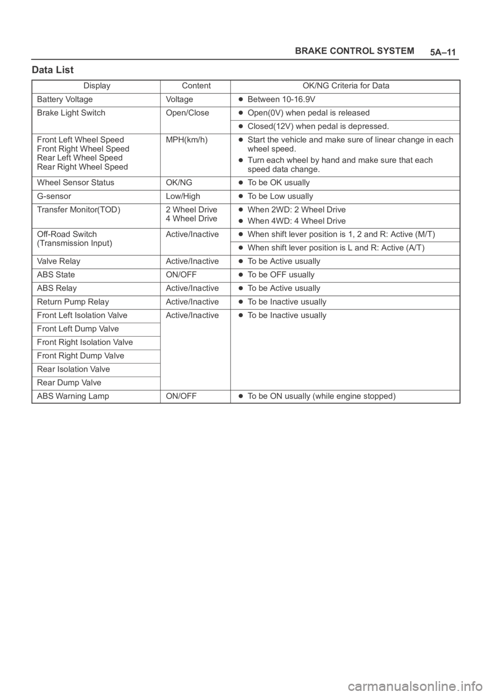
Data List
DisplayContentOK/NG Criteria for Data
Battery VoltageVo l t a g eBetween 10-16.9V
Brake Light SwitchOpen/CloseOpen(0V) when pedal is released
Closed(12V) when pedal is depressed.
Front Left Wheel Speed
Front Right Wheel Speed
Rear Left Wheel Speed
Rear Right Wheel SpeedMPH(km/h)Start the vehicle and make sure of linear change in each
wheel speed.
Turn each wheel by hand and make sure that each
speed data change.
Wheel Sensor StatusOK/NGTo be OK usually
G-sensorLow/HighTo be Low usually
Transfer Monitor(TOD)2 Wheel Drive
4 Wheel DriveWhen 2WD: 2 Wheel Drive
When 4WD: 4 Wheel Drive
Off-Road Switch
(Transmission Input)
Active/InactiveWhen shift lever position is 1, 2 and R: Active (M/T)
(Transmission Input)When shift lever position is L and R: Active (A/T)
Valve RelayActive/InactiveTo be Active usually
ABS StateON/OFFTo be OFF usually
ABS RelayActive/InactiveTo be Active usually
Return Pump RelayActive/InactiveTo be Inactive usually
Front Left Isolation ValveActive/InactiveTo be Inactive usually
Front Left Dump Valve
Front Right Isolation Valve
Front Right Dump Valve
Rear Isolation Valve
Rear Dump Valve
ABS Warning LampON/OFFTo be ON usually (while engine stopped)
Page 846 of 6000
5A–36
BRAKE CONTROL SYSTEM
StepNo Ye s
Action
10Is the input of 4WD controller normal?
Go to Step 11
Replace
controller or
repair harness.
Go to Step 11
11Reconnect all components and ensure all components are
properly mounted.
Was this step finished?Repeat the “Basic
diagnostic flow
chart.”
Go to Step 11
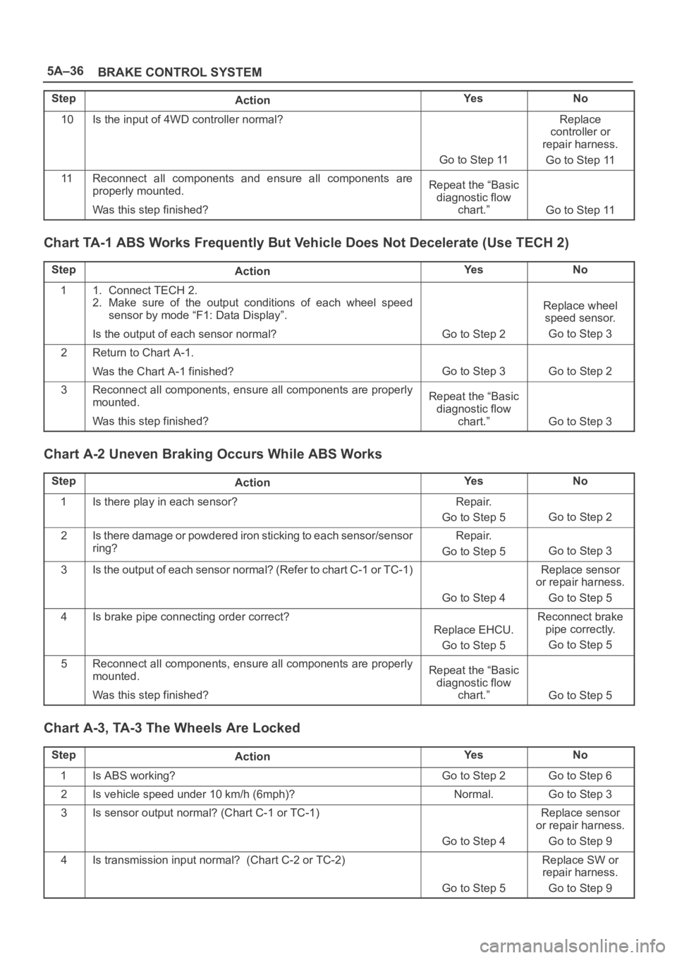
Chart TA-1 ABS Works Frequently But Vehicle Does Not Decelerate (Use TECH 2)
StepActionYe sNo
11. Connect TECH 2.
2. Make sure of the output conditions of each wheel speed
sensor by mode “F1: Data Display”.
Is the output of each sensor normal?
Go to Step 2
Replace wheel
speed sensor.
Go to Step 3
2Return to Chart A-1.
Was the Chart A-1 finished?
Go to Step 3Go to Step 2
3Reconnect all components, ensure all components are properly
mounted.
Was this step finished?Repeat the “Basic
diagnostic flow
chart.”
Go to Step 3
Chart A-2 Uneven Braking Occurs While ABS Works
StepActionYe sNo
1Is there play in each sensor?Repair.
Go to Step 5
Go to Step 2
2Is there damage or powdered iron sticking to each sensor/sensor
ring?Repair.
Go to Step 5
Go to Step 3
3Is the output of each sensor normal? (Refer to chart C-1 or TC-1)
Go to Step 4
Replace sensor
or repair harness.
Go to Step 5
4Is brake pipe connecting order correct?
Replace EHCU.
Go to Step 5
Reconnect brake
pipe correctly.
Go to Step 5
5Reconnect all components, ensure all components are properly
mounted.
Was this step finished?Repeat the “Basic
diagnostic flow
chart.”
Go to Step 5
Chart A-3, TA-3 The Wheels Are Locked
StepActionYe sNo
1Is ABS working?Go to Step 2Go to Step 6
2Is vehicle speed under 10 km/h (6mph)?Normal.Go to Step 3
3Is sensor output normal? (Chart C-1 or TC-1)
Go to Step 4
Replace sensor
or repair harness.
Go to Step 9
4Is transmission input normal? (Chart C-2 or TC-2)
Go to Step 5
Replace SW or
repair harness.
Go to Step 9
Page 847 of 6000
5A–37 BRAKE CONTROL SYSTEM
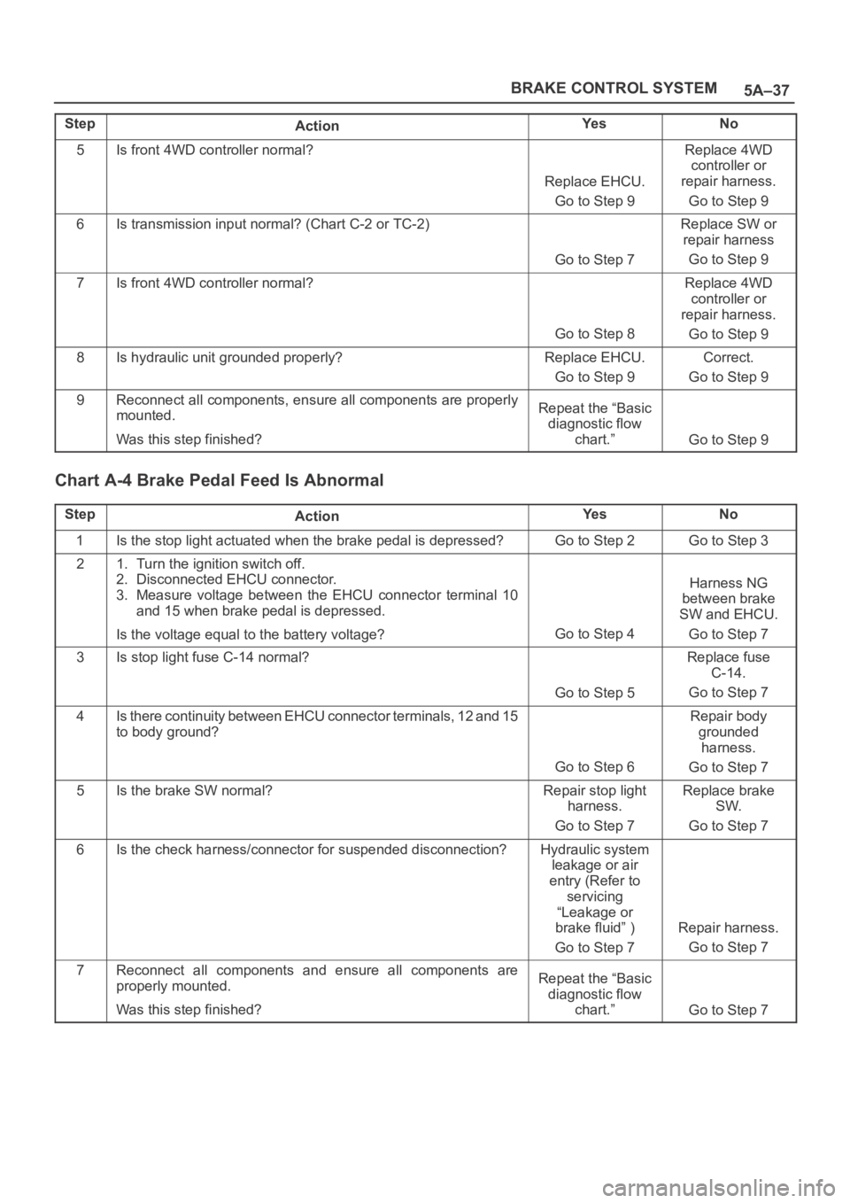
StepNo Ye s
Action
5Is front 4WD controller normal?
Replace EHCU.
Go to Step 9
Replace 4WD
controller or
repair harness.
Go to Step 9
6Is transmission input normal? (Chart C-2 or TC-2)
Go to Step 7
Replace SW or
repair harness
Go to Step 9
7Is front 4WD controller normal?
Go to Step 8
Replace 4WD
controller or
repair harness.
Go to Step 9
8Is hydraulic unit grounded properly?Replace EHCU.
Go to Step 9Correct.
Go to Step 9
9Reconnect all components, ensure all components are properly
mounted.
Was this step finished?Repeat the “Basic
diagnostic flow
chart.”
Go to Step 9
Chart A-4 Brake Pedal Feed Is Abnormal
StepActionYe sNo
1Is the stop light actuated when the brake pedal is depressed?Go to Step 2Go to Step 3
21. Turn the ignition switch off.
2. Disconnected EHCU connector.
3. Measure voltage between the EHCU connector terminal 10
and 15 when brake pedal is depressed.
Is the voltage equal to the battery voltage?
Go to Step 4
Harness NG
between brake
SW and EHCU.
Go to Step 7
3Is stop light fuse C-14 normal?
Go to Step 5
Replace fuse
C-14.
Go to Step 7
4Is there continuity between EHCU connector terminals, 12 and 15
to body ground?
Go to Step 6
Repair body
grounded
harness.
Go to Step 7
5Is the brake SW normal?Repair stop light
harness.
Go to Step 7Replace brake
SW.
Go to Step 7
6Is the check harness/connector for suspended disconnection?Hydraulic system
leakage or air
entry (Refer to
servicing
“Leakage or
brake fluid” )
Go to Step 7
Repair harness.
Go to Step 7
7Reconnect all components and ensure all components are
properly mounted.
Was this step finished?Repeat the “Basic
diagnostic flow
chart.”
Go to Step 7
Page 857 of 6000
5A–47 BRAKE CONTROL SYSTEM
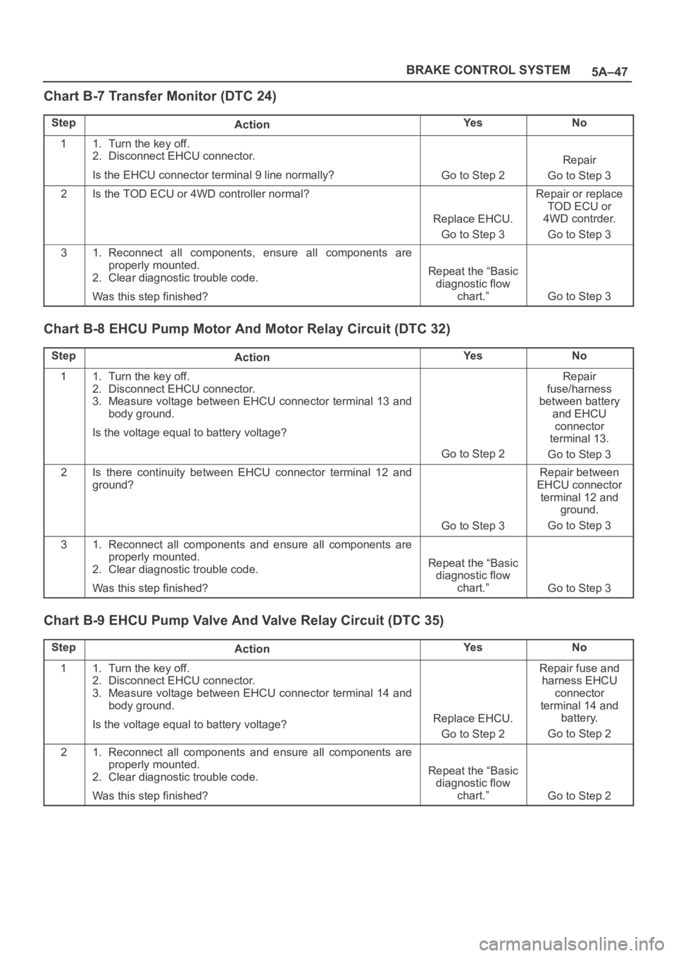
Chart B-7 Transfer Monitor (DTC 24)
StepActionYe sNo
11. Turn the key off.
2. Disconnect EHCU connector.
Is the EHCU connector terminal 9 line normally?
Go to Step 2
Repair
Go to Step 3
2Is the TOD ECU or 4WD controller normal?
Replace EHCU.
Go to Step 3
Repair or replace
TOD ECU or
4WD contrder.
Go to Step 3
31. Reconnect all components, ensure all components are
properly mounted.
2. Clear diagnostic trouble code.
Was this step finished?
Repeat the “Basic
diagnostic flow
chart.”
Go to Step 3
Chart B-8 EHCU Pump Motor And Motor Relay Circuit (DTC 32)
StepActionYe sNo
11. Turn the key off.
2. Disconnect EHCU connector.
3. Measure voltage between EHCU connector terminal 13 and
body ground.
Is the voltage equal to battery voltage?
Go to Step 2
Repair
fuse/harness
between battery
and EHCU
connector
terminal 13.
Go to Step 3
2Is there continuity between EHCU connector terminal 12 and
ground?
Go to Step 3
Repair between
EHCU connector
terminal 12 and
ground.
Go to Step 3
31. Reconnect all components and ensure all components are
properly mounted.
2. Clear diagnostic trouble code.
Was this step finished?
Repeat the “Basic
diagnostic flow
chart.”
Go to Step 3
Chart B-9 EHCU Pump Valve And Valve Relay Circuit (DTC 35)
StepActionYe sNo
11. Turn the key off.
2. Disconnect EHCU connector.
3. Measure voltage between EHCU connector terminal 14 and
body ground.
Is the voltage equal to battery voltage?
Replace EHCU.
Go to Step 2
Repair fuse and
harness EHCU
connector
terminal 14 and
battery.
Go to Step 2
21. Reconnect all components and ensure all components are
properly mounted.
2. Clear diagnostic trouble code.
Was this step finished?
Repeat the “Basic
diagnostic flow
chart.”
Go to Step 2
Page 1149 of 6000
6E–32
ENGINE DRIVEABILITY AND EMISSIONS
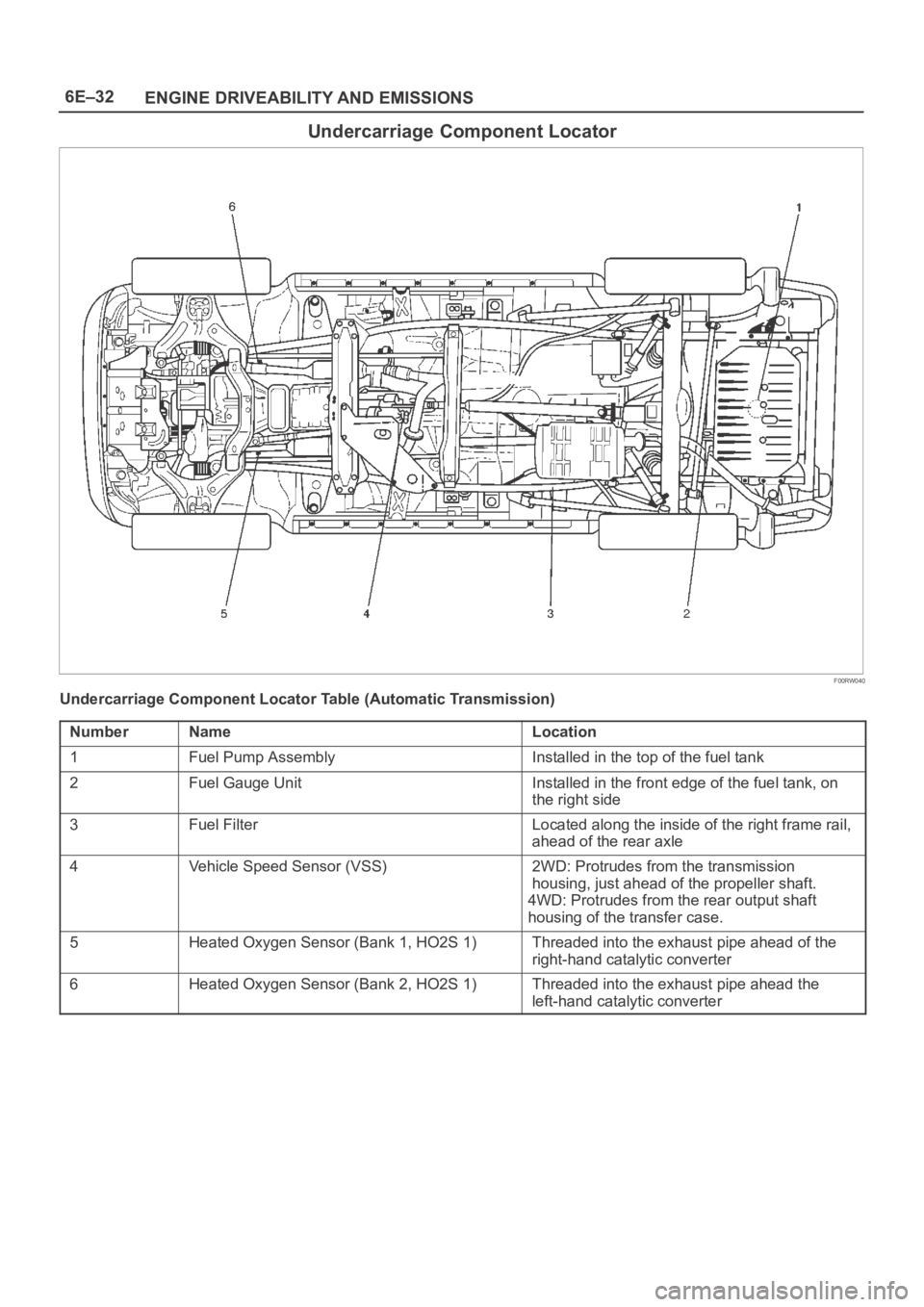
Undercarriage Component Locator
F00RW040
Undercarriage Component Locator Table (Automatic Transmission)
Number
NameLocation
1Fuel Pump AssemblyInstalled in the top of the fuel tank
2Fuel Gauge UnitInstalled in the front edge of the fuel tank, on
the right side
3Fuel FilterLocated along the inside of the right frame rail,
ahead of the rear axle
4Vehicle Speed Sensor (VSS)2WD: Protrudes from the transmission
housing, just ahead of the propeller shaft.
4WD: Protrudes from the rear output shaft
housing of the transfer case.
5Heated Oxygen Sensor (Bank 1, HO2S 1)Threaded into the exhaust pipe ahead of the
right-hand catalytic converter
6Heated Oxygen Sensor (Bank 2, HO2S 1)Threaded into the exhaust pipe ahead the
left-hand catalytic converter
Page 1150 of 6000
6E–33 ENGINE DRIVEABILITY AND EMISSIONS
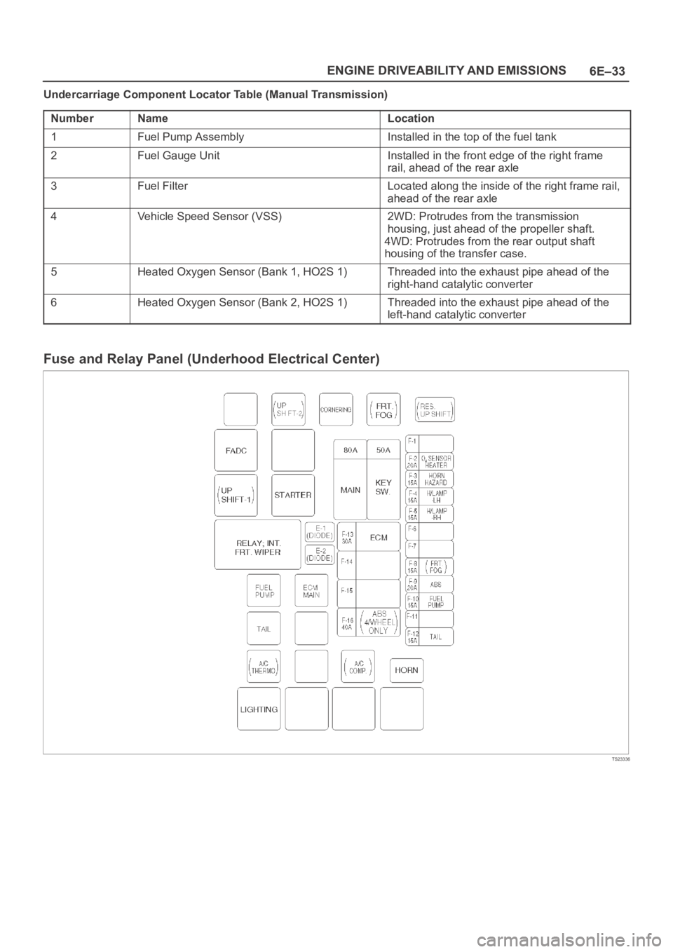
Undercarriage Component Locator Table (Manual Transmission)
Number
NameLocation
1Fuel Pump AssemblyInstalled in the top of the fuel tank
2Fuel Gauge UnitInstalled in the front edge of the right frame
rail, ahead of the rear axle
3Fuel FilterLocated along the inside of the right frame rail,
ahead of the rear axle
4Vehicle Speed Sensor (VSS)2WD: Protrudes from the transmission
housing, just ahead of the propeller shaft.
4WD: Protrudes from the rear output shaft
housing of the transfer case.
5Heated Oxygen Sensor (Bank 1, HO2S 1)Threaded into the exhaust pipe ahead of the
right-hand catalytic converter
6Heated Oxygen Sensor (Bank 2, HO2S 1)Threaded into the exhaust pipe ahead of the
left-hand catalytic converter
Fuse and Relay Panel (Underhood Electrical Center)
TS23336
Page 2173 of 6000
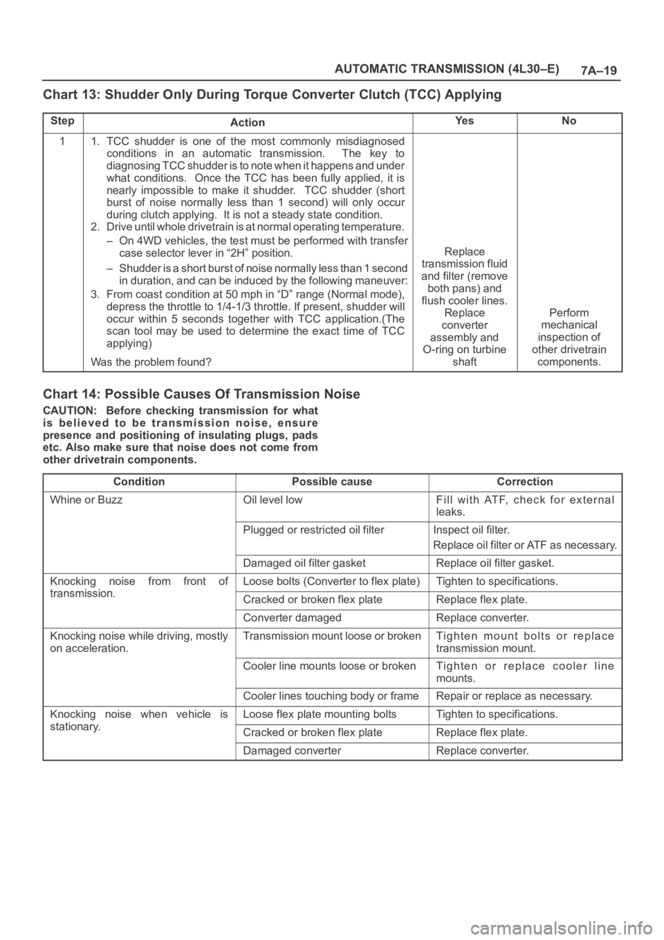
7A–19 AUTOMATIC TRANSMISSION (4L30–E)
Chart 13: Shudder Only During Torque Converter Clutch (TCC) Applying
StepActionYe sNo
11. TCC shudder is one of the most commonly misdiagnosed
conditions in an automatic transmission. The key to
diagnosing TCC shudder is to note when it happens and under
what conditions. Once the TCC has been fully applied, it is
nearly impossible to make it shudder. TCC shudder (short
burst of noise normally less than 1 second) will only occur
during clutch applying. It is not a steady state condition.
2. Drive until whole drivetrain is at normal operating temperature.
– On 4WD vehicles, the test must be performed with transfer
case selector lever in “2H” position.
– Shudder is a short burst of noise normally less than 1 second
in duration, and can be induced by the following maneuver:
3. From coast condition at 50 mph in “D” range (Normal mode),
depress the throttle to 1/4-1/3 throttle. If present, shudder will
occur within 5 seconds together with TCC application.(The
scan tool may be used to determine the exact time of TCC
applying)
Was the problem found?
Replace
transmission fluid
and filter (remove
both pans) and
flush cooler lines.
Replace
converter
assembly and
O-ring on turbine
shaft
Perform
mechanical
inspection of
other drivetrain
components.
Chart 14: Possible Causes Of Transmission Noise
CAUTION: Before checking transmission for what
is believed to be transmission noise, ensure
presence and positioning of insulating plugs, pads
etc. Also make sure that noise does not come from
other drivetrain components.
Condition
Possible causeCorrection
Whine or BuzzOil level lowFill with ATF, check for external
leaks.
Plugged or restricted oil filterInspect oil filter.
Replace oil filter or ATF as necessary.
Damaged oil filter gasketReplace oil filter gasket.
Knocking noise from front of
transmission
Loose bolts (Converter to flex plate)Tighten to specifications.
transmission.Cracked or broken flex plateReplace flex plate.
Converter damagedReplace converter.
Knocking noise while driving, mostly
on acceleration.Transmission mount loose or brokenTighten mount bolts or replace
transmission mount.
Cooler line mounts loose or brokenTighten or replace cooler line
mounts.
Cooler lines touching body or frameRepair or replace as necessary.
Knocking noise when vehicle is
stationary
Loose flex plate mounting boltsTighten to specifications.
stationary.Cracked or broken flex plateReplace flex plate.
Damaged converterReplace converter.