immobilizer OPEL FRONTERA 1998 Repair Manual
[x] Cancel search | Manufacturer: OPEL, Model Year: 1998, Model line: FRONTERA, Model: OPEL FRONTERA 1998Pages: 6000, PDF Size: 97 MB
Page 1456 of 6000

6E–339 ENGINE DRIVEABILITY AND EMISSIONS
0005
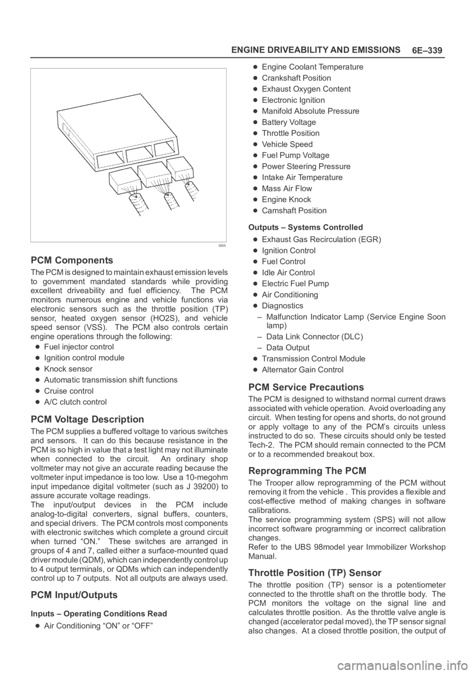
PCM Components
The PCM is designed to maintain exhaust emission levels
to government mandated standards while providing
excellent driveability and fuel efficiency. The PCM
monitors numerous engine and vehicle functions via
electronic sensors such as the throttle position (TP)
sensor, heated oxygen sensor (HO2S), and vehicle
speed sensor (VSS). The PCM also controls certain
engine operations through the following:
Fuel injector control
Ignition control module
Knock sensor
Automatic transmission shift functions
Cruise control
A/C clutch control
PCM Voltage Description
The PCM supplies a buffered voltage to various switches
and sensors. It can do this because resistance in the
PCM is so high in value that a test light may not illuminate
when connected to the circuit. An ordinary shop
voltmeter may not give an accurate reading because the
voltmeter input impedance is too low. Use a 10-megohm
input impedance digital voltmeter (such as J 39200) to
assure accurate voltage readings.
The input/output devices in the PCM include
analog-to-digital converters, signal buffers, counters,
and special drivers. The PCM controls most components
with electronic switches which complete a ground circuit
when turned “ON.” These switches are arranged in
groups of 4 and 7, called either a surface-mounted quad
driver module (QDM), which can independently control up
to 4 output terminals, or QDMs which can independently
control up to 7 outputs. Not all outputs are always used.
PCM Input/Outputs
Inputs – Operating Conditions Read
Air Conditioning “ON” or “OFF”
Engine Coolant Temperature
Crankshaft Position
Exhaust Oxygen Content
Electronic Ignition
Manifold Absolute Pressure
Battery Voltage
Throttle Position
Vehicle Speed
Fuel Pump Voltage
Power Steering Pressure
Intake Air Temperature
Mass Air Flow
Engine Knock
Camshaft Position
Outputs – Systems Controlled
Exhaust Gas Recirculation (EGR)
Ignition Control
Fuel Control
Idle Air Control
Electric Fuel Pump
Air Conditioning
Diagnostics
– Malfunction Indicator Lamp (Service Engine Soon
lamp)
– Data Link Connector (DLC)
– Data Output
Transmission Control Module
Alternator Gain Control
PCM Service Precautions
The PCM is designed to withstand normal current draws
associated with vehicle operation. Avoid overloading any
circuit. When testing for opens and shorts, do not ground
or apply voltage to any of the PCM’s circuits unless
instructed to do so. These circuits should only be tested
Tech-2. The PCM should remain connected to the PCM
or to a recommended breakout box.
Reprogramming The PCM
The Trooper allow reprogramming of the PCM without
removing it from the vehicle . This provides a flexible and
cost-effective method of making changes in software
calibrations.
The service programming system (SPS) will not allow
incorrect software programming or incorrect calibration
changes.
Refer to the UBS 98model year Immobilizer Workshop
Manual.
Throttle Position (TP) Sensor
The throttle position (TP) sensor is a potentiometer
connected to the throttle shaft on the throttle body. The
PCM monitors the voltage on the signal line and
calculates throttle position. As the throttle valve angle is
changed (accelerator pedal moved), the TP sensor signal
also changes. At a closed throttle position, the output of
Page 1873 of 6000

6D – 6 ENGINE ELECTRICAL
RELATION BETWEEN STARTER SWITCH AND STARTER
M
Key
PositionB1 B2 ACCIG1 IG2 ST
LOCKKey
Removed
Inserted OFF
ACC
ON
START
BSBattery
+-
2
17
3
4
5
6
Legend
(1) Starter Switch
(2) To Generator
(3) To QOS4 Control(4) Starter Relay
(5) Immobilizer Relay (for Europe)
(6) Magnetic Switch
(7) Battery
065R200029
Page 1948 of 6000

6E–55 4JX1–TC ENGINE DRIVEABILITY AND EMISSIONS
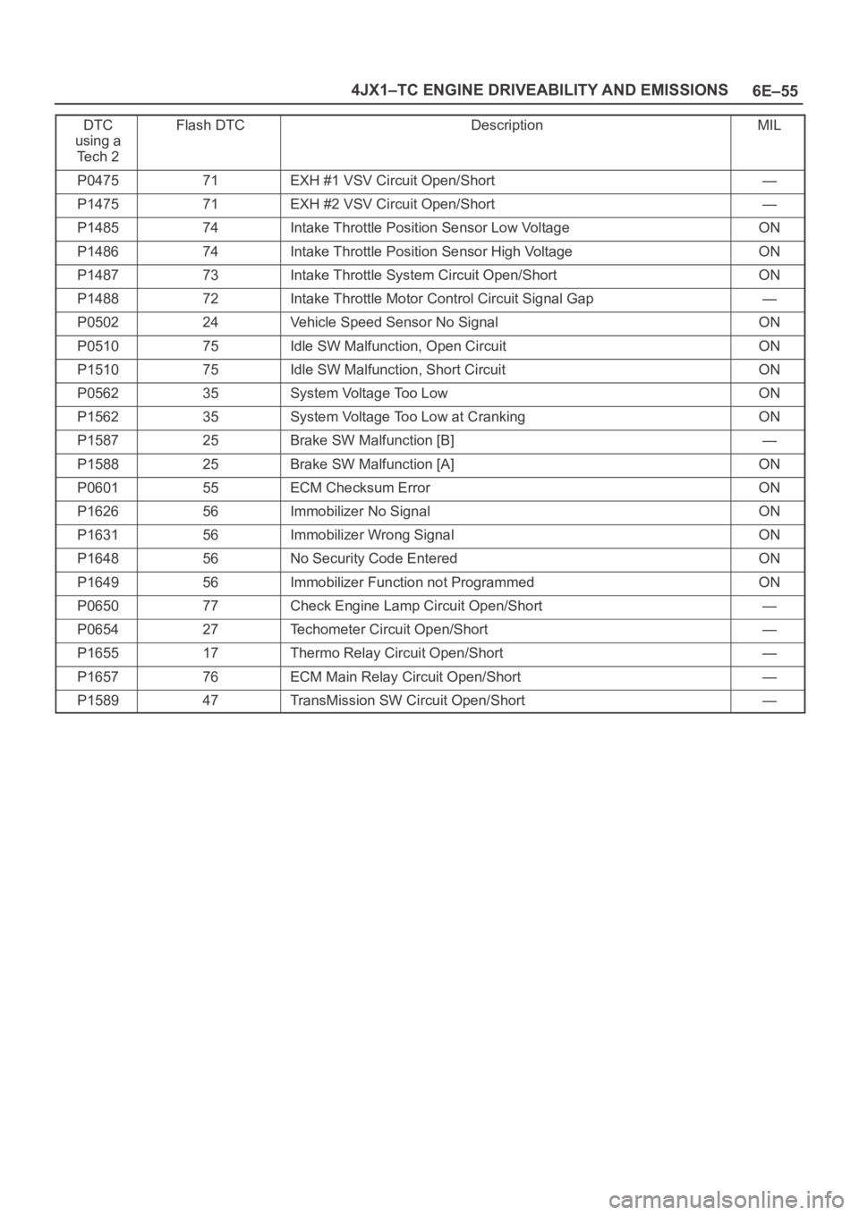
DTC
using a
Te c h 2Flash DTCDescriptionMIL
P047571EXH #1 VSV Circuit Open/Short—
P147571EXH #2 VSV Circuit Open/Short—
P148574Intake Throttle Position Sensor Low VoltageON
P148674Intake Throttle Position Sensor High VoltageON
P148773Intake Throttle System Circuit Open/ShortON
P148872Intake Throttle Motor Control Circuit Signal Gap—
P050224Vehicle Speed Sensor No SignalON
P051075Idle SW Malfunction, Open CircuitON
P151075Idle SW Malfunction, Short CircuitON
P056235System Voltage Too LowON
P156235System Voltage Too Low at CrankingON
P158725Brake SW Malfunction [B]—
P158825Brake SW Malfunction [A]ON
P060155ECM Checksum ErrorON
P162656Immobilizer No SignalON
P163156Immobilizer Wrong SignalON
P164856No Security Code EnteredON
P164956Immobilizer Function not ProgrammedON
P065077Check Engine Lamp Circuit Open/Short—
P065427Techometer Circuit Open/Short—
P165517Thermo Relay Circuit Open/Short—
P165776ECM Main Relay Circuit Open/Short—
P158947TransMission SW Circuit Open/Short—
Page 2662 of 6000

B-22B-36
22
H-1512
17 B-22
B-19 1.25
B2.0
B 0.5
B
ANTI-THEFT & KEYLESS
ENTRY CONTROL UNITHEATER &
A/C RELAY
STARTER
(W/O ANTI-THEFT)IMMOBILIZER
CONTROL UNIT
(10)
0.85
B0.5
L/B0.5
G/Y 0.5
L 0.5
L
0.5
L/B
BODY-RH
B-2
BODY-LHB-18
BODY-RHB-19
BODY-RH
B-36
B-36
3.0
L/R5.0
W
0.3
B 0.85
W/R
3.0
B/W 30.0
B/R
C-19 25A
BLOWER
BLOWER
MOTORPRESSURE SW
(A/C)C-20 10A
AIR CON B-3612
1
34
BATT.(+) FUSE
C-8
1.25
B3.0
W
P-4
P-3
X-20IMMOBILIZER
RELAYX-20
X-20 X-2021
43
0.5
B/Y
D08RW586
Page 3572 of 6000

PA G E B A C K
THIS MALUAL INCLUDES THE FOLLOWING SECTIONS:
SECTION No. CONTRNTS
Sec.- IMMOBILIZER SYSTEM
HOME
-
Page 4709 of 6000

6E–52
ENGINE DRIVEABILITY AND EMISSIONS
10.This vehicle is equipped with a PCM which utilizes
an electrically erasable programmable read only
memory (EEPROM). When the PCM is replaced,
the new PCM must be programmed.
Refer to UBS
98 model year Immobilizer Workshop Manual.
Page 4714 of 6000

6E–57 ENGINE DRIVEABILITY AND EMISSIONS
A/C Clutch Control Circuit Diagnosis
StepNo Ye s Va l u e ( s ) Action
19Replace the A/C switch.
Is the action complete?
—Verify repair—
20Use an ohmmeter to check continuity between the
electronic A/C thermostat and the blower switch.
Was there an open circuit?
—Go to Step 21Go to Step 22
21Repair the open wire (GRN/YEL) between the
thermostat and the blower switch.
Is the action complete?
—Verify repair—
22Replace the electronic A/C thermostat.
Is the an action complete?
—Verify repair—
23Check for an open circuit between A/C thermostat relay
and PCM A/C request terminal (E-15).
Was there an open circuit?
—Go to Step 24Go to Step 25
24Repair the open circuit between the PCM and A/C
thermostat relay.
Is the action complete?
—Verify repair—
25Check for an open circuit between the A/C switch (LT
GRN) and the A/C thermostat relay (LT GRN).
Was there an open circuit?
—Go to Step 26Go to Step 27
26Repair the open circuit between the A/C switch and the
A/C thermostat relay.
Is the action complete?
—Verify repair—
271. Ignition “ON.”
2. Use a DVM to check voltage at the A/C pressure
switch (BRN).
Was voltage equal to the specified value?
+BGo to Step 29Go to Step 28
28Repair the open circuit between the 10A A/C fuse and
the pressure switch.
Is the action complete?
—Verify repair—
29Use an ohmmeter to check continuity between the
pressure switch (GRN/WHT) and the A/C thermostat
relay (GRN/WHT).
Was the circuit open?
—Go to Step 30Go to Step 31
30Repair the open circuit between the pressure switch
and the A/C thermostat relay.
Is the action complete?
—Verify repair—
31Check for damaged pin or terminal at E-15 of the PCM.
Was a damaged pin or terminal found?
—Go to Step 32Go to Step 33
32Repair the damaged pin or terminal.
Is the action complete?
—Verify repair—
33Replace the PCM.
IMPORTANT:The replacement PCM must be
programmed. Refer to
UBS 98model year Immobilizer
Workshop Manual.
Is the action complete?—Verify repair—
Page 4724 of 6000

6E–67 ENGINE DRIVEABILITY AND EMISSIONS
Multiple PCM Information Sensor DTCs Set
StepNo Ye s Va l u e ( s ) Action
111. Disconnect the EGR valve.
2. Measure the voltage between the EGR pintle
position sensor signal circuit at the PCM harness
connector and ground.
Does the voltage measure near the specified value?
0 VGo to Step 13Go to Step 18
12Measure the voltage between the TFT sensor signal
circuit at the PCM harness connector and ground.
Does the voltage measure near the specified value?
0 VGo to Step 20Go to Step 19
13Replace the EGR valve.
Is the action complete?
—Verify repair—
14Locate and repair the short to voltage in the MAP
sensor signal circuit.
Is the action complete?
—Verify repair—
15Locate and repair the short to voltage in the TP sensor
signal circuit.
Is the action complete?
—Verify repair—
16Locate and repair the short to voltage in the IAT sensor
signal circuit.
Is the action complete?
—Verify repair—
17Locate and repair the short to voltage in the ECT
sensor signal circuit.
Is the action complete?
—Verify repair—
18Locate and repair the short to voltage in the EGR pintle
position sensor signal circuit.
Is the action complete?
—Verify repair—
19Locate and repair the short to voltage in the TFT sensor
signal circuit.
Is the action complete?
—Verify repair—
20Replace the PCM.
IMPORTANT:The replacement PCM must be
programmed. Refer to
UBS 98model year Immobilizer
Workshop Manual.
Is the action complete?—
Go to OBD
System
Check
—
Page 4732 of 6000

6E–75 ENGINE DRIVEABILITY AND EMISSIONS
17.This vehicle is equipped with a PCM which utilizes
an electrically erasable programmable read only
memory (EEPROM). When the PCM is replaced,
the new PCM must be programmed. Refer to
UBS
98 model year Immobilizer Workshop Manual.
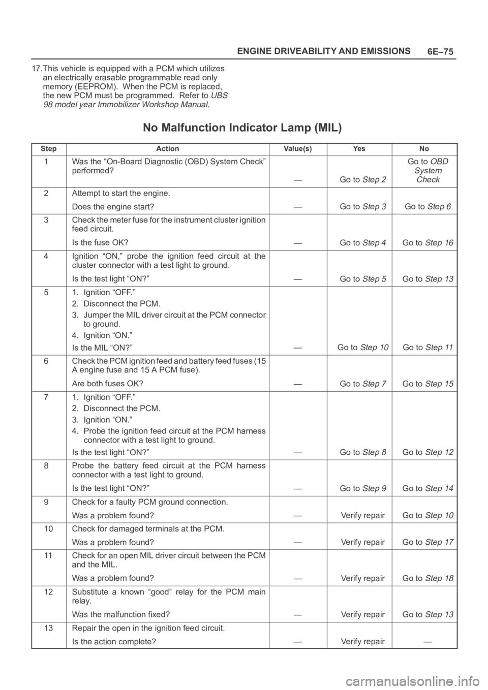
No Malfunction Indicator Lamp (MIL)
StepActionVa l u e ( s )Ye sNo
1Was the “On-Board Diagnostic (OBD) System Check”
performed?
—Go to Step 2
Go to OBD
System
Check
2Attempt to start the engine.
Does the engine start?
—Go to Step 3Go to Step 6
3Check the meter fuse for the instrument cluster ignition
feed circuit.
Is the fuse OK?
—Go to Step 4Go to Step 16
4Ignition “ON,” probe the ignition feed circuit at the
cluster connector with a test light to ground.
Is the test light “ON?”
—Go to Step 5Go to Step 13
51. Ignition “OFF.”
2. Disconnect the PCM.
3. Jumper the MIL driver circuit at the PCM connector
to ground.
4. Ignition “ON.”
Is the MIL “ON?”
—Go to Step 10Go to Step 11
6Check the PCM ignition feed and battery feed fuses (15
A engine fuse and 15 A PCM fuse).
Are both fuses OK?
—Go to Step 7Go to Step 15
71. Ignition “OFF.”
2. Disconnect the PCM.
3. Ignition “ON.”
4. Probe the ignition feed circuit at the PCM harness
connector with a test light to ground.
Is the test light “ON?”
—Go to Step 8Go to Step 12
8Probe the battery feed circuit at the PCM harness
connector with a test light to ground.
Is the test light “ON?”
—Go to Step 9Go to Step 14
9Check for a faulty PCM ground connection.
Was a problem found?
—Verify repairGo to Step 10
10Check for damaged terminals at the PCM.
Was a problem found?
—Verify repairGo to Step 17
11Check for an open MIL driver circuit between the PCM
and the MIL.
Was a problem found?
—Verify repairGo to Step 18
12Substitute a known “good” relay for the PCM main
relay.
Was the malfunction fixed?
—Verify repairGo to Step 13
13Repair the open in the ignition feed circuit.
Is the action complete?
—Verify repair—
Page 4734 of 6000

6E–77 ENGINE DRIVEABILITY AND EMISSIONS
Malfunction Indicator Lamp (MIL) “ON” Steady
D06RW00007
Circuit description
The malfunction indicator lamp (MIL) should always be
illuminated and steady with ignition “ON” and the engine
stopped. Ignition feed voltage is supplied directly to the
MIL indicator. The powertrain control module (PCM)
turns the MIL “ON” by grounding the MIL driver circuit.
The MIL should not remain “ON” with the engine running
and no DTC(s) set. A steady MIL with the engine running
and no DTC(s) suggests a short to ground in the MIL
driver circuit.
Diagnostic Aids
An intermittent may be caused by a poor connection,
rubbed-through wire insulation, or a wire broken inside
the insulation. Check for the following items:
Poor connection or damaged harness – Inspect the
PCM harness and connectors for improper mating,
broken locks, improperly formed or damaged
terminals, poor terminal-to-wire connection, and
damaged harness.
Test Description
Number(s) below refer to the step number(s) on the
Diagnostic Chart.
2. If the MIL does not remain “ON” when the PCM is
disconnected, the MIL driver wiring is not faulty.
3. If the MIL driver circuit is OK, the instrument panel
cluster is faulty.
6. This vehicle is equipped with a PCM which utilizes
an electrically erasable programmable read only
memory (EEPROM). When the PCM is replaced,
the new PCM must be programmed. Refer to
UBS
98 model year Immobilizer Workshop Manual.