cooling OPEL FRONTERA 1998 Workshop Manual
[x] Cancel search | Manufacturer: OPEL, Model Year: 1998, Model line: FRONTERA, Model: OPEL FRONTERA 1998Pages: 6000, PDF Size: 97 MB
Page 9 of 6000
PAGE BACK PAGE NEXT
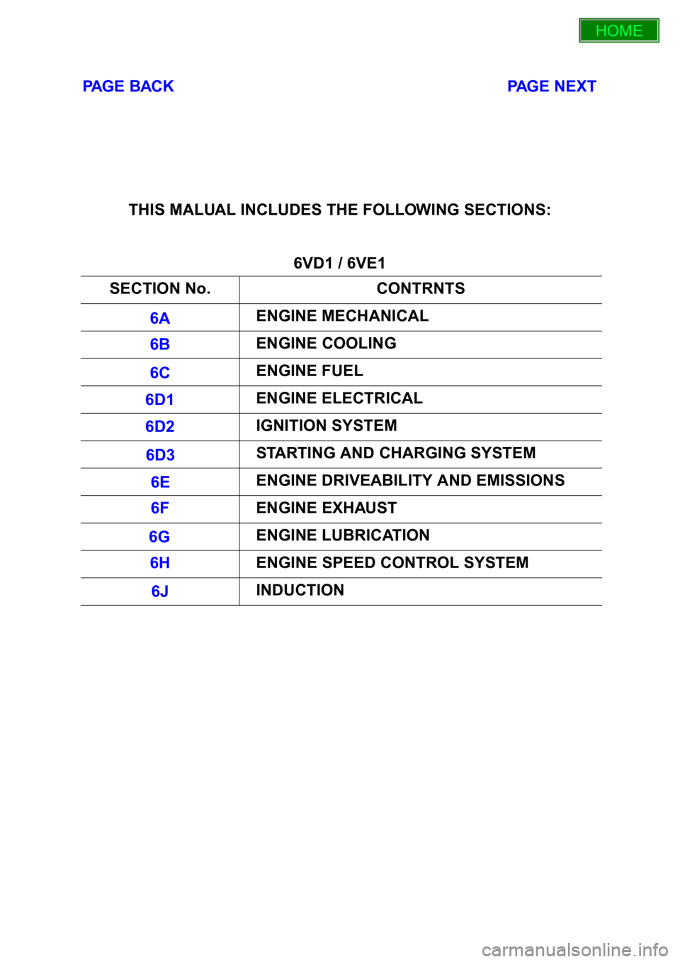
THIS MALUAL INCLUDES THE FOLLOWING SECTIONS:
6VD1 / 6VE1
SECTION No. CONTRNTS
6A ENGINE MECHANICAL
6B ENGINE COOLING
6C ENGINE FUEL
6D1 ENGINE ELECTRICAL
6D2 IGNITION SYSTEM
6D3 STARTING AND CHARGING SYSTEM
6E ENGINE DRIVEABILITY AND EMISSIONS
6F ENGINE EXHAUST
6G ENGINE LUBRICATION
6H ENGINE SPEED CONTROL SYSTEM
6J INDUCTION
HOME
6A
6B
6C
6D1
6D2
6D3
6E
6F
6G
6H
6J
Page 10 of 6000
PAGE BACK PAGE NEXT
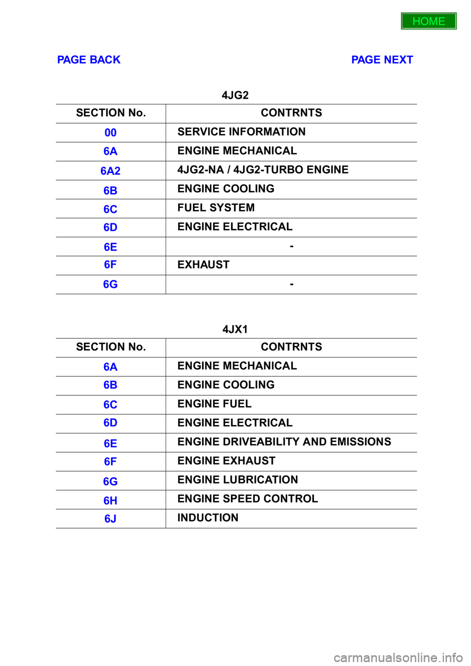
4JG2
4JX1 SECTION No. CONTRNTS
00 SERVICE INFORMATION
6A ENGINE MECHANICAL
6A2 4JG2-NA / 4JG2-TURBO ENGINE
6B ENGINE COOLING
6C FUEL SYSTEM
6D ENGINE ELECTRICAL
6E -
6F EXHAUST
6G -
SECTION No. CONTRNTS
6A ENGINE MECHANICAL
6B ENGINE COOLING
6C ENGINE FUEL
6D ENGINE ELECTRICAL
6E ENGINE DRIVEABILITY AND EMISSIONS
6F ENGINE EXHAUST
6G ENGINE LUBRICATION
6H ENGINE SPEED CONTROL
6J INDUCTION
HOME
00
6A
6A2
6B
6C
6D
6E
6F
6G
6A
6B
6C
6D
6E
6F
6G
6H
6J
Page 217 of 6000
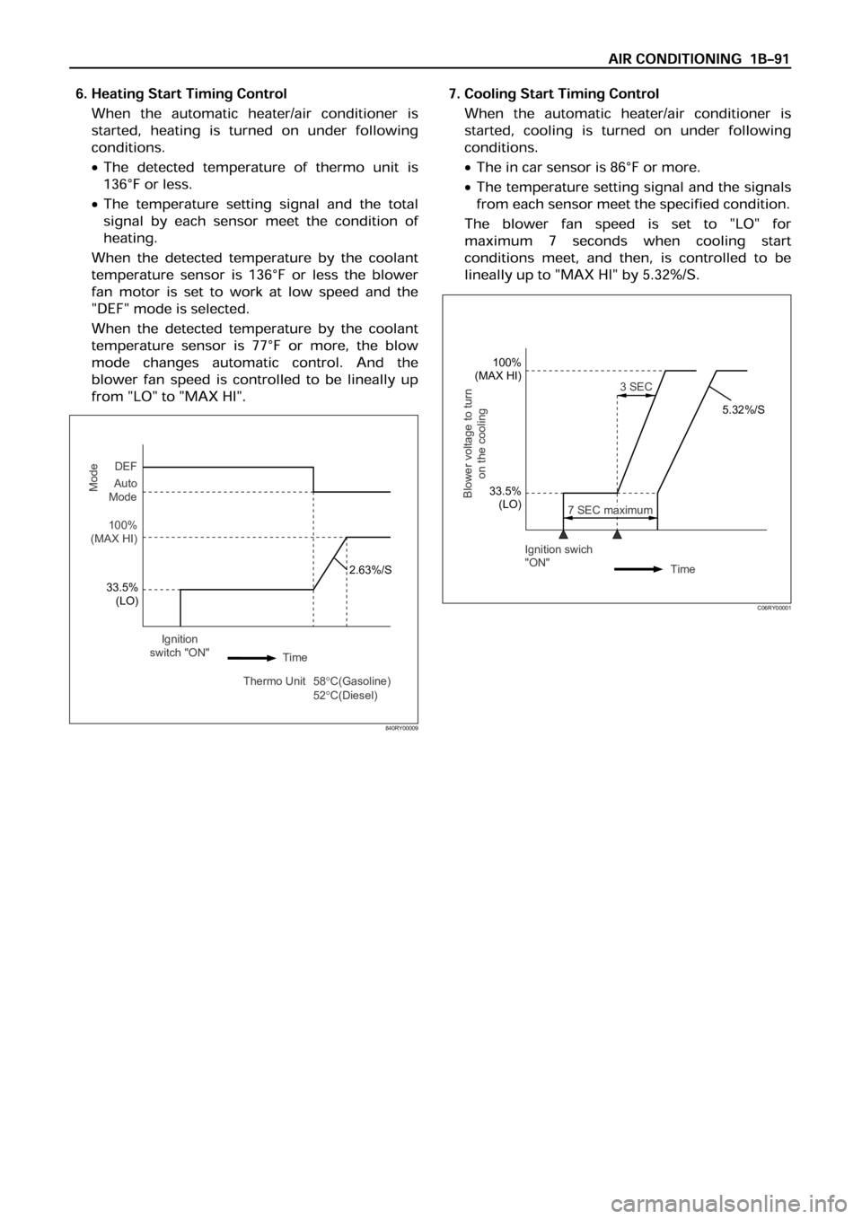
Ignition swich
"ON"
Time
Blower voltage to turn
on the cooling
7 SEC maximum3 SEC
100%
(MAX HI)
33.5%
(LO)5.32%/S
C06RY00001
33.5%
(LO)
2.63%/S
Mode
DEF
Auto
Mode
100%
(MAX HI)
Ignition
switch "ON"
Thermo Unit 58
C(Gasoline)
52C(Diesel) Time
840RY00009
Page 218 of 6000

Occurrence of a trouble
Refer to the check list for
the inspection.Locate the failed location.
Check the failed part.
Correction
Correction
Correction
Troubleshooting by the
self-diagnosis function.Reference the "Check
Procedure by Failed
Location" for the inspection.
Reference the "Check
Procedure by Failed
Location" for the inspection.Correction
Check the cooling / heating
cycles.
End OK OK OK OKNG
NG
NG
NG
NG OK
Check if the automatic
heater / air conditioner
control unit indicator LED
is turned on.Check the power supply and
circuit on the automatic
heater / air conditioner control
unit.
Troubleshooting not relying
on the self-diagnosis
function(troubleshooting
by failure type).
F01RX009
Page 957 of 6000
6A–1
ENGINE MECHANICAL
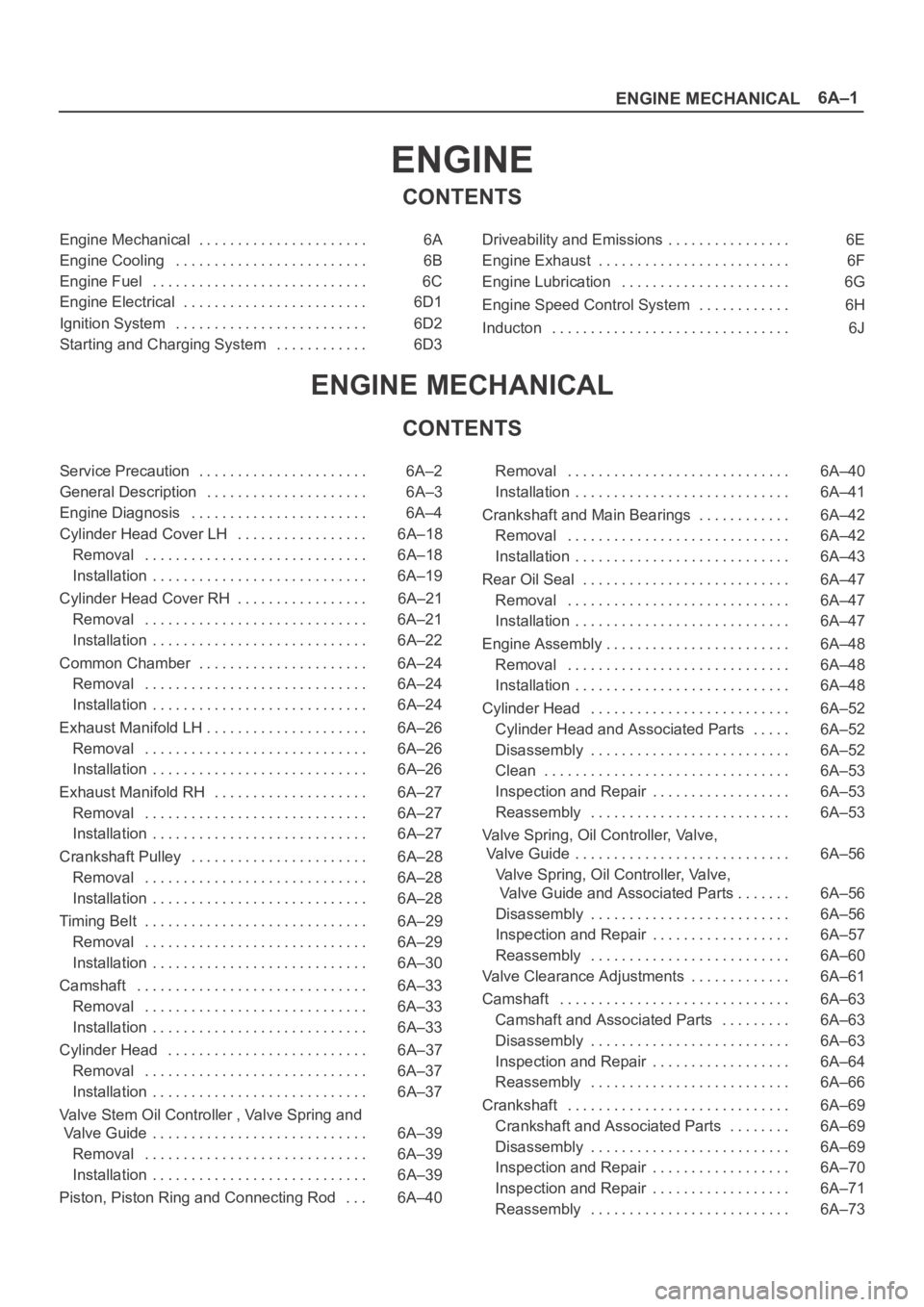
ENGINE
CONTENTS
Engine Mechanical 6A. . . . . . . . . . . . . . . . . . . . . .
Engine Cooling 6B. . . . . . . . . . . . . . . . . . . . . . . . .
Engine Fuel 6C. . . . . . . . . . . . . . . . . . . . . . . . . . . .
Engine Electrical 6D1. . . . . . . . . . . . . . . . . . . . . . . .
Ignition System 6D2. . . . . . . . . . . . . . . . . . . . . . . . .
Starting and Charging System 6D3. . . . . . . . . . . . Driveability and Emissions 6E. . . . . . . . . . . . . . . .
Engine Exhaust 6F. . . . . . . . . . . . . . . . . . . . . . . . .
Engine Lubrication 6G. . . . . . . . . . . . . . . . . . . . . .
Engine Speed Control System 6H. . . . . . . . . . . .
Inducton 6J. . . . . . . . . . . . . . . . . . . . . . . . . . . . . . .
ENGINE MECHANICAL
CONTENTS
Service Precaution 6A–2. . . . . . . . . . . . . . . . . . . . . .
General Description 6A–3. . . . . . . . . . . . . . . . . . . . .
Engine Diagnosis 6A–4. . . . . . . . . . . . . . . . . . . . . . .
Cylinder Head Cover LH 6A–18. . . . . . . . . . . . . . . . .
Removal 6A–18. . . . . . . . . . . . . . . . . . . . . . . . . . . . .
Installation 6A–19. . . . . . . . . . . . . . . . . . . . . . . . . . . .
Cylinder Head Cover RH 6A–21. . . . . . . . . . . . . . . . .
Removal 6A–21. . . . . . . . . . . . . . . . . . . . . . . . . . . . .
Installation 6A–22. . . . . . . . . . . . . . . . . . . . . . . . . . . .
Common Chamber 6A–24. . . . . . . . . . . . . . . . . . . . . .
Removal 6A–24. . . . . . . . . . . . . . . . . . . . . . . . . . . . .
Installation 6A–24. . . . . . . . . . . . . . . . . . . . . . . . . . . .
Exhaust Manifold LH 6A–26. . . . . . . . . . . . . . . . . . . . .
Removal 6A–26. . . . . . . . . . . . . . . . . . . . . . . . . . . . .
Installation 6A–26. . . . . . . . . . . . . . . . . . . . . . . . . . . .
Exhaust Manifold RH 6A–27. . . . . . . . . . . . . . . . . . . .
Removal 6A–27. . . . . . . . . . . . . . . . . . . . . . . . . . . . .
Installation 6A–27. . . . . . . . . . . . . . . . . . . . . . . . . . . .
Crankshaft Pulley 6A–28. . . . . . . . . . . . . . . . . . . . . . .
Removal 6A–28. . . . . . . . . . . . . . . . . . . . . . . . . . . . .
Installation 6A–28. . . . . . . . . . . . . . . . . . . . . . . . . . . .
Timing Belt 6A–29. . . . . . . . . . . . . . . . . . . . . . . . . . . . .
Removal 6A–29. . . . . . . . . . . . . . . . . . . . . . . . . . . . .
Installation 6A–30. . . . . . . . . . . . . . . . . . . . . . . . . . . .
Camshaft 6A–33. . . . . . . . . . . . . . . . . . . . . . . . . . . . . .
Removal 6A–33. . . . . . . . . . . . . . . . . . . . . . . . . . . . .
Installation 6A–33. . . . . . . . . . . . . . . . . . . . . . . . . . . .
Cylinder Head 6A–37. . . . . . . . . . . . . . . . . . . . . . . . . .
Removal 6A–37. . . . . . . . . . . . . . . . . . . . . . . . . . . . .
Installation 6A–37. . . . . . . . . . . . . . . . . . . . . . . . . . . .
Valve Stem Oil Controller , Valve Spring and
Valve Guide 6A–39. . . . . . . . . . . . . . . . . . . . . . . . . . . .
Removal 6A–39. . . . . . . . . . . . . . . . . . . . . . . . . . . . .
Installation 6A–39. . . . . . . . . . . . . . . . . . . . . . . . . . . .
Piston, Piston Ring and Connecting Rod 6A–40. . . Removal 6A–40. . . . . . . . . . . . . . . . . . . . . . . . . . . . .
Installation 6A–41. . . . . . . . . . . . . . . . . . . . . . . . . . . .
Crankshaft and Main Bearings 6A–42. . . . . . . . . . . .
Removal 6A–42. . . . . . . . . . . . . . . . . . . . . . . . . . . . .
Installation 6A–43. . . . . . . . . . . . . . . . . . . . . . . . . . . .
Rear Oil Seal 6A–47. . . . . . . . . . . . . . . . . . . . . . . . . . .
Removal 6A–47. . . . . . . . . . . . . . . . . . . . . . . . . . . . .
Installation 6A–47. . . . . . . . . . . . . . . . . . . . . . . . . . . .
Engine Assembly 6A–48. . . . . . . . . . . . . . . . . . . . . . . .
Removal 6A–48. . . . . . . . . . . . . . . . . . . . . . . . . . . . .
Installation 6A–48. . . . . . . . . . . . . . . . . . . . . . . . . . . .
Cylinder Head 6A–52. . . . . . . . . . . . . . . . . . . . . . . . . .
Cylinder Head and Associated Parts 6A–52. . . . .
Disassembly 6A–52. . . . . . . . . . . . . . . . . . . . . . . . . .
Clean 6A–53. . . . . . . . . . . . . . . . . . . . . . . . . . . . . . . .
Inspection and Repair 6A–53
. . . . . . . . . . . . . . . . . .
Reassembly 6A–53. . . . . . . . . . . . . . . . . . . . . . . . . .
Valve Spring, Oil Controller, Valve,
Valve Guide 6A–56. . . . . . . . . . . . . . . . . . . . . . . . . . . .
Valve Spring, Oil Controller, Valve,
Valve Guide and Associated Parts 6A–56. . . . . . .
Disassembly 6A–56. . . . . . . . . . . . . . . . . . . . . . . . . .
Inspection and Repair 6A–57. . . . . . . . . . . . . . . . . .
Reassembly 6A–60. . . . . . . . . . . . . . . . . . . . . . . . . .
Valve Clearance Adjustments 6A–61. . . . . . . . . . . . .
Camshaft 6A–63. . . . . . . . . . . . . . . . . . . . . . . . . . . . . .
Camshaft and Associated Parts 6A–63. . . . . . . . .
Disassembly 6A–63. . . . . . . . . . . . . . . . . . . . . . . . . .
Inspection and Repair 6A–64. . . . . . . . . . . . . . . . . .
Reassembly 6A–66. . . . . . . . . . . . . . . . . . . . . . . . . .
Crankshaft 6A–69. . . . . . . . . . . . . . . . . . . . . . . . . . . . .
Crankshaft and Associated Parts 6A–69. . . . . . . .
Disassembly 6A–69. . . . . . . . . . . . . . . . . . . . . . . . . .
Inspection and Repair 6A–70. . . . . . . . . . . . . . . . . .
Inspection and Repair 6A–71. . . . . . . . . . . . . . . . . .
Reassembly 6A–73. . . . . . . . . . . . . . . . . . . . . . . . . .
Page 967 of 6000
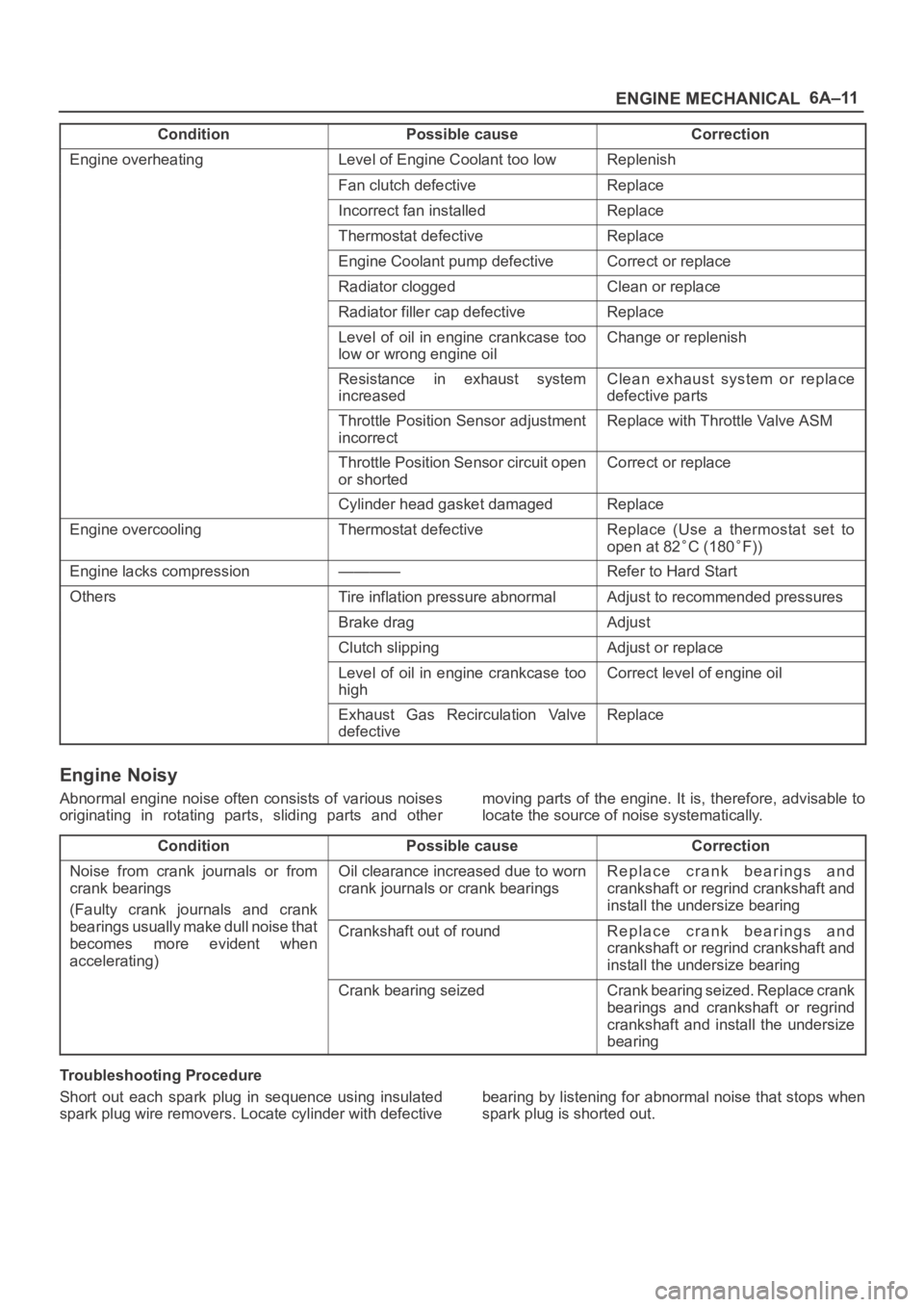
6A–11
ENGINE MECHANICAL
Condition CorrectionPossible cause
Engine overheatingLevel of Engine Coolant too lowReplenish
Fan clutch defectiveReplace
Incorrect fan installedReplace
Thermostat defectiveReplace
Engine Coolant pump defectiveCorrect or replace
Radiator cloggedClean or replace
Radiator filler cap defectiveReplace
Level of oil in engine crankcase too
low or wrong engine oilChange or replenish
Resistance in exhaust system
increasedClean exhaust system or replace
defective parts
Throttle Position Sensor adjustment
incorrectReplace with Throttle Valve ASM
Throttle Position Sensor circuit open
or shortedCorrect or replace
Cylinder head gasket damagedReplace
Engine overcoolingThermostat defectiveReplace (Use a thermostat set to
open at 82
C (180F))
Engine lacks compression————Refer to Hard Start
OthersTire inflation pressure abnormalAdjust to recommended pressures
Brake dragAdjust
Clutch slippingAdjust or replace
Level of oil in engine crankcase too
highCorrect level of engine oil
Exhaust Gas Recirculation Valve
defectiveReplace
Engine Noisy
Abnormal engine noise often consists of various noises
originating in rotating parts, sliding parts and othermoving parts of the engine. It is, therefore, advisable to
locate the source of noise systematically.
Condition
Possible causeCorrection
Noise from crank journals or from
crank bearings
(Faulty crank journals and crankOil clearance increased due to worn
crank journals or crank bearingsReplace crank bearings and
crankshaft or regrind crankshaft and
install the undersize bearing
yj
bearings usually make dull noise that
becomes more evident when
accelerating)Crankshaft out of roundReplace crank bearings and
crankshaft or regrind crankshaft and
install the undersize bearing
Crank bearing seizedCrank bearing seized. Replace crank
bearings and crankshaft or regrind
crankshaft and install the undersize
bearing
Troubleshooting Procedure
Short out each spark plug in sequence using insulated
spark plug wire removers. Locate cylinder with defectivebearing by listening for abnormal noise that stops when
spark plug is shorted out.
Page 974 of 6000
6A–18
ENGINE MECHANICAL
Cylinder Head Cover LH
Removal
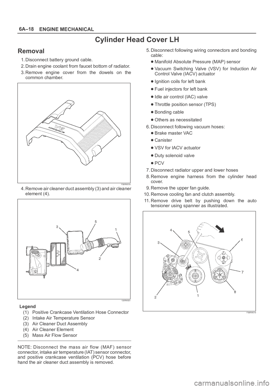
1. Disconnect battery ground cable.
2. Drain engine coolant from faucet bottom of radiator.
3. Remove engine cover from the dowels on the
common chamber.
F06RW018
4. Remove air cleaner duct assembly (3) and air cleaner
element (4).
130RW001
Legend
(1) Positive Crankcase Ventilation Hose Connector
(2) Intake Air Temperature Sensor
(3) Air Cleaner Duct Assembly
(4) Air Cleaner Element
(5) Mass Air Flow Sensor
NOTE: Disconnect the mass air flow (MAF) sensor
connector, intake air temperature (IAT) sensor connector,
and positive crankcase ventilation (PCV) hose before
hand the air cleaner duct assembly is removed.5. Disconnect following wiring connectors and bonding
cable:
Manifold Absolute Pressure (MAP) sensor
Vacuum Switching Valve (VSV) for Induction Air
Control Valve (IACV) actuator
Ignition coils for left bank
Fuel injectors for left bank
Idle air control (IAC) valve
Throttle position sensor (TPS)
Bonding cable
Others as necessitated
6. Disconnect following vacuum hoses:
Brake master VAC
Canister
VSV for IACV actuator
Duty solenoid valve
PCV
7. Disconnect radiator upper and lower hoses
8. Remove engine harness from the cylinder head
cover.
9. Remove the upper fan guide.
10. Remove cooling fan and clutch assembly.
11. Remove drive belt by pushing down the auto
tensioner using spanner as illustrated.
F06RW019
Page 975 of 6000
6A–19
ENGINE MECHANICAL
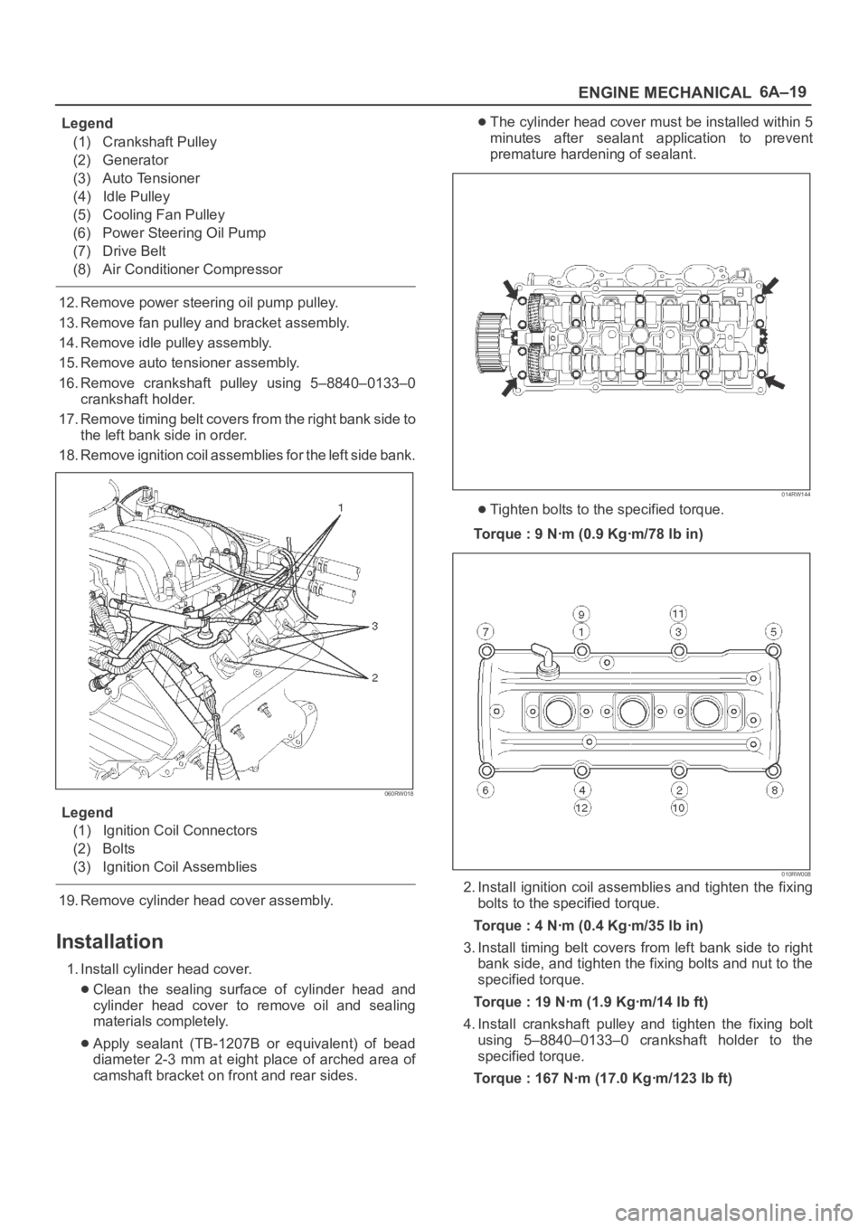
Legend
(1) Crankshaft Pulley
(2) Generator
(3) Auto Tensioner
(4) Idle Pulley
(5) Cooling Fan Pulley
(6) Power Steering Oil Pump
(7) Drive Belt
(8) Air Conditioner Compressor
12. Remove power steering oil pump pulley.
13. Remove fan pulley and bracket assembly.
14. Remove idle pulley assembly.
15. Remove auto tensioner assembly.
16. Remove crankshaft pulley using 5–8840–0133–0
crankshaft holder.
17. Remove timing belt covers from the right bank side to
the left bank side in order.
18. Remove ignition coil assemblies for the left side bank.
060RW018
Legend
(1) Ignition Coil Connectors
(2) Bolts
(3) Ignition Coil Assemblies
19. Remove cylinder head cover assembly.
Installation
1. Install cylinder head cover.
Clean the sealing surface of cylinder head and
cylinder head cover to remove oil and sealing
materials completely.
Apply sealant (TB-1207B or equivalent) of bead
diameter 2-3 mm at eight place of arched area of
camshaft bracket on front and rear sides.
The cylinder head cover must be installed within 5
minutes after sealant application to prevent
premature hardening of sealant.
014RW144
Tighten bolts to the specified torque.
Torque : 9 Nꞏm (0.9 Kgꞏm/78 lb in)
010RW008
2. Install ignition coil assemblies and tighten the fixing
bolts to the specified torque.
Torque : 4 Nꞏm (0.4 Kgꞏm/35 lb in)
3. Install timing belt covers from left bank side to right
bank side, and tighten the fixing bolts and nut to the
specified torque.
Torque : 19 Nꞏm (1.9 Kgꞏm/14 lb ft)
4. Install crankshaft pulley and tighten the fixing bolt
using 5–8840–0133–0 crankshaft holder to the
specified torque.
Torque : 167 Nꞏm (17.0 Kgꞏm/123 lb ft)
Page 976 of 6000
6A–20
ENGINE MECHANICAL
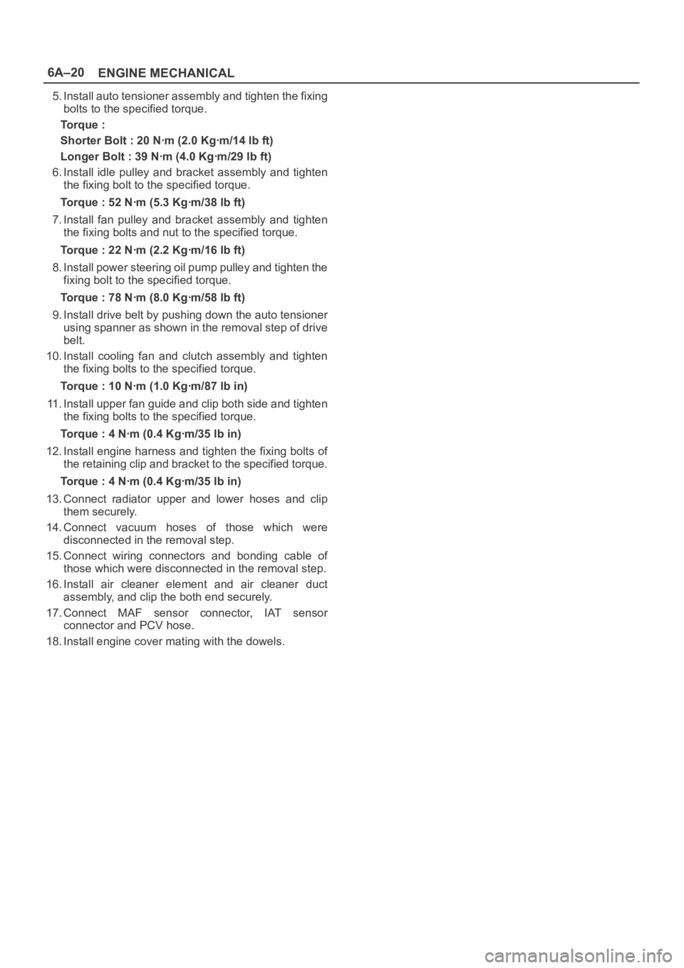
5. Install auto tensioner assembly and tighten the fixing
bolts to the specified torque.
Torque :
Shorter Bolt : 20 Nꞏm (2.0 Kgꞏm/14 lb ft)
Longer Bolt : 39 Nꞏm (4.0 Kgꞏm/29 lb ft)
6. Install idle pulley and bracket assembly and tighten
the fixing bolt to the specified torque.
Torque : 52 Nꞏm (5.3 Kgꞏm/38 lb ft)
7. Install fan pulley and bracket assembly and tighten
the fixing bolts and nut to the specified torque.
Torque : 22 Nꞏm (2.2 Kgꞏm/16 lb ft)
8. Install power steering oil pump pulley and tighten the
fixing bolt to the specified torque.
Torque : 78 Nꞏm (8.0 Kgꞏm/58 lb ft)
9. Install drive belt by pushing down the auto tensioner
using spanner as shown in the removal step of drive
belt.
10. Install cooling fan and clutch assembly and tighten
the fixing bolts to the specified torque.
Torque : 10 Nꞏm (1.0 Kgꞏm/87 lb in)
11. Install upper fan guide and clip both side and tighten
the fixing bolts to the specified torque.
Torque : 4 Nꞏm (0.4 Kgꞏm/35 lb in)
12. Install engine harness and tighten the fixing bolts of
the retaining clip and bracket to the specified torque.
Torque : 4 Nꞏm (0.4 Kgꞏm/35 lb in)
13. Connect radiator upper and lower hoses and clip
them securely.
14. Connect vacuum hoses of those which were
disconnected in the removal step.
15. Connect wiring connectors and bonding cable of
those which were disconnected in the removal step.
16. Install air cleaner element and air cleaner duct
assembly, and clip the both end securely.
17. Connect MAF sensor connector, IAT sensor
connector and PCV hose.
18. Install engine cover mating with the dowels.
Page 977 of 6000
6A–21
ENGINE MECHANICAL
Cylinder Head Cover RH
Removal
1. Disconnect battery ground cable.
2. Remove battery from the vehicle.
3. Drain engine coolant from faucet bottom of radiator.
4. Remove engine cover from the dowels on the
common chamber.
F06RW018
5. Remove air cleaner duct assembly (3) and air cleaner
element (4).
130RW001
Legend
(1) Positive Crankcase Ventilation Hose Connector
(2) Intake Air Temperature Sensor
(3) Air Cleaner Duct Assembly
(4) Air Cleaner Element
(5) Mass Air Flow Sensor
NOTE: Disconnect the mass air flow (MAF) sensor
connector, intake air temperature (IAT) sensor connector,
and positive crankcase ventilation (PCV) hose before
hand the air cleaner duct assembly is removed.
6. Disconnect following wiring connectors and bonding
cable:
Exhaust Gas Recirculation (EGR) valve
Fuel injectors for right bank
Ignition coils for right bank
Bonding cable
Othres as necessitated
7. Disconnect radiator upper and lower hoses.
8. Remove engine harness from the cylinder head
cover.
9. Remove the upper fan guide.
10. Remove cooling fan and clutch assembly.
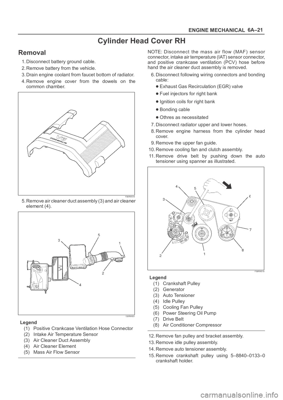
11. Remove drive belt by pushing down the auto
tensioner using spanner as illustrated.
F06RW019
Legend
(1) Crankshaft Pulley
(2) Generator
(3) Auto Tensioner
(4) Idle Pulley
(5) Cooling Fan Pulley
(6) Power Steering Oil Pump
(7) Drive Belt
(8) Air Conditioner Compressor
12. Remove fan pulley and bracket assembly.
13. Remove idle pulley assembly.
14. Remove auto tensioner assembly.
15. Remove crankshaft pulley using 5–8840–0133–0
crankshaft holder.