OPEL GT 2012 Owners Manual
Manufacturer: OPEL, Model Year: 2012, Model line: GT, Model: OPEL GT 2012Pages: 190, PDF Size: 2.46 MB
Page 131 of 190
13 1Self-help, vehicle care
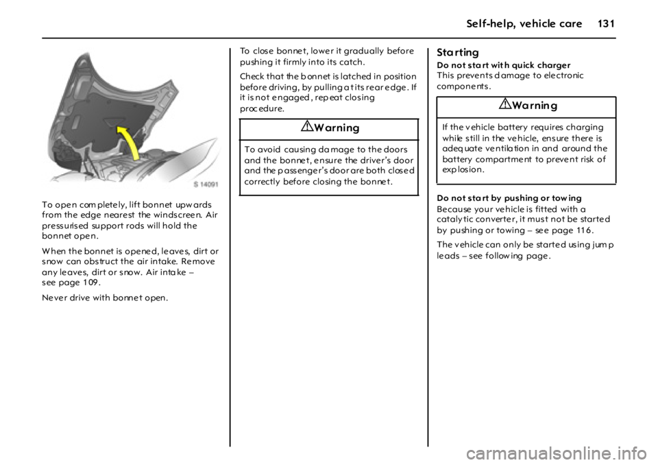
To ope n com plete ly, lift bonnet upw ards
from the edge neare st the windscree n. Air
pre ss uris ed support rods will hold the
bonnet open.
When the bonnet is opened, leaves, dirt or
snow can obstruct the air intake. Remove
any le ave s, dirt or s now. Air inta ke –
s ee page 1 09 .
Ne ve r drive with bonne t open.To clos e bonne t, lowe r it gradually before
pushing it firmly into its catch.
Check that the b onnet is latched in position
before driving, by pulling a t its re ar e dge . If
it is not e ngaged , rep eat clos ing
p r oc edu r e.
Sta rting
D o not s ta rt wit h quick charge r
This preve nts d amage to ele ctronic
compone nts .
D o not s ta rt by pus hing or tow ing
Be cause your ve hicle is fitted with a
cataly tic converte r, it must not be starte d
by pushing or towing – se e page 11 6 .
T h e v eh i cl e ca n o n l y be st a r t e d us i n g j um p
le ads – s ee follow ing page .
9 Warning
To avoid causing da mage to the doors
and the bonnet, ensure the driver’s door
and the p ass enge r’s door are both clos e d
correctly before closing the bonne t.
9 Wa r nin g
If t h e v eh i cl e ba t t er y r equ i r es ch a r g i n g
while s till in the ve hicle, ens ure there is
adeq uate ventila tion in and around the
battery compartme nt to preve nt risk of
exp l os i o n .
Page 132 of 190
132 Self-help, vehicle care
Sta rting the en gine with
jump leads
3
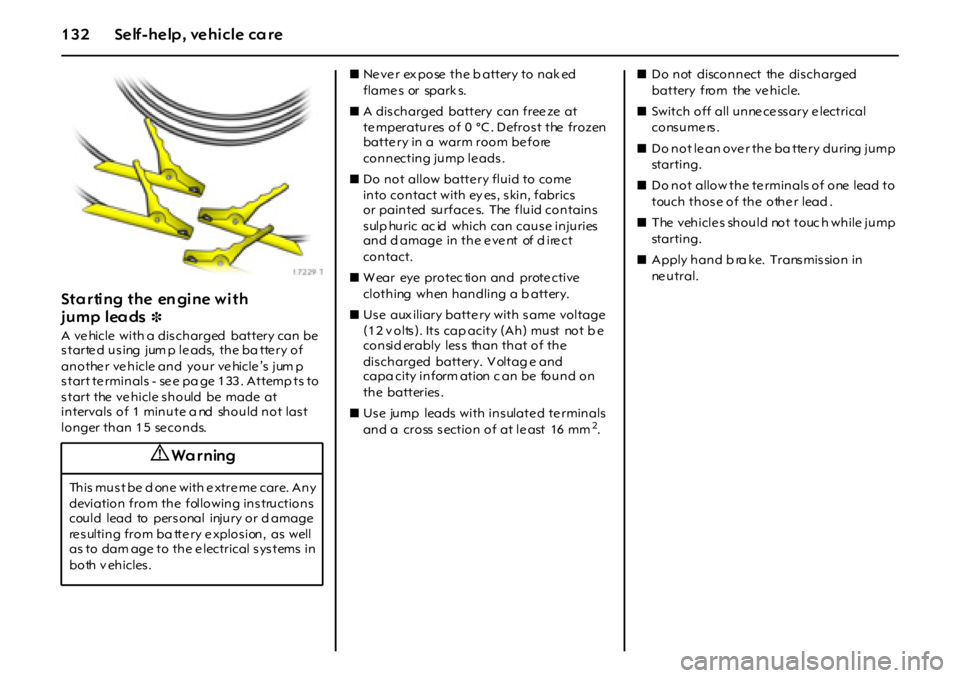
A ve hicle with a dis charged battery can be
s tarte d us ing jum p le ads, the ba tte ry of
anothe r ve hicle and your ve hicle ’s jum p
start te rminals - se e pa ge 133. Attemp ts to
start the vehicle should be made at
intervals of 1 minute a nd should not last
longer than 15 seconds.zNe ve r ex pose the b attery to nak ed
flame s or spark s.
zA dis charged battery can free ze at
te mperatures of 0 °C . Defrost the frozen
batte ry in a warm room be fore
connecting jump le ads .
zDo not allow batte ry fluid to come
into contact with ey es, skin, fabrics
or painted surfaces. The fluid contains
s ulp huric ac id which can caus e injuries
and d amage in the e ve nt of d ire ct
contact.
zW ear eye protec tion and prote ctive
clothing when handling a b attery.
zUs e aux iliary batte ry with s ame voltage
(12 volts). Its cap acity (Ah) must not b e
consid erably les s than that of the
dis charged battery. V oltag e and
capa city inform ation c an be found on
the batteries.
zUs e jump leads with ins ulate d te rminals
and a cross s ection of at le ast 16 mm
2. zDo not disconnect the discharged
battery from the ve hicle.
zSwitch off all unne ce ss ary e lectrical
cons ume rs .
zDo not le an ove r the ba tte ry during jump
st a r t i n g .
zDo not allow the te rminals of one lead to
touch those of the othe r lead .
zT he v eh i c l e s sh o u l d no t t o uc h w h i l e j u m p
st a r t i n g .
zApply hand b ra ke. Trans mis sion in
ne u t r a l .
9 Wa r ning
T h i s m u s t b e d o n e w i t h e x t r e m e c a r e . A n y
deviation from the following ins tructions
could lead to pers onal injury or d amage
re s ulting from ba tte ry e xplos ion, as well
as to dam age to the e lectrical systems in
both v ehicles .
Page 133 of 190

13 3Self-help, vehicle care
Jum p start te rminals
In the eve nt of a discharged battery , the
jump start term inals locate d in the e ngine
compartme nt enable the vehicle to be
starte d without the ne ed to access the
batte ry.
The p ositive jum p start terminal is
ide ntified by a “+” sign on the re d
insulating cov er, located nex t to the e ngine
compartme nt fuse box.
O pen the re d insulating cov er to acce ss the
positiv e “+” te rmina l c onne ctor. E nsure the
red insulating cove r is latche d ba ck into
pos ition whe n not in us e.The nega tiv e jump start te rminal is
identified by a “GND (-)” s ign on a ground
bracke t, located below the e ngine be auty
cover.C onne ct the le ads in the orde r shown in the
illustration:
1 . Co n n ect o n e en d o f t h e f ir s t j u m p l e a d
to the positive te rminal 1 of the ba tte ry
providing the jump start (ide ntifie d by
"+" sign o n batte r y cas e o r ter min al) .
2 . Co n n ect t h e o t he r en d of th i s l ea d t o
the positiv e jump start te rminal 2 of the
vehicle with the d ischarge d batte ry
("+" sign).
3. Connect the first e nd of the other jump
lead to the neg ativ e te rminal 3 of the
battery providing the jump start
("–" sign).
4. Connect the other end of the second
jum p lea d 4 to the ne gative jum p sta rt
terminal ground brack et, id entifie d by
“GND (-)”.
Page 134 of 190
134 Self-help, vehicle care
zDo not c onnec t leads to negative
te rminal of discharged battery!
zRoute the le ads so that the y ca nnot
catch on rotating p arts in the engine
com partment.
zStart the e ngine of the ve hicle p rov id ing
th e j u m p s t a r t .
zAfte r 5 minute s, sta rt the other e ngine .
Start attem pts should be made for no
longe r than 15 s econds at an interva l of
1 m i nu t e .
zAfte r the start, allow b oth engines to idle
for 3 minutes with the leads connected.
zIn ord er to av oid ex ces s voltage in the
el ec tr i ca l sy st e m , be f o r e r e m o vi n g a
le ad, switch on an e lectrical cons umer
(e .g. lamps , h ea te d re ar win do w) in th e
vehicle rece iving the jump start.
zReverse above sequence exactly when
re m o v i n g l e a d s .
Towing
Tow ing the vehicl e
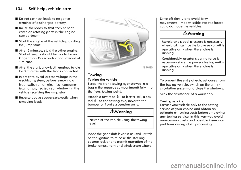
Screw the front towing ey e (stowed in a
bag in the lugga ge compartme nt) fully into
the front towing point.
Attac h a tow rope 3 - or b etter still, a tow
ro d 3 - to the towing ey e, neve r to the
bumper or front suspension units.
Plac e the gear s hift le ve r in ne utra l. Switch
on the ignition to re lease the stee ring
colum n lock and to p ermit operation of the
brake lamps , horn and winds cree n wipers . Drive off slowly and avoid jerky
mov eme nts . Impe rm iss ible trac tiv e force s
could da mage the ve hicles .
To prevent the entry of exha ust gases from
the tow ing vehicle , switch on the air re -
circulation sy stem and close the windows.
S ee k the a ss istance of a works hop.
Towi ng serv ice
E ntrust your ve hicle only to the towing
service of your choice and obtain an
e stimate on towing costs be fore e mploying
any tow ing se rvice. In this way y ou avoid
unnecessary c osts and possible insurance
proble ms during claim proce ss ing.
9 Warning
Ne ve r lift the ve hicle using the towing
eye!
9 Wa r nin g
More brake pedal pressure is necessary
w h en b ra ki n g s i n ce t he br a ke s er vo un i t i s
operative only when the engine is
running.
Conside rably greate r ste ering force is
necessary since the power steering unit is
operative only when the engine is
running.
Page 135 of 190
13 5Self-help, vehicle care
First-aid kit+3,
warning triangle¨3
Your first-aid kit and w arning triangle can
be accomm od ated in the luggage
compartme nt.
Vehicle tools
T h e f r o n t t o w i ng ey e s h o ul d be k ep t i n t h e
bag provided when not in use and s towed
in the lugga ge com partment.
Puncture
I n o r d er t o m i ni m i s e v eh i c l e w e i g ht , y o u r
vehicle is not fitte d with a jack or a spare
whee l.
It is recomm ended that whee l changing
and jacking of the vehicle are only carried
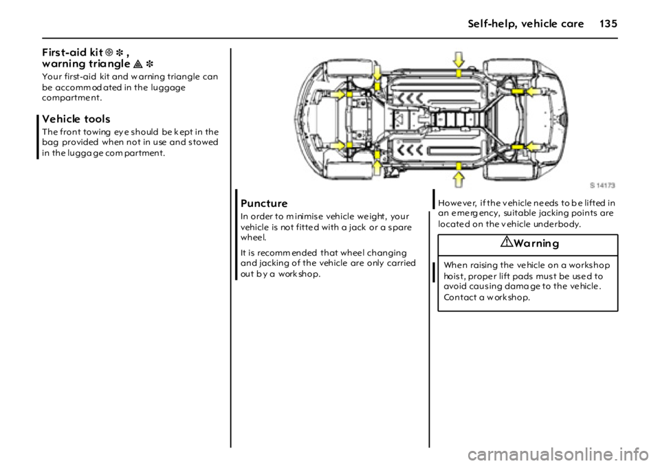
ou t b y a w or k sh o p .H o w e ve r, i f t h e v eh i cl e n e eds t o b e l i f t ed i n
an e me rg ency, suitable jacking points are
locate d on the v ehicle unde rbody.
9 Wa r nin g
When raising the vehicle on a workshop
hois t, prope r lift pads mus t be us e d to
avoid caus ing dama ge to the ve hicle .
Contact a w ork shop.
Page 136 of 190
136 Self-help, vehicle care
Tyre rep air k it
Minor damag e to the tyre tread, e.g . from
foreign bodie s, can be tem porarily
rep aire d using the ty re re pair kit.
Do not rem ov e foreign bodies from the
tyre s. Damage d are as bigger than 4 m m
and da mage at the ty re rim cannot be
rep aire d using the ty re re pair kit.
The tyre re pair k it can be use d to seal small
puncture s with a liquid seala nt. Use of the
sealant doe s not c onstitute a pe rmane nt
rep air but is des igned as an eme rgency
measure, to allow the vehicle to be driven
while awaiting tyre replace me nt.
The ty re re pair kit ca n also be used to
infla te the tyres to the c orre ct ty re pressure
(se e page 18 0 ) without us ing the s ea lant.For important information – s ee page 1 40 .
If you have a flat ty re:
zPark on a leve l, firm a nd non-s lippery
surface.
zSw itch on haz ard warning lamps , a pply
hand brak e, engage rev ers e ge ar and
switch off engine.
zC orre ctly s et up the warning triangle3.
W arning tria ngle – se e page 13 5 .
Nev er use the liquid sealant on more than
one tyre at a tim e.
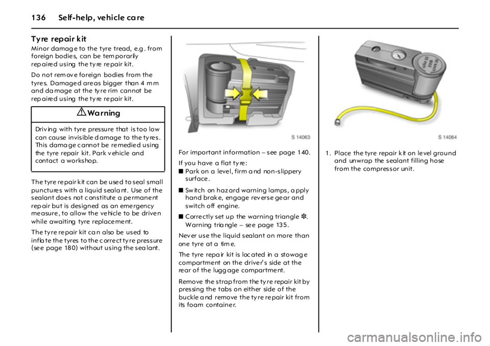
The tyre repa ir kit is loc ated in a stowag e
compartme nt on the drive r’ s side at the
re ar of the lugg age compartme nt.
Remove the strap from the ty re repair kit by
pressing the tabs on either side of the
buckle a nd remove the ty re re pair kit from
its foam containe r.
9 Wa r ning
Driv ing with tyre pressure that is too low
can cause invisible d amage to the ty re s.
This dama ge c annot be re medie d us ing
the tyre repair kit. Park v ehicle and
contact a works hop.
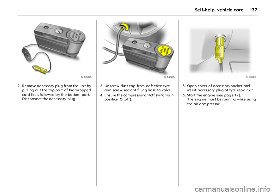
1 . Place the tyre repair k it on le vel ground
and unwrap the s ealant filling hose
from the compressor unit.
Page 137 of 190
13 7Self-help, vehicle care
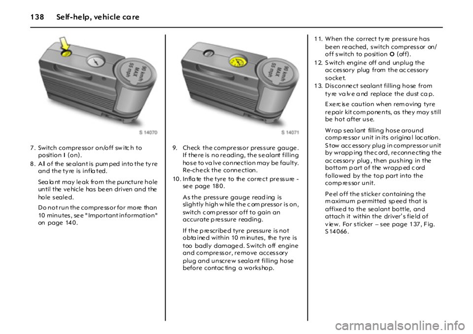
2 . Re move ac ces sory plug from the unit by
pulling out the top pa rt of the wrappe d
cord first, follow ed b y the bottom part.
Dis conne ct the ac ces sory plug.3. Unscrew dust cap from defective tyre
and scre w s ealant filling hose to valve .
4. E nsure the compre ssor on/off sw itc h is in
pos ition O (off).5 . Ope n cove r of acce ss ory s ocket and
insert accessory plug of tyre rep air kit.
6 . St a r t t h e en g i n e (s ee p a g e 1 7 ).
The eng ine must be running while using
the air c om pressor.
Page 138 of 190
138 Self-help, vehicle care
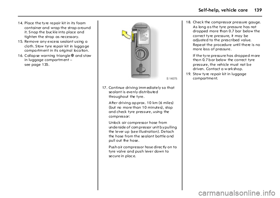
7 . Switch compre ss or on/off sw itc h to
position I(on).
8 . All of the se alant is pum ped into the ty re
and the ty re is infla ted.
Sea la nt may le ak from the puncture hole
un t i l t he v e hi c l e ha s b e en d r i v en a n d t he
ho l e s ea l e d .
Do not run the compressor for more than
10 minutes, see " Important information"
on page 14 0 .9. Check the compre ss or pres s ure gauge .
If the re is no re ading, the s e alant filling
hose to va lve conne ction may be faulty.
Re-che ck the conne ction.
10. Infla te the tyre to the corre ct pre ssure -
se e page 18 0 .
As the pres s ure gauge read ing is
slightly high w hile the c om pres sor is on,
switch c om pres sor off to gain an
accurate p re ssure reading.
If the p re scribe d tyre pressure is not
obta ine d within 10 m inutes , the tyre is
too badly damage d. S witch off engine
and compre ssor, re move accessory
plug and unscre w s eala nt filling hose
before contac ting a works hop.
11. When the correct ty re pressure has
be en re ached, switch compressor on/
off switch to position O(off).
1 2. S witch engine off and unplug the
ac ces sory plug from the ac ces sory
socket.
1 3. Dis conne ct s ealant filling hose from
ty re va lv e a nd replace the dust ca p.
E x e rc is e c a u t i o n w h en r em o v i ng t y r e
re pair kit com pone nts, as the y may s till
be hot after use.
W rap s ea lant filling hos e around
comp re s sor unit in its origina l loc ation.
S tow acc essory plug in compressor unit
by wrapp ing the c ord, re conne cting the
ac ces sory plug , then pus hing in the
bottom p art of the wrapp ed c ord
followed by the top part into the
comp ressor unit.
P e el o f f t h e s t i cke r co n t a i ni n g t h e
m aximum p ermitted sp ee d that is
affixe d to the se alant bottle, and
attach it within the driver’ s fie ld of
v ie w. For s ticker – s ee page 1 37 , F ig.
S14066.
Page 139 of 190
13 9Self-help, vehicle care
14. Place the ty re re pair kit in its foam
container and wrap the strap a round
it. S nap the buc kle into place and
tighten the strap as ne ce ss ary.
1 5. Re move any e xce ss s ealant us ing a
cloth. S tow tyre re pair kit in lugga ge
compa rtm ent in its orig inal loca tion.
1 6. C ollap se warning triangle3 and s tow
in luggage compartm ent –
s ee page 1 35 .
17 . Continue driving imm ediate ly s o that
se alant is eve nly dis tribute d
throughout the tyre .
Afte r driving ap prox . 1 0 km (6 mile s)
( b ut no m o r e t h a n 1 0 m i n ut e s) , st o p
and check tyre pres s ure , us ing the
compressor:
Unlock air compre ss or hose from
unde rside of com pres sor unit b y pulling
the le ver up (s e e illustration). De tach
the hose from the se alant bottle a nd
pull out the hose .
Push a ir compre ssor hose direc tly on to
tyre valve and pus h leve r down to
se cure in plac e.1 8. Chec k the compres s or pre ss ure gauge.
As long a s the tyre pressure has not
dropped more than 0 .7 bar below the
correct ty re pre ssure, it may be
a dj u st e d t o t h e p r es cr i bed va l u e.
Repe at the procedure until the re is no
more loss of pressure .
If the ty re pre ssure has droppe d m ore
tha n 0. 7 b ar below the correct tyre
pressure , the vehicle must not b e
driven . Co n tact a w ork sh o p.
1 9. Stow ty re re pair kit in luggage
compartme nt.
Page 140 of 190

140 Self-help, vehicle care
Im po rtan t The driving characte ristics of the re paired
tyre is se ve re ly affe cted , there fore hav e this
tyre rep laced without d elay by a w ork shop.
If unusual noise is heard or the compressor
become s hot, turn c om pressor off for at
least 30 m inute s.
The built-in safety va lve opens at a
pressure of 7 bar.
Protect compressor from moisture and
ra i n.Pay attention to storage inform ation and
be st before date on s ea lant bottle . I ts
s ealing c apability is not guarantee d after
this time.
The se alant bottle ca n only be use d once.
Re place use d s ealant bottle .
The compres s or and se alant can be us ed
from app rox . -3 0 °C.
Dispose of used tyre rep air kits in
acc orda nce with the applicable laws .
C onsumers must not be connected to the
acc es sory socke t at the sam e time whe n
the tyre re pair kit is be ing use d.
9 Wa r ning
Do no t d ri v e f a s t er t h a n 9 0 km / h
(5 5 m p h ) .
Have the re paired tyre re place d as s oon
as p ossible.
Do not d riv e with m ore than one
te mporarily re paired tyre.
Stee ring and handling may be affe cted .
Ta ke b ends slowly.
Only stow the ty re re pair kit in the
lugga ge c om partment.