ECO mode OPEL GT-R 1973 Service Manual
[x] Cancel search | Manufacturer: OPEL, Model Year: 1973, Model line: GT-R, Model: OPEL GT-R 1973Pages: 625, PDF Size: 17.22 MB
Page 10 of 625
GENERAL INt=ORMATION OA-1
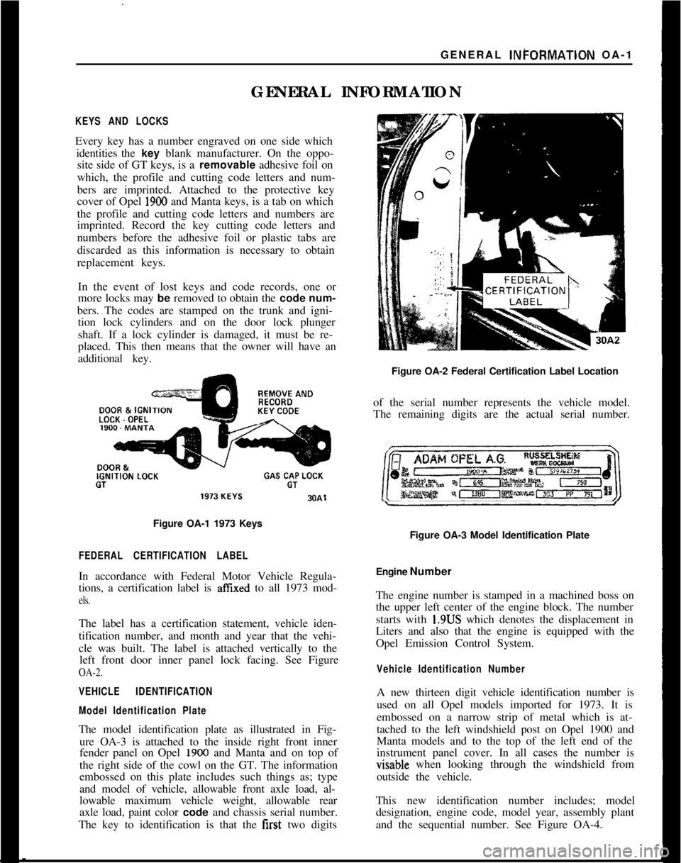
GENERAL INFORMATIONKEYS AND LOCKSEvery key has a number engraved on one side which
identities the key blank manufacturer. On the oppo-
site side of GT keys, is a removable adhesive foil on
which, the profile and cutting code letters and num-
bers are imprinted. Attached to the protective key
cover of Opel
1900 and Manta keys, is a tab on which
the profile and cutting code letters and numbers are
imprinted. Record the key cutting code letters and
numbers before the adhesive foil or plastic tabs are
discarded as this information is necessary to obtain
replacement keys.
In the event of lost keys and code records, one or
more locks may be removed to obtain the code num-
bers. The codes are stamped on the trunk and igni-
tion lock cylinders and on the door lock plunger
shaft. If a lock cylinder is damaged, it must be re-
placed. This then means that the owner will have an
additional key.REMOVE ANDDOOR &
IGNIKEY CODELOCK. OPELIGNITION
LOCKGAS CAP LOCKGTGT
Figure OA-1 1973 Keys
FEDERAL CERTIFICATION LABELIn accordance with Federal Motor Vehicle Regula-
tions, a certification label is
affIxed to all 1973 mod-
els.The label has a certification statement, vehicle iden-
tification number, and month and year that the vehi-
cle was built. The label is attached vertically to the
left front door inner panel lock facing. See Figure
OA-2.
VEHICLE IDENTIFICATION
Model Identification PlateThe model identification plate as illustrated in Fig-
ure OA-3 is attached to the inside right front inner
fender panel on Opel
1900 and Manta and on top of
the right side of the cowl on the GT. The information
embossed on this plate includes such things as; type
and model of vehicle, allowable front axle load, al-
lowable maximum vehicle weight, allowable rear
axle load, paint color code and chassis serial number.
The key to identification is that the first two digitsFigure OA-2 Federal Certification Label Location
of the serial number represents the vehicle model.
The remaining digits are the actual serial number.
Figure OA-3 Model Identification Plate
Engine Number
The engine number is stamped in a machined boss on
the upper left center of the engine block. The number
starts with 1.9US which denotes the displacement in
Liters and also that the engine is equipped with the
Opel Emission Control System.
Vehicle Identification NumberA new thirteen digit vehicle identification number is
used on all Opel models imported for 1973. It is
embossed on a narrow strip of metal which is at-
tached to the left windshield post on Opel 1900 and
Manta models and to the top of the left end of the
instrument panel cover. In all cases the number isvisable when looking through the windshield from
outside the vehicle.
This new identification number includes; model
designation, engine code, model year, assembly plant
and the sequential number. See Figure OA-4.
Page 16 of 625
LUBRICATION AND MAINTENANCE OC-7SERVICESLUBE AND GENERAL MAINTENANCE
Vehicle operation under conditions such as heavy
dust, continuous short trips, use of other than un-
leaded or low lead fuels or pulling trailers, is not
considered normal use and therefore more frequent
maintenance will be required. Such additional
maintenance requirements are included where appli-
cable.
Engine OilChange each 4 months or
3,COO miles, whichever
occurs first, or each 2 months or
3,ooO miles when
the vehicle is operated under the following condi-
tions: (a) driving in dusty conditions, (b) trailer pull-
ing, (c) extensive idling or (d) short-trip operation at
freezing temperatures (with engine not thoroughly
warmed-up).Engine oils have a definite effect on ease of starting,
oil economy, combustion chamber deposits and en-
gine wear. It is recommended that a” oil which,
according to the label on the can is; (1) intended for
service SE and (2) passes car makers’ tests be used.
Oils confotming to these types contain detergent ad-
ditives. -
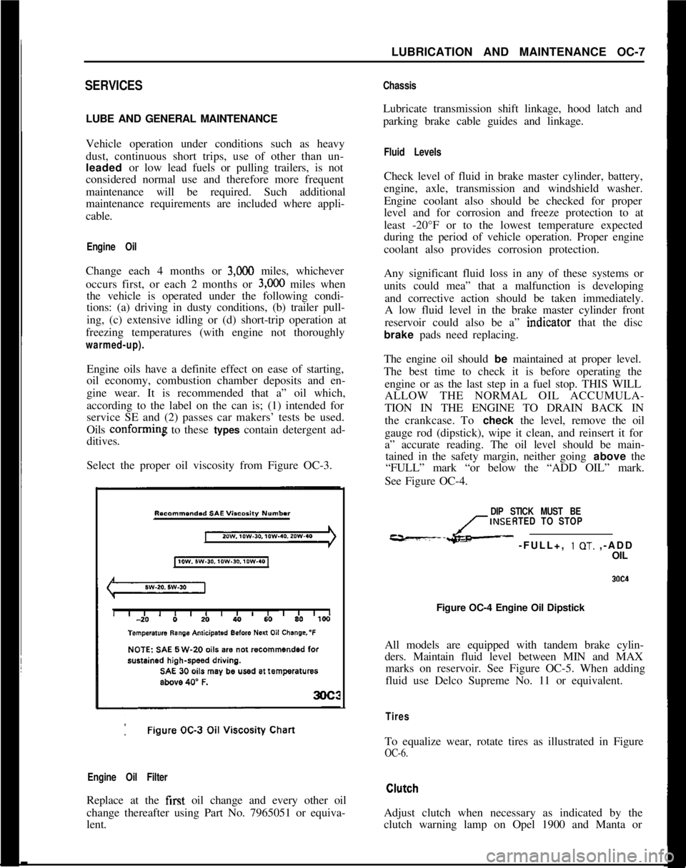
Select the proper oil viscosity from Figure OC-3.
Engine Oil FilterReplace at the first oil change and every other oil
change thereafter using Part No. 7965051 or equiva-
lent.
ChassisLubricate transmission shift linkage, hood latch and
parking brake cable guides and linkage.
Fluid LevelsCheck level of fluid in brake master cylinder, battery,
engine, axle, transmission and windshield washer.
Engine coolant also should be checked for proper
level and for corrosion and freeze protection to at
least -20°F or to the lowest temperature expected
during the period of vehicle operation. Proper engine
coolant also provides corrosion protection.
Any significant fluid loss in any of these systems or
units could mea” that a malfunction is developing
and corrective action should be taken immediately.
A low fluid level in the brake master cylinder front
reservoir could also be a” indtcator that the disc
brake pads need replacing.
The engine oil should be maintained at proper level.
The best time to check it is before operating the
engine or as the last step in a fuel stop. THIS WILL
ALLOW THE NORMAL OIL ACCUMULA-
TION IN THE ENGINE TO DRAIN BACK IN
the crankcase. To check the level, remove the oil
gauge rod (dipstick), wipe it clean, and reinsert it for
a” accurate reading. The oil level should be main-
tained in the safety margin, neither going above the
“FULL” mark “or below the “ADD OIL” mark.
See Figure OC-4.
DIP STICK MUST BE
INSERTED TO STOP
---L- -FULL+, 1 OT. ,-ADD
OIL
Figure OC-4 Engine Oil Dipstick
All models are equipped with tandem brake cylin-
ders. Maintain fluid level between MIN and MAX
marks on reservoir. See Figure OC-5. When adding
fluid use Delco Supreme No. 11 or equivalent.
TiresTo equalize wear, rotate tires as illustrated in Figure
OC-6.Adjust clutch when necessary as indicated by the
clutch warning lamp on Opel 1900 and Manta or
Page 19 of 625
CC-10 1973 OPEL SERVICE MANUAL
wiper blades. Check amount and direction of fluid
sprayed by washers during use.,
E. Defrosters - Check performance by moving con-
trols to “DEF” and noting
am$nmt of air directed
against the windshield.
I
F. Wheel Alignment and
Balabce - In addition to
abnormal tire wear, the need fbr wheel alignment
service may be indicated by a pull to the right or
!eftwhen driving on a straight and level road. The need
for wheel balancing is usually
iddicated by a vibra-
tion of the steering wheel or
se;+ tihile driving at
normal highway speeds.I
IG. Brakes
- Be alert to illumiriation of the brake
warning light or changes in braking action,
SUCK as
repeated pulling to one side, unusual sounds when
braking or increased brake pedal travel. Any of thesecould indicate the need for
brakk system inspection
and/or service.
H. Parking Brake and Transmission “PARK”
Mechanism
- Check parking brake holding ability by
parking on a fairly steep hill and restraining the vehi-
cle with the parking brake only.
eon cars with auto-
matic transmissions, check the holding ability of the
“PARK” mechanism by releasing all brakes after
the transmission selector lever hak been placed in the“P” position.
I. Glass
- Check for broken, scrritched, dirty or da-
maged glass on vehicle that
coulld obscure vision’or
become an injury hazard.
J. Lights and Buzzers
- Check all instrument panel
illuminating and warning lights,’ seat belt reminder
light and buzzer, ignition key
b&er, interior lights,
license plate lights, side marker! lights, headlamps,
parking lamps, tail lamps, brake lights, turn signals,
backup lamps, and hazard warding flashers. Have
someone observe operation of
&ach exterior light
while you activate the controls: The operation of
instrument panel warning lights is covered in the
“Starting and Operating“ section of your
Own&%
Manual.K. Transmission Shift Indicator
‘- Check to be sure
automatic transmission shift
indiCator accurately i”-
dicates the shift position selected.
I
CAUTION: Before making thk check below,I
be sure to have a clear dist&e ahead and:
behind the car, set the parking brake and
firmly apply the foot brake.
Do not depress
accelerator pedal. Be prepared to
turn off ’
ignition switch
immediat+y if engine
should start.L. Starter Safety Switch (Automatic Transmissibn
Cars)
- Check starter safety switch by placing the
transmission in each of the driving gears while
at-tempting to start the engine. The starter should oper-ate only in the Park (“P”) or Neutral (“N”)
positions.
M. Horn
- Blow the horn occasionally to be sure thatit works. (Ignition switch must be in the “ON” posi-
tion.)
N. Seat Back Latches
- Check to see that seat back
latches are holding by pulling forward on the top of
each folding seat back.
0. Rearview Mirrors and Sun Visors
- Check that
friction joints are properly adjusted so mirrors and
sun visors stay in the selected position.
P. Door Latches
- Check for positive closing, latch-
ing and locking.
Q. Hood Latches - Check to make sure hood closesfirmly by pressing on the hood at the latching point
after each closing. Check also for broken, damaged
or missing parts which might prevent secure latch-
ing.R. Fluid Leaks
- Check for fuel, water, oil or other
fluid leaks by observing the ground beneath the vehi-cle after it has been parked for a while. If gasoline
fumes or fluid are noticed at any time, the cause
should be determined and corrected without delay
because of the possibility of fire.
S. Exhaust System
- Be alert to any change in the
sound of the exhaust system or a smell of fumes
which may indicate a leak.
Head Restraints
- Check that no head restraint
components are missing, damaged or loose. (Does
not apply to GT Models).
Disc BrakesCheck brake pads and condition of rotors while
wheels are removed during tire rotation. (Note belowregarding more frequent checks also applies to disc
brakes.)
Parking and Drum BrakesCheck drum
brake linings and other internal brake
components at each wheel (drums, wheel cylinders,
etc.). Parking brake adjustment also should be
checked whenever drum brake linings are checked.
NOTE: More frequent checks should be
made if driving conditions a.nd habits result
in frequent brake application. When brakes
require relining, it is recommended thatyou use those genuine General Motors
parts specified for your car,and Delco fluid
as required.
Page 24 of 625
BATTERY AND CABLES - ALL MODELSlA- 3
lost as the result of charging and discharging, and it
must be replaced before the electrolyte level falls to
the tops:of the separators. If the water is not replacedand the plates become exposed, they may become
permanently sulphated, which would impair the
per-forma”& of the plates. Also, the plates cannot take
full
par! in the battery action unless they are com-
pletely covered by the electrolyte.
Importance of Keeping Battery Properly Charged
The battery has three major functions: (1) It provides
a source of energy for cranking the engine. (2) It actsas a stabilizer to the voltage in the electrical system.
(3) It
c+n for a limited time furnish energy when the
demand: of the electrical units in operation exceed
the output of the generator.
In
ordei for the battery to continue to function, it is
necessaiy that current withdrawal from the battery
be balanced by current input from the generator so
that the battery is maintained in a properly chargedconditidn. If the outgo exceeds the input, the battery
will be&me discharged so that it cannot.supply suffi-cient energy.
The state of charge of the battery as well as the
temperature of the electrolyte has an important bear-ing on its capacity for supplying energy. Battery effi-
ciency is greatly reduced by decreased electrolyte
temper&e as it has a decided numbing effect on its
electrodhemical action. Under high discharge such
as cranking, battery voltage drops to lower values incold temperatures than in warm temperatures.
In
extrkmely cold climates it is important to keepbatter& in a nearly full charged condition to avoid
the possibility of freezing, which will damage any
battery!
The following table shows the temperatures at whichfreezing will occur in electrolytes of
differennt densi-
ties, wifh specific gravity corrected to 80 degrees l?
Specific Gravity Freezing Point
1.220 -35 degrees F.
1.200
-35 degrees F.
1.160
d degrees F.
Care of Dry Batteries in StorageA “dry charge” battery contains fully charged posi-
tive
a$ negative plates but no electrolyte.
Dry charged batteries should be stored in a dry placeaway from excessive heat. A dry charged battery
should
p kept in its original carton until ready to beput into service. This type of battery will retain its
“charged” condition indefinitely if protected from
moisture. Dry batteries may be stacked in vertical
columns provided they are not stacked more than
four high.
Preparing Dry Charged Batteries For ServiceTo prepare “dry charge” batteries for service use
approved battery-grade acid electrolyte (1.265 sp. gr.
at 80 degrees F). Care should be exercised in its useto prevent bodily injury or damage to clothing or
other material resulting from actual contact with the
electrolyte.
Electrolyte should be added to dry charged batteriesin an area where water is readily available for flush-
ing in case the electrolyte comes into contact with the
body. Refer to instructions on side of electrolyte con-tainer for antidotes to use if electrolyte comes into
contact with the body.
It is strongly recommended that a person filling bat-
teries with electrolyte wear glasses (preferably safetyglasses) to prevent possible damage to the eyes
should any spattering of the electrolyte occur.
1, Remove dry charged battery from its original car-
ton.2. Remove the vent plugs.
3. Using a glass or acid-proof plastic funnel, till eachbattery cell with electrolyte. Do not use a metal
funnel for filling the battery. The cell is properlytilled when the electrolyte level rises to the split ring
at the bottom of the vent well. Do not overfill orundertill. Overfilling will cause acid corrosion in the
,battery area; undertilling will cause early battery fail-
UR.4. After tilling cells, wait five to ten minutes and add
additional electrolyte, if necessary, to bring the elec-
trolyte to the proper level.
5. Never finish tilling a dry charge battery with wa-
ter. If electrolyte is spilled, more electrolyte must be
obtained.
Test After Batteries
ere Prepared For ServiceThe Delco Dry Charge Battery may be put into ser-
vice immediately after activation. However, to insuregood battery performance, the following activation
tests are recommended:1. After adding electrolyte,, check the open circuit
voltage. Less than 10 volts mdicates a reverse cell oran open circuit and the battery should be replaced.
2. Check the specific gravity of all cells. If the specific
Page 26 of 625
BATTERY AND CABLES - ALL MODELSlA- 5
and terminal connections should not exceed 2/10
volt.
5. Connedt voltmeter positive lead to ground on en-
gine.
At&h prod to voltmeter negative lead and
apply prod to center of battery negative post. Volt-
age drop across the battery ground cable and termi-
nal conne$tions should not exceed 2/10 volt at
200amps.
6. A reading in excess of 2/10 volt when testing
either battery cable indicates excessive resistance in
cable or cpnnections. Clean and tighten cable or con-
nections. Clean and tighten cable terminals
(sub-para. c, below) and recheck for voltage drop. If volt-
age drop Still exceeds 2/10 volt, replace cable with a
genuine Buick-Opel cable to insure ample capacity.
Undercharge Failure of BatteryThe most frequent trouble experienced with storage
batteries is failure to maintain a state of charge suffi-
cient to crank the engine and also furnish current to
the ignitibn system, lights and accessories. Failure to
maintain a proper state of charge may be due to one
or more of the following conditions:
1.
Opertiting Conditions. When determining cause
of premature failure of a battery, consideration must
be given /to the conditions under which the car is
operated.,
In very low temperatures the capacity of a storage
battery
ii considerably reduced and the energy re-
quired f& cranking the. engine is considerably in-
creased. :
Frequent starting, particularly in cold weather,
ac-compani
place in the limited running time. This condition is
aggravated by night driving when lights are turned
on, or by operation of an air conditioner in heavy
traffic.
When thk car is operated under these conditions,adjusting,the voltage regulator to the high limit may
allow enough increase to keep the battery at a safe
state of charge. If the high limit setting does not
maintain a safe state of charge, an occasional booster
charge should be given to the battery.
2. Low charging Rate. In case of premature battery
failure, tbe charging rate of alternator should always
be checked and adjusted if below specifications.
3.
Zntemd Condition The internal condition of the
battery niay be such that it cannot hold a chargesatisfactoiily. Check electrolyte level and test the
battery using the 421 Battery Test.
Overcharge Failure of BatteryA common cause of battery failure is overcharging,
that is, continued input of excessive charging current
after the battery has reached a fully charged condi-
tion.
One evidence that battery is being overcharged is the
need for frequent addition of water to the battery in
order to maintain the electrolyte level above the tops
of the battery separators, since overcharging causes
rapid water loss. When this becomes evident, the
charging rate of alternator should be immediately
checked, as well as the voltage regulator, and ad-
justed to avoid internal damage to battery.
ADJUSTMENTS AND MINOR SERVICEPERIODIC BATTERY INSPECTION AND SERVICE
The battery requires very little attention, but peri-
odic inspection is essential to secure the maximum
efficiency and life. The following services are essen-
tial to maintain the battery at maximum efficiency.
WARNING: Never expose battery to open flame or
electric spark
- battery action generates hydrogen gas
which is flammable and explosive. Do not allow bat-
tery fluid to contact skin, eyes, fabrics or painted
surfaces
- fluidis a sulfuric acid solution which could
cause serious personal injury or property damage.
Wear eye protection when working with battery.
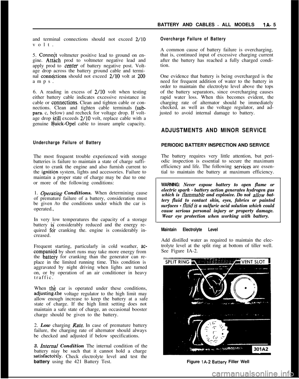
Maintain Electrolyte LevelAdd distilled water as required to maintain the elec-
trolyte level at the split ring at bottom of tiller well.
See Figure IA-2.
Figure lA-2
Battery Filler Well
Page 29 of 625
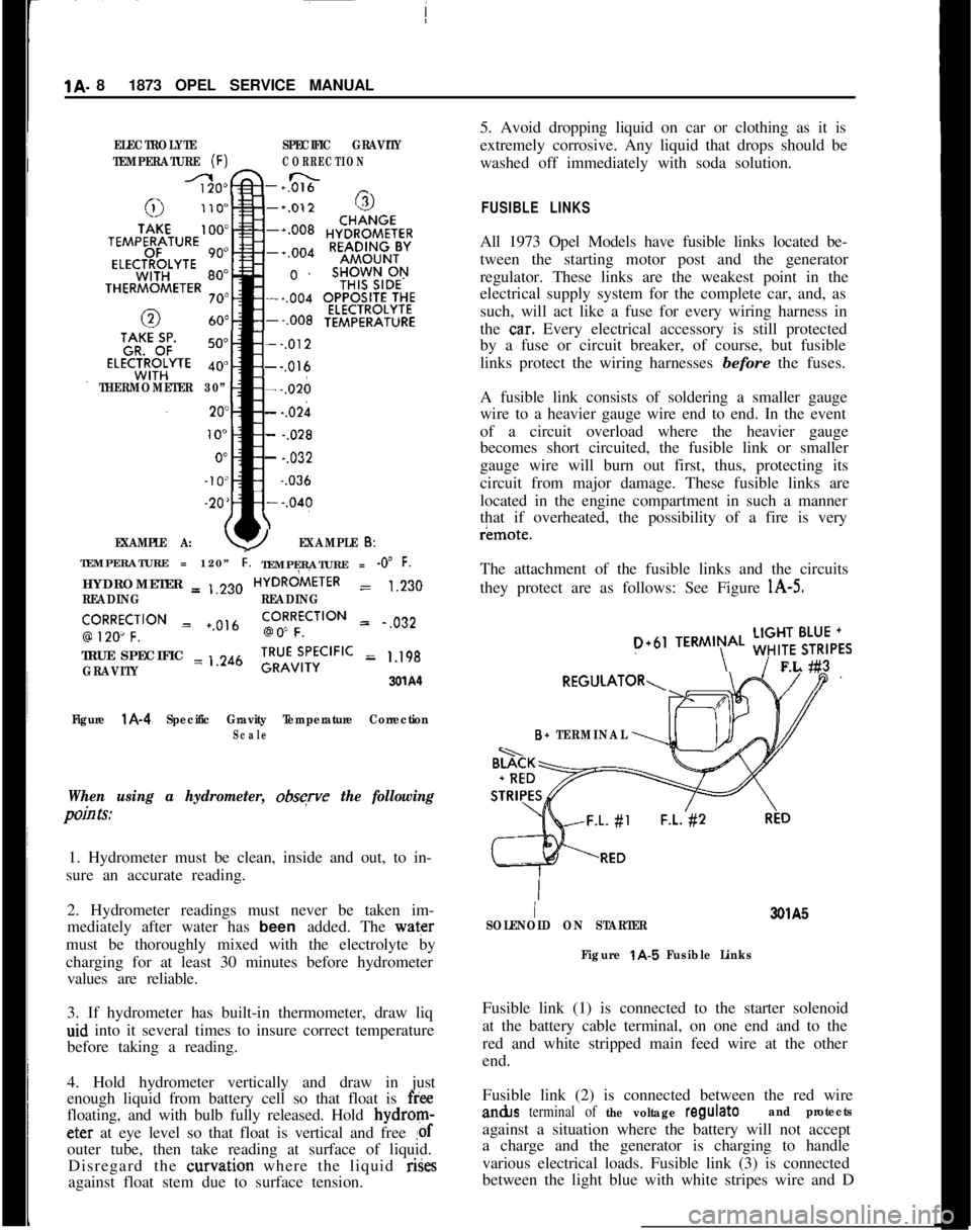
1A. 81873 OPEL SERVICE MANUALELECTROLYTESPECIFIC GRAVITY
TEMPERATURE
(F)CORRECTION
-+0&&n _
THERMOMETER 30”
EXAMPLE A:
--,012---,016---,026
- -.02h
- -.028
- -.032~
-.036
YEXAMPLE 6:TEMPERATURE = 120”
i.TEMPERATURE = -0” F.HYDROMETER = ,,230HYDRdiETER
= 1.230
READINGREADING
‘,9R2Ro~CF;‘“” = +.0,6go!RFfCilON = .,032
TRUE SPECIFIC = ,.246
GRAVITY;RU”v;,‘;CIFIC = 1.198
3xA‘l
Figure
l A-4 Specific Gravity Temperature CorrectionScale
When using a hydrometer, obsqve the following
pain Is:1. Hydrometer must be clean, inside and out, to in-
sure an accurate reading.
2. Hydrometer readings must never be taken im-
mediately after water has been added. The water
must be thoroughly mixed with the electrolyte by
charging for at least 30 minutes before hydrometer
values are reliable.
3. If hydrometer has built-in thermometer, draw liq
aid into it several times to insure correct temperature
before taking a reading.
4. Hold hydrometer vertically and draw in just
enough liquid from battery cell so that float is
freefloating, and with bulb fully released. Hold bydrom-eter at eye level so that float is vertical and free
!ofouter tube, then take reading at surface of liquid.
Disregard the curvation where the liquid rises
against float stem due to surface tension.5. Avoid dropping liquid on car or clothing as it is
extremely corrosive. Any liquid that drops should be
washed off immediately with soda solution.
FUSIBLE LINKSAll 1973 Opel Models have fusible links located be-
tween the starting motor post and the generator
regulator. These links are the weakest point in the
electrical supply system for the complete car, and, as
such, will act like a fuse for every wiring harness in
the
ca.r. Every electrical accessory is still protected
by a fuse or circuit breaker, of course, but fusible
links protect the wiring harnesses before the fuses.
A fusible link consists of soldering a smaller gauge
wire to a heavier gauge wire end to end. In the event
of a circuit overload where the heavier gauge
becomes short circuited, the fusible link or smaller
gauge wire will burn out first, thus, protecting its
circuit from major damage. These fusible links are
located in the engine compartment in such a manner
that if overheated, the possibility of a fire is veryr¬e.
The attachment of the fusible links and the circuits
they protect are as follows: See Figure
l A-5.
D+61TERMIN\AL ;;!$6,,FL #3
B+ TERMINAL
I3QlA5
SOLENOID ON STARTER
Figure
t A-5 Fusible LinksFusible link (1) is connected to the starter solenoid
at the battery cable terminal, on one end and to the
red and white stripped main feed wire at the other
end.
Fusible link (2) is connected between the red wirean&s
terminal of the voltage regulateand protectsagainst a situation where the battery will not accept
a charge and the generator is charging to handle
various electrical loads. Fusible link (3) is connected
between the light blue with white stripes wire and D
Page 67 of 625
1F. 46 1973 OPEL SERVICE MANUAL
’
/
Headlight High-Low Beam Control and Passing:
SignalI
When the headlights have been switched on, high
and low beam selection is made by raising the direc-
tional signal lever toward steering wheel. Each
ti&the lever is raised, beam position, will change.
When the headlights are not on, a flashing headlight
signal may be given by raising and lotiering the di-
rectional signal lever. With the headlights on and
inlow beam position, raising and lowering the direc-
tional signal lever will also cause the headlights to
flash.
Fog Light SwitchAll Rallye models are equipped with two white f?g
lights mounted below the front bumper.
The fog light toggle switch is located on the
insty-ment cluster to the left of the temperature and
fuelgauge cluster.
/
The fog lights can be turned off at any time by the
toggle switch, but can only be tyrned on when: :
1. The ignition switch on or the
?gine running.!
2. The fog light toggle switch lower half is pushed
in.3. The parking lights and/or low beam headlights
are
OKThe fog lights are automatically turned off if the
ignition switch is on and the headlights are switched
to high beam position.
Courtesy LightThe courtesy light illuminates the interior of the Car
when any door is opened. The courtesy light can also
be turned on with all doors closed by tilting the l&s.
GT Headlamp MechanismThe concealed headlamps are moved mechanically.
Pushing actuating lever on left side of console opens
headlamps and pulling lever closes headlamps. Two
(2) meshing gear segments convert the movement, of
the lever to a rotation of 180 degrees. The pivots of
the headlamps lie below the centerline so that with
headlamps in closed position, the headlamp housing
is flush with front sheet metal. Refer to Group 110,
Section “F”, for service procedures on the GT head-
lamp mechanism.
A white indicator lamp in the instrument panel lights
if the headlamps are not completely opened lorclosed The switches of the headlamp electrical sys-
tem are located behind the left headlamp operating,
mechanism.
MAINTENANCE AND ADJUSTMENTSHEADLAMP AIMING
The headlamps must be properly aimed in order to
obtain maximum road illumination and safety that
has been built into the headlighting equipment. With
the Guide T-3 type sealed beam units, proper aiming
is even more important because the increased range
and power of this lamp make even slight variations
from recommended aiming hazardous to approach-
ing motorists. The headlamps must be checked for
proper aim whenever a sealed beam unit is replaced
and after an adjustment or repairs of the front end
sheet metal assembly.
Regardless of method used for checking headlamp
aim, car must be at normal weight, that is, with gas,
oil, water, and spare tire. Tires must be uniformly
inflated to specified pressure. If car will regularly
carry an unusual load in rear compartment, or a
trailer, these loads should be on car when headlamps
are checked. Some States have special requirements
for headlamp aiming adjustment, and these require-
ments should be known and observed.
Horizontal and vertical aiming of each seal beam
unit is provided by two adjusting screws which move
the mounting ring in the body against the tension of
the coil spring. There is no adjustment for focus,
since the sealed beam unit is set for proper focus
during manufacturing assembly.
MAJOR REPAIRHEADLIGHT SWITCH
- OPEL 1900. MANTA
Removal1. Remove instrument cluster cover panel. See Sec-
tion H.
2. Compress retaining springs and pull switch out.
See Figure 1 F-
1.3. Pull multiple socket off switch.
Installation
1: Plug multiple socket in switch and push switch in
panel until clips lock in place.
2. Replace instrument cover and secure with two (2)
screws.
Page 228 of 625
WHEELS AND TIRES3G- 61Cornering Tread WearThe modern independently-sprung automobile al-
lows the driver to negotiate turns at a high rate of
speed with a greater feeling of safety. This fact is
responsible for a comparatively new type of tread
wear that can easily be mistaken for toe or camber
wear.When a car is making a turn, the tires are supposed
to be rolling in a circle. When the turn is made at
high speed, however, centrifugal force acting on the
car causes the tires to be distorted sideways and to
slip or skid on the road surface. This produces a
diagonal cross type of wear, which in severe cases
will result in a fine or sharp edge on each rib of the
tire treads.
Cornering wear can be distinguished from toe or
camber wear by the rounding of the outside shoulder
of the tire and by the roughening of tread surface in
this section denoting severe abrasion. See Figure
3G-7.No alignment or tire pressure cahnge can be made
that will relieve cornering wear. Only the driver can
effect a cure and that is by slowing down on curves.
Heel and Toe Tread WearHeel and toe wear is a saw-tooth effect with one end
of each tread block worn more than the other.
The end which wears is the one that first grips the
road when the brakes are applied. High-speed driv-
ing and excessive “se of the brakes will cause this
type of irregular tire wear. This type of wear will
occur on any type of block tread design. See Figure3G-7.
Heel and toe wear is not so prevalent on the rear tires
because of the propelling action which creates a
counteracting force which wears the opposite end of
the tread block. These two stresses on the rear tires
wear the tread blocks in opposite directions and re-
sult in more even wear while on the front tires, the
braking stress is the only one which is effective. This
may be counteracted by interchanging tires.
A small amount of irregular wear, slightly
saw-toothed in appearance, at the outer segments of tires
is a normal condition and is due to the difference in
circumference between the center and the outer
edges of the tire tread. This saw-toothed appearance,
however, will be exaggerated by underinflation, im-
proper toe-in, or both.Cupped or Scalloped Type Tire Wear
Cupping or scalloping is associated with wear on acar driven mostly at highway speeds without recom-
mended tire rotation. Factors which promote cup-
ping include underinflation, incorrect toe-in setting
or camber setting, and steady highway speeds on
smooth, paved surfaces as opposed to gravel or
rough asphalt.
The following recommendations suggest action that
may be taken to help prevent cupping.
1. Rotate tires as recommended in Figure
3G-6.2. Frequently inspect front tires for irregular wear
due to underinflation, improper toe-in setting, or
camber setting. Regardless of the original cause of
cupped tread wear on either front tire, no alignment
or balance job, however perfect, can prevent future
excessive wear of the spots. Once a front tire acquires
flat or cupped spots, additional wear will continue at
a rapid rate. At the time of correction, however, the
cupped tire should be interchanged with a rear tire
on which the tread runs true. The cupped tire will,
to a certain degree, true itself on a rear wheel.
Although not normally the cause of cupping, the
following factors can contribute to the problem.
Looseness of parts in the suspension system, such as
worn steering knuckle ball joints, loose wheel bear-
ings, inoperative shock absorbers, and any excessive
looseness throughout the steering system all tend to
allow the front wheels to kick around and, if any of
the wheel alignment factors are incorrect, irregular
spotty tire tread wear of one type or another may
result.
Wobble or runout of a tire, either front or rear, due
to bent wheel or to tire being improperly mounted
will cause uneven wear.
MAINTENANCE AND ADJUSTMENTSDEMOUNTING AND MOUNTING
TUBELESS TIRESDue to “se of symmetrical rims, tires must be
mounted over the narrow rim shoulder i.e., over out-
side rim flange.
When demounting a tubeless tire “se care to avoid
damaging the rim-seal ridges on tire beads DO NOT
USE TIRE IRONS TO FORCE BEADS A WA Y
FROM WHEEL RIM FLANGES.
When tire is removed, inspect it carefully to deter-
mine whether loss of air was caused by puncture or
by improper
tit of beads against rim flanges. If im-
proper fit is indicated, check wheel as follows: Do
not reuse dented rims.
Page 229 of 625

3G- 621973 OPEL SERVICE MANUAL
1. Clean rims thoroughly, using No. 3 coarse steel
wool to remove all oxidized rubber, soap solution,
etc. Remove rust with wire brush.2. Inspect butt weld and other areas of rim contactedby tire beads to make certain there is no groove or
high spot. Remove any groove or high spot by tiling
smooth.
3. Inspect valve stem and replace it if damaged.
Make certain that valve stem is properly installed to
provide an air tight joint.
4. Before mounting a tubeless tire on a wheel, mois-
ten a cloth with mounting compound or soap solu-
tion and wipe rim-seal ridges of both beads to remove
all foreign substances.
5. Moisten base of both beads with mounting com-
pound or soap solution to help beads snap into place
when tire is inflated. Start tire over rim flange at
point opposite valve stem.
6. Inflate tire until both beads are firmly seated
against rim flanges and temporarily over inflate.
Leak test wheel and tire assembly and if satisfactory,
reduce to recommended pressure.
SPECIFICATIONSWHEEL AND TIRE BALANCE
Wheel and tire balance is the equal distribution of the
weight of the wheel and tire assembly around the axis
of rotation. Wheel unbalance is the principal cause of
tramp and general car shake and roughness and con-
tributes somewhat to steering troubles.
The original balance of the tire and wheel assembly
may change as the tire wears. Severe acceleration,
severe brake applications, fast cornering and side slip
wear the tires out in spots and often upset the origi-
nal balance condition and make it desirable to rebal-
ance the tire and wheel as an assembly. Tire and
wheel assemblies should be rebalanced after punc-
tures are repaired.
Because of the speed at which cars are driven, it is
necessary to test the wheel and tire assembly for
dynamic balance. Dynamic balancing of a wheel and
tire assembly must be done on a machine designed to
indicate out-of-balance conditions while the wheel is
rotating on the car. Since procedures differ with dif-
ferent machines, the instructions of the equipment
manufacturer must be carefully followed.
General SpecificationsWheels
Opel 1900
- Manta and GT ,._......,,,._.................,...,,..............................~,,,.................... 5.J x 13
Tires
1900 - Manta __.......,,___.,...,,..,.....,,....,,...........,...,,.,,...,.........,,..................,....................... 165-13
GT . . . . . . . ..__........_..............,...,,........,,,...,,..........,....,..,,...,,........,..................,,,.....................165-13
Tire Size and Pressures (Pounds Per Square Inch
Cold)
ModelTire Size51.53.54.57
165-1357R.57L165-13
77
165-13Recommended(Standard
PressureInflation)
FrontRear24
PSI32PSI23
PSI26PSI
19PSI23
PSI
NOTE:
1.Tire inflation pressures may increase as much as 6 pounds per square inch
when hot.
2.For continuous high-speed operation (over 75 MPH), increase tire inflation
pressures 4 pounds per square inch over the recommended pressures up to a
maximum of 30 pounds per square inch cool for 4 ply rating tires. When the
4 psi pressure adjustment for sustained high speed with maximum vehicle load
Page 289 of 625
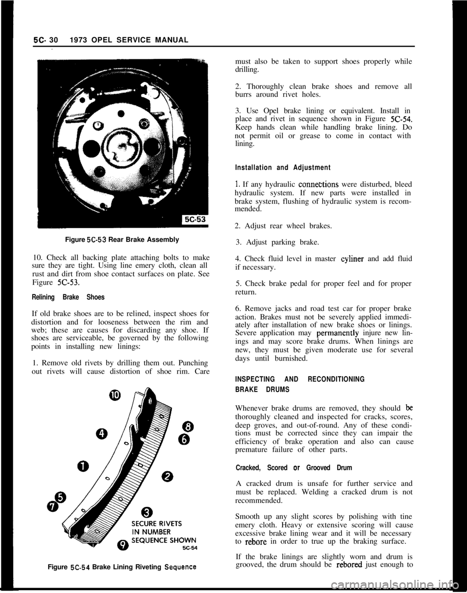
Figure 5C-53 Rear Brake Assembly
10. Check all backing plate attaching bolts to make
sure they are tight. Using line emery cloth, clean all
rust and dirt from shoe contact surfaces on plate. See
Figure Z-53.
Relining Brake ShoesIf old brake shoes are to be relined, inspect shoes for
distortion and for looseness between the rim and
web; these are causes for discarding any shoe. If
shoes are serviceable, be governed by the following
points in installing new linings:
1. Remove old rivets by drilling them out. Punching
out rivets will cause distortion of shoe rim. Care5C- 301973 OPEL SERVICE MANUAL
must also be taken to support shoes properly while
drilling.
2. Thoroughly clean brake shoes and remove all
burrs around rivet holes.
3. Use Opel brake lining or equivalent. Install in
place and rivet in sequence shown in Figure
Z-54.Keep hands clean while handling brake lining. Do
not permit oil or grease to come in contact with
lining.
Installation and Adjustment
1. If any hydraulic conne&tions were disturbed, bleed
hydraulic system. If new parts were installed in
brake system, flushing of hydraulic system is recom-
mended.
2. Adjust rear wheel brakes.
3. Adjust parking brake.
4. Check fluid level in master cyliner and add fluid
if necessary.
5. Check brake pedal for proper feel and for proper
return.
6. Remove jacks and road test car for proper brake
action. Brakes must not be severely applied immedi-
ately after installation of new brake shoes or linings.
Severe application may perinanently injure new lin-
ings and may score brake drums. When linings are
new, they must be given moderate use for several
days until burnished.
INSPECTING AND RECONDITIONING
BRAKE DRUMSWhenever brake drums are removed, they should
bethoroughly cleaned and inspected for cracks, scores,
deep groves, and out-of-round. Any of these condi-
tions must be corrected since they can impair the
efficiency of brake operation and also can cause
premature failure of other parts.
Cracked, Scored or Grooved DrumA cracked drum is unsafe for further service and
must be replaced. Welding a cracked drum is not
recommended.
Smooth up any slight scores by polishing with tine
emery cloth. Heavy or extensive scoring will cause
excessive brake lining wear and it will be necessary
to rebore in order to true up the braking surface.
Figure 5C.54 Brake Lining Riveting
SequenceIf the brake linings are slightly worn and drum is
grooved, the drum should be rebored just enough to