ECO mode OPEL GT-R 1973 Owner's Manual
[x] Cancel search | Manufacturer: OPEL, Model Year: 1973, Model line: GT-R, Model: OPEL GT-R 1973Pages: 625, PDF Size: 17.22 MB
Page 534 of 625
REFRIGERANT COMPONENTS ALL MODELS9B- 2596.15
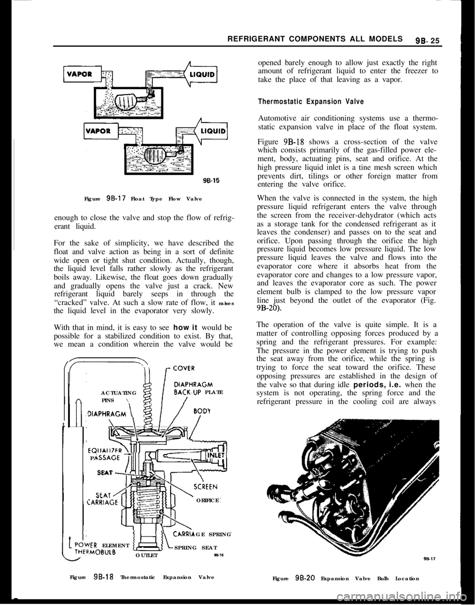
Figure 95.17 Float Type Flow Valve
enough to close the valve and stop the flow of refrig-
erant liquid.
For the sake of simplicity, we have described the
float and valve action as being in a sort of definite
wide open or tight shut condition. Actually, though,
the liquid level falls rather slowly as the refrigerant
boils away. Likewise, the float goes down gradually
and gradually opens the valve just a crack. New
refrigerant liquid barely seeps in through the
“cracked” valve. At such a slow rate of flow, it raises
the liquid level in the evaporator very slowly.
With that in mind, it is easy to see how it would be
possible for a stabilized condition to exist. By that,
we mean a condition wherein the valve would be/
DIAPHRAGMACTUATINGBACK.UP PLATE
PINS \
t
>IAPHRAGM \
/
BoDyEQUALIZER\4]
PASSAGE
‘!!!ISEATSCkEEN:ARRIAGEORIFICE
AGE SPRINGIER ELEMENT:MOB”LBSPRING SEAT
OUTLET
W-16opened barely enough to allow just exactly the right
amount of refrigerant liquid to enter the freezer to
take the place of that leaving as a vapor.
Thermostatic Expansion ValveAutomotive air conditioning systems use a thermo-
static expansion valve in place of the float system.
Figure 9B-18 shows a cross-section of the valve
which consists primarily of the gas-filled power ele-
ment, body, actuating pins, seat and orifice. At the
high pressure liquid inlet is a tine mesh screen which
prevents dirt, tilings or other foreign matter from
entering the valve orifice.
When the valve is connected in the system, the high
pressure liquid refrigerant enters the valve through
the screen from the receiver-dehydrator (which acts
as a storage tank for the condensed refrigerant as it
leaves the condenser) and passes on to the seat and
orifice. Upon passing through the orifice the high
pressure liquid becomes low pressure liquid. The low
pressure liquid leaves the valve and flows into the
evaporator core where it absorbs heat from the
evaporator core and changes to a low pressure vapor,
and leaves the evaporator core as such. The power
element bulb is clamped to the low pressure vapor
line just beyond the outlet of the evaporator (Fig.
9B-20).The operation of the valve is quite simple. It is a
matter of controlling opposing forces produced by a
spring and the refrigerant pressures. For example:
The pressure in the power element is trying to push
the seat away from the orifice, while the spring is
trying to force the seat toward the orifice. These
opposing pressures are established in the design of
the valve so that during idle periods, i.e. when the
system is not operating, the spring force and the
refrigerant pressure in the cooling coil are always
Figure 9B-18 Thermostatic Expansion Valve
Figure
98.20 Expansion Valve Bulb Location
Page 538 of 625
REFRIGERANT COMPONENTS ALL MODELS99.29
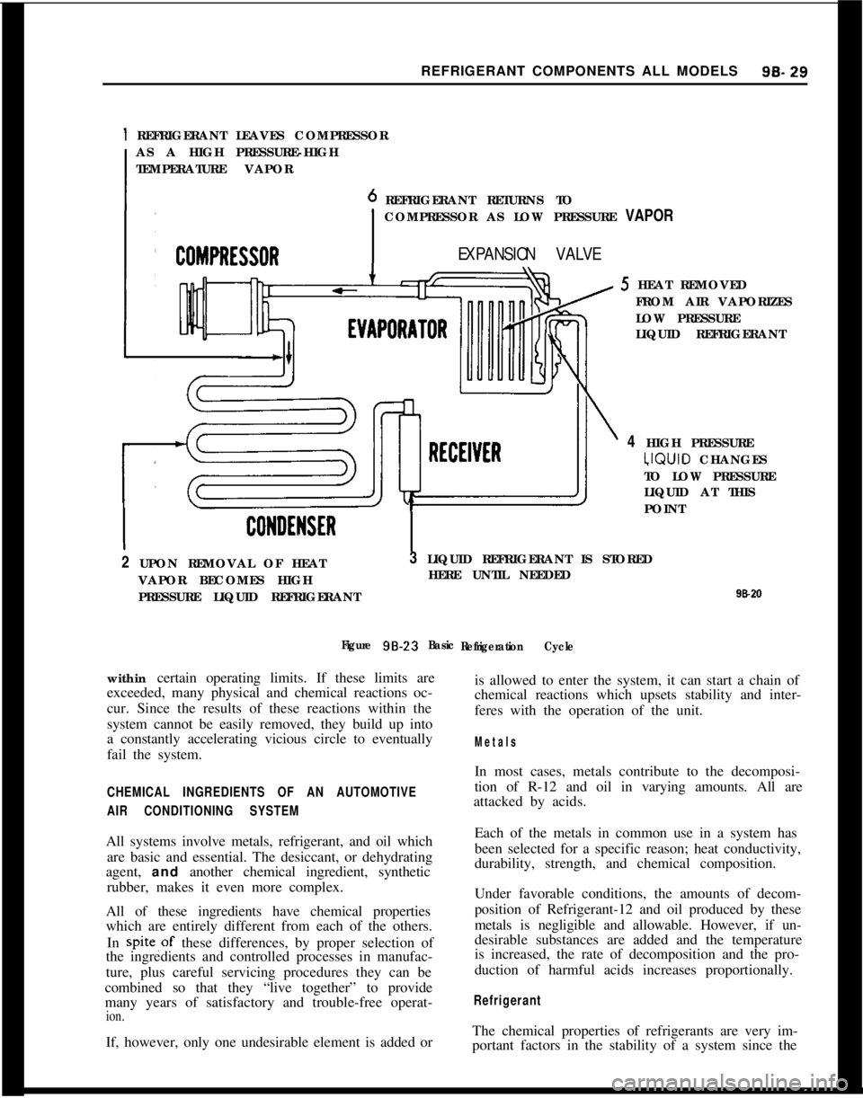
1 REFRIGERANT LEAVES COMPRESSOR
AS A HIGH PRESSURE-HIGH
TEMPERATURE VAPOR
REFRIGERANT RETURNS TO
COMPRESSOR AS LOW PRESSURE VAPOR
EXPANSION VALVE5 HEAT REMOVED
FROM AIR VAPORIZES
LOW PRESSURE
LIQUID REFRIGERANT
4 HIGH PRESSURE‘JQUID CHANGES
TO LOW PRESSURE
LIQUID AT THIS
POINT
2 UPON REMOVAL OF HEAT
VAPOR BECOMES HIGH
PRESSURE LIQUID REFRIGERANT3 LIQUID REFRIGERANT IS STORED
HERE UNTIL NEEDED
98*II
Figure 98-23
Basic
Refrigeration Cyclewithin certain operating limits. If these limits are
exceeded, many physical and chemical reactions oc-
cur. Since the results of these reactions within the
system cannot be easily removed, they build up into
a constantly accelerating vicious circle to eventually
fail the system.is allowed to enter the system, it can start a chain of
chemical reactions which upsets stability and inter-
feres with the operation of the unit.
Metals
CHEMICAL INGREDIENTS OF AN AUTOMOTIVE
AIR CONDITIONING SYSTEMAll systems involve metals, refrigerant, and oil which
are basic and essential. The desiccant, or dehydrating
agent, and another chemical ingredient, synthetic
rubber, makes it even more complex.
All of these ingredients have chemical properties
which are entirely different from each of the others.
In spite,of these differences, by proper selection of
the ingredients and controlled processes in manufac-
ture, plus careful servicing procedures they can be
combined so that they “live together” to provide
many years of satisfactory and trouble-free operat-
ion.If, however, only one undesirable element is added orIn most cases, metals contribute to the decomposi-
tion of R-12 and oil in varying amounts. All are
attacked by acids.
Each of the metals in common use in a system has
been selected for a specific reason; heat conductivity,
durability, strength, and chemical composition.
Under favorable conditions, the amounts of decom-
position of Refrigerant-12 and oil produced by these
metals is negligible and allowable. However, if un-
desirable substances are added and the temperature
is increased, the rate of decomposition and the pro-
duction of harmful acids increases proportionally.
RefrigerantThe chemical properties of refrigerants are very im-
portant factors in the stability of a system since the
Page 540 of 625
REFRIGERANT COMPONENTS ALL MODELS9B- 31
When adding oil, the container should be exception-
ally clean and dry due to the fact that the refrigera-
tion oil in the container is as moisture-free as it is
possible to make it. Therefore, it will quickly absorb
any moisture with which it comes in contact. For this
same reason the oil container should not be opened
until ready for use and it should be capped immedi-
ately afte;r use.
When it is necessary to open a system, have every-
thing you will need ready and handy so that as little
time as possible will be required to perform the oper-
ation. Don’t leave the system open any longer than
is necessary.
Finally, after the operation has been completed and
the system sealed again, air and moisture should be
evacuated from the system before recharging.
THE PRIMARY CAUSES OF SYSTEM FAILURES
LeaksA shortage of refrigerant causes oil to be trapped in
the evaporator. Oil may be lost with the refrigerant
at point of leakage. Both of these can cause compres-
sor seizure.
Oil circulates in the system with the refrigerant; in
solution with the liquid and in globules with the
vapor. It leaves the compressor by the action of the
pistons and mixes with the refrigerant liquid in the
condenser. The oil then enters the evaporator with
the liquid and, with the evaporator properly flooded,
is returned to the compressor through the low pres-
sure line. Some of the oil returns as globules in the
vapor, but more important, it is swept as a liquid
along the walls of the tubing by the velocity of the
vapor. If the evaporator is starved, the oil cannot
return in sut?icient quantities to keep the compressor
properly lubricated.
High Temperature and PressureAn increase in temperature causes an increase in
pressure. This accelerates chemical instability due to
existing contaminants in the system, and initiates
chemical instability in clean systems. Other results
are brittle hoses,
“0” ring gaskets, and valve dia-
phragms with possible decomposition, broken com-
pressor discharge reeds, and seized compressor
bearings.
A fundamental law of nature accounts for the fact
that when a substance, such as a refrigerant, is in-
creased in temperature, its pressure is also increased.
Any chemical reactions caused by contaminants al-
ready in the system are greatly accelerated as the
temperature increases. A 15 degree rise in tempera-
ture doubles the chemical action. Even in a goodclean system, heat alone can start a chain of harmful
chemical reactions.
While temperature alone can cause the synthetic rub-
ber parts to become brittle and possibly to decom-
pose, the increased pressure can cause them to
rupture or blow.
As the temperature and pressure increases the stress
and strain on the compressor discharge reeds also
increases. This can result in broken reeds. Due to the
effect of the contaminants caused by high tempera-
ture and pressure, compressor bearings can be
caused to seize.
High temperature and pressure are also caused by air
in the system.
Air in the SYstemAir results from a discharged system or careless ser-
vicing procedures. This reduces system capacity and
efficiency and causes oxidation of oil into gum and
varnish.
When a leak causes the system to become dis-
charged, the resulting vacuum within the system will
cause air to be drawn in. Air in the system is a
non-condensable gas and will build up in the con-
denser as it would in an air compressor tank. The
resultant heat produced will contribute to the condi-
tions discussed previously.
Many systems are contaminated and also reduced in
capacity and efficiency by servicemen who either do
not know or are careless regarding proper servicing
procedures.
Too frequently, systems which have been open to the
atmosphere during service operations have not been
properly purged or evacuated. Air is also introduced
into the system by unpurged gauge and charging
lines. Remember that any air in the system is too
much air.
Poor ConnectionsHose clamp type fittings must be properly made.
Hoses should be installed over the sealing flanges and
with the end of the hose at the stop flange. The hose
should never extend beyond the stop flange. Locate
the clamp properly and torque as recommended. Be
especially careful that the sealing flanges are not
nicked or scored or a future leak will result.
When compression fittings are used, over tightening
can cause physical damage to the “0” ring gasket
and will result in leaks. The use of torque and back-
ing wrenches is highly recommended. When making
a connection with compression fittings, the gaskets
should always be first placed over the tube before
Page 544 of 625
REFRIGERANT COMPONENTS ALL MODELS9s. 35
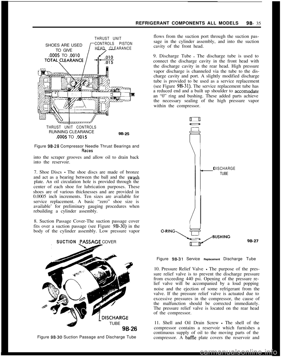
THRUST UNITSHOES ARE USED
CONTROLS PISTONTO GIVE
HEAD CLEARANCE
.0005 TO .OOlOTOTAL\CLEARANCE
THRUST UNIT CONTROLSRUNNING CLEARANCE.0005 TO .0015
9B-25Figure 98-28 Compressor Needle Thrust Bearings and
into the scraper grooves and allow oil to drain back
into the reservoir.
7. Shoe Discs
- The shoe discs are made of bronze
and act as a bearing between the ball and the wash
plate. An oil circulation hole is provided through the
center of each shoe for lubrication purposes. These
shoes are of various thicknesses and are provided in
0.0005 inch increments. Ten sizes are available for
service replacement. A basic “zero” shoe size is
available’ for preliminary gauging procedures when
rebuilding a cylinder assembly.
8. Suction Passage Cover-The suction passage cover
fits over a suction passage (see Figure 9B-30) in the
body of the cylinder assembly. Low pressure vapor
SUCTION PASSAGECOVER
TUBE9B-26
Figure 98-30 Suction Passage and Discharge Tubeflows from the suction port through the suction pas-
sage in the cylinder assembly, and into the suction
cavity of the front head.
9. Discharge Tube
- The discharge tube is used to
connect the discharge cavity in the front head with
the discharge cavity in the rear head. High pressure
vapor discharge is channeled via the tube to the dis-
charge cavity and port. A slightly modified discharge
tube is provided to be used as a service replacement
(see Figure
9B-31). The service replacement tube has
a reduced end and a built up shoulder to accomodate
an “0” ring and bushing. These added parts achieve
the necessary sealing of the high pressure vapor
within the compressor.
DISCHARGE
TUBE
oeR’NG\s~~~~~~G98.27
Figure 98.31 Service Replacement Discharge Tube
10. Pressure Relief Valve
- The purpose of the pres-
sure relief valve is to prevent the discharge pressure
from exceeding 440 psi. Opening of the pressure re-
lief valve will be accompanied by a loud popping
noise and the ejection of some refrigerant from the
valve. If the pressure relief valve is actuated due to
excessive pressures in the compressor, the cause of
the malfunction should be corrected immediately.
The pressure relief valve is located on the rear head
of the compressor.
11. Shell and Oil Drain Screw
- The shell of the
compressor contains a reservoir which furnishes a
continuous supply of oil to the moving parts of the
compressor. A
batTIe plate covers the reservoir and
Page 546 of 625
REFRIGERANT COMPONENTS ALL MODELS
99.37
in front of the radiator so that it receives a high
volume of air flow. Air passing over the condenser
absorbs the heat from the high pressure gas and
causes the refrigerant to condense into a high pres-
sure liquid.Receiver. DehydratorThe receiver-dehydrator is located in the engine
compartment. The purpose of the receiver dehydra-
tor is two fold: the unit insures a solid column of
liquid refrigerant to the expansion valve at all times,
and also absorbs any moisture in the system that
might be present. A bag of desiccant (moisture ab-
sorbing material) is provided to absorb moisture. A
sight glass (see Figure 9B-33) permits visual check-
ing of the refrigerant flow for bubbles or foam. The
continuous appearance of bubbles or foam above an
ambient temperature of 70 degrees F. usually indi-
cates an inadequate refrigerant charge. Bubbles or
foam appearing at ambient temperatures below 70
degrees F. do not necessarily indicate an inadequate
charge and may appear even when the system is
operating properly. A filter screen in the unit pre-
vents foreign material from entering the remainder
of the system.
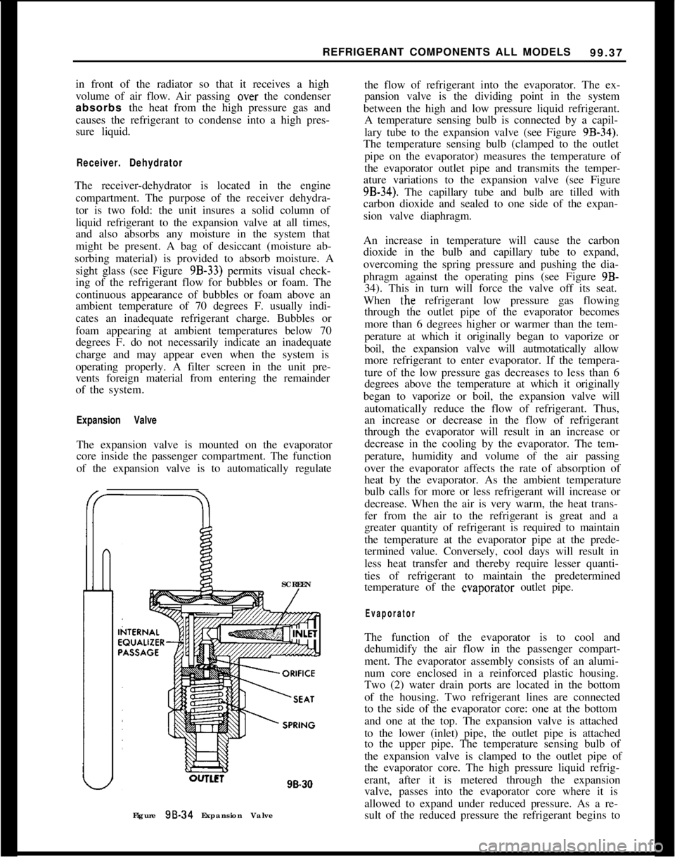
Expansion ValveThe expansion valve is mounted on the evaporator
core inside the passenger compartment. The function
of the expansion valve is to automatically regulate
SCREEN
lLCl98.30
Figure 98-34 Expansion Valvethe flow of refrigerant into the evaporator. The ex-
pansion valve is the dividing point in the system
between the high and low pressure liquid refrigerant.
A temperature sensing bulb is connected by a capil-
lary tube to the expansion valve (see Figure
9B-34).The temperature sensing bulb (clamped to the outlet
pipe on the evaporator) measures the temperature of
the evaporator outlet pipe and transmits the temper-
ature variations to the expansion valve (see Figure
9B-34). The capillary tube and bulb are tilled with
carbon dioxide and sealed to one side of the expan-
sion valve diaphragm.
An increase in temperature will cause the carbon
dioxide in the bulb and capillary tube to expand,
overcoming the spring pressure and pushing the dia-
phragm against the operating pins (see Figure 9B-
34). This in turn will force the valve off its seat.
When the refrigerant low pressure gas flowing
through the outlet pipe of the evaporator becomes
more than 6 degrees higher or warmer than the tem-
perature at which it originally began to vaporize or
boil, the expansion valve will autmotatically allow
more refrigerant to enter evaporator. If the tempera-
ture of the low pressure gas decreases to less than 6
degrees above the temperature at which it originally
began to vaporize or boil, the expansion valve will
automatically reduce the flow of refrigerant. Thus,
an increase or decrease in the flow of refrigerant
through the evaporator will result in an increase or
decrease in the cooling by the evaporator. The tem-
perature, humidity and volume of the air passing
over the evaporator affects the rate of absorption of
heat by the evaporator. As the ambient temperature
bulb calls for more or less refrigerant will increase or
decrease. When the air is very warm, the heat trans-
fer from the air to the refrigerant is great and a
greater quantity of refrigerant is required to maintain
the temperature at the evaporator pipe at the prede-
termined value. Conversely, cool days will result in
less heat transfer and thereby require lesser quanti-
ties of refrigerant to maintain the predetermined
temperature of the evaporator outlet pipe.
EvaporatorThe function of the evaporator is to cool and
dehumidify the air flow in the passenger compart-
ment. The evaporator assembly consists of an alumi-
num core enclosed in a reinforced plastic housing.
Two (2) water drain ports are located in the bottom
of the housing. Two refrigerant lines are connected
to the side of the evaporator core: one at the bottom
and one at the top. The expansion valve is attached
to the lower (inlet) pipe, the outlet pipe is attached
to the upper pipe. The temperature sensing bulb of
the expansion valve is clamped to the outlet pipe of
the evaporator core. The high pressure liquid refrig-
erant, after it is metered through the expansion
valve, passes into the evaporator core where it is
allowed to expand under reduced pressure. As a re-
sult of the reduced pressure the refrigerant begins to
Page 548 of 625
REFRIGERANT COMPONENTS ALL MODELS96-39
In all instances where the indications of refrigerant
shortage continues, additional refrigerant should be
added in
l/4 lb. increments until the sight glass is
clear.
An additional charge of l/4 lb. should be ad-
ded as a reserve. In no case should the system be
overcharged.
LEAK TESTING SYSTEM
The following two methods are recommended when attempting to locate refrigerant leaks in the system.
Loss of
regrigerant is always indicative of a leak since
refrigerant is not consumed and does not wear out.
1. Open Flame Method
- This method utilizes a gas
operated torch type leak detector (J-6084). Use of
this method is recommended when checking for
leaks in confined areas. To perform test, light torch
and adjust to obtain a pale blue flame, approximately
3/8 inch in height, in burner.
Explore for leaks by moving end of search tube
around suspected area. Check bottom of connections
since Refrigerant-12 is heavier than air and will be more apparent at underside of fittings. The flame
color will turn yellow-green when a small leak is
detected. Large leaks will turn the flame blue or
purple.
WARNING:
Do not breathe fumes resdting from
burning of
refrigerant gas. These fumes az ex-
tremeiy poisonous.
2. Liquid Leak Detectors - This method utilizes a
solution which will bubble (soap solution) to signify
a gas leak. Use of this method of checking is recom-
mended for locating small leaks.
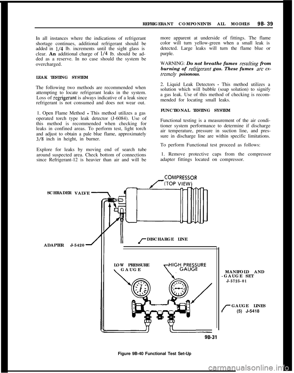
FUNCTIONAL TESTING SYSTEM
Functional testing is a measurement of the air condi-
tioner system performance to determine if discharge
air temperature, pressure in suction line, and pres-
sure in discharge line are within specific limitations.
To perform Functional test proceed as follows:
1. Remove protective caps from the compressor
adapter fittings located on compressor.
SCHRADER
ADAPTER J-5420
1II rDISCHARGE LINE
COMPRESSOR
VALVE
LOW PRESSURE
\ GAUGE\
HIGHGLR;B;URE
MANIFOLD AND
-GAUGE SET
J-5725-01
r
GAUGE LINES
(5) J-5418
9B-31
Figure 9B-40 Functional Test Set-Up
Page 550 of 625
REFRIGERANT COMPONENTS ALL MODELS9s. 41
BIower Operating Normal Check for the following:Restriction or leakage in air ducts, A/C outlets not
opening.2. Do not carry cylinder in passenger compartment
of car.3. Do not subject cylinder to high temperatures.
MAINTENANCE AND ADJUSTMENTS4. Do not weld or steam clean on or near cylinder.
5. Do not fill cylinder completely.
GENERAL SERVICE INFORMATION AND SAFETY
PRECAUTIONS6. Do not discharge vapor into area where flame is
exposed or directly into engine air intake.
General InformationAll subassemblies are shipped sealed and dehy-
drated. They are to remain sealed until just prior to
making connections, and should be at room tempera-
ture before uncapping. This prevents condensation of
moisture from air that enters the system.
All precautions should be taken to prevent damage
to fittings or connections. Even minute damage to a
connection could cause it to leak. Any fittings with
grease or dirt on them should be wiped clean with a
cloth dipped in alcohol.
Do not clean fitting or hoses with solvents because
they are contaminants. If dirt, grease or moisture
gets inside the pipes or hoses and cannot be removed,the pipe or hose is to be replaced. Use a small amount
of clean refrigeration oil on all tube and hose con-
necting joints, and lubricate the
“0” ring gasket with
this oil before assembling the joint. The oil will help
in effectitig a leak-proofjoint and assist the
“0” ring
to slip into the proper location without being cut or
damaged. Always use new
“0” rings.
When tightening joints, use a second wrench to hold
the stationary part of the connection to prevent
twisting and to prevent hose kinking. Kinked hoses
are apt to transmit noise and vibration. Tighten all
connections in accordance with recommended
torques (see Division VI, Specifications).7. Do not expose eyes to liquid
- WEAR SAFETY
GOGGLES whenever discharging, charging or leak
testing system.
CHARGING AND DISCHARGING SYSTEMRemoval of any part in the refrigerant circuit will
require discharging of the entire system.
Discharging the System1. Remove caps from gauge fittings on the compres-
sor adapter fitting on the compressor.
2. With both valves on manifold gauge set (J-5725-
04) closed (clockwise), attach manifold to the com-
pressor adapter fitting on the compressor, using
J-5420 valve adapter at suction gauge fitting and
J-9459 valve adapter at discharge gauge fitting. See
Figure
9B-41.3. Fully open high pressure valve on manifold gauge
set to allow escape of refrigerant from system
through the manifold gauge set and out the center
fitting and hose. (Place end of hose in clean container
to collect oil loss due to rapid discharge of system).
4. When hissing ceases, indicating all refrigerant
has escaped, close high pressure valve on manifold
gauge set by turning valve clockwise.
Do not connect receiver-dehydrator assembly until
all other connections have been made. This is neces-
sary to itisure maximum moisture removal from sys-
tem.It is important that air conditioning hoses do not rest
on or contact body sheet metal except where neces-
sary. Because of the high frequency at which the
compressor operates, the passenger compartment is
susceptible to transfer of noise.
Evacuating the SystemWhen the refrigeration system is depressurized and
opened for service, some air will enter the lines, re-
gardless of how quickly openings are capped. In
or-der to remove this air and as much as possible of the
moisture it contains, the complete system must be
evacuated. Evacuating is merely the process of
removing all air from the system, thereby creating a
vacuum in the system.
Safety PiecautionsThe following safety precautions should always be
followed~,when servicing refrigerant charged compo-nents:Under no circumstances should alcohol be used in
the system in an attempt to remove moisture,
regard-less of the successful use of alcohol in other refrigera-
tion systems.
Preparations for Evacuating Complete System
1. Do not leave Refrigerant-12 cylinder uncapped.
1. Check the low pressure gauge for proper calibra-
Page 554 of 625
REFRIGERANT COMPONENTS ALL MODELS9t3- 45
B. If system is charged using J-6272-02, close the
valve of opener after all cans are empty. Release the locking lever and discard the three (3) empty cans.
If this tool will be used to complete the charge with
additional cans to provide the required refrigerant
charge, leave the empty cans in position, locate one
full can and lock the lever into place. These empty
cans balance the assembly and prevent the loss of
refrigerant through the open “series” passage. Align
the pierced hole in the empty can with the punch in
the cover of the tool.
If the J-6271 valve for single cans is available, com-
plete charging as explained in 4a above.
5. Close high side valve on manifold gauge set,
WARNING: Prior to starting up engine, the high side
valve on the charging manifold must be closed due
to excessive pressure
bui/d-up which can result in
bursting of the container(s) causing serious injury. If
you are inexperienced in the use of this procedure, seek professional assistance.
6. Operate engine at 2000 RPM with temperature
control knob at full cold position and blower speed
on Max Hi. If air inlet temperature at the condenser
is below 70 degrees F. when this check is made,
bubbles may appear, even though the proper amount
of refrigerant is in the system. Air inlet temperature
must be 70 degrees F. or above to make an accurate
check.
7. When refrigerant has been installed, continue to
operate system and test for proper operation as ou-
tlined
under “Operational Test”.
8. When satisfied that the air conditioning system
is operating properly, stop engine, remove gauge set
and replace protective caps on suction and discharge
fittings.
from thegauge fitting to prevent damage-or injury to
personnel.
9. Using a leak detector, check complete system for
leaks.
Charging Station Method
INSTALLING J-8393-02
-
1. Be ceitain compressor hand shut-off valves to
gauge fittings are closed (counterclockwise).
2. Be certain all valves on charging station are
closed.
3. Connect high pressure gauge line to compressor
high pressure gauge fitting.
4. Turn high pressure hand shut-off valve one turn
clockwise, and high pressure control one turn coun-
terclockwise (open). Crack open low pressure con-
trol and allow refrigerant gas to hiss from low
pressure gauge line for three seconds, then connect
low pressure gauge line to low pressure gauge fitting
on compressor adapter fitting. (Place J-9459 adapter
on hose, then attach adapter to gauge fitting.)
FILLING CHARGING CYLINDER
1. Open Control valve on refrigerant container.
2. Open valve on bottom of charging cylinder, al-
lowing refrigerant to enter cylinder.
3. Bleed charging cylinder to valve (behind control
panel) only as required to allow refrigerant to enter
cylinder. When refrigerant reaches desired charge
level, close valve at bottom of charging cylinder and
be certain cylinder bleed valve is closed securely.
While filling the cylinder, it will be necessary to close
the bleed valve periodically to allow boiling to sub-
side so that refrigerant level in the charging cylinder
can be accurately read.
CHARGING THE SYSTEM USING J-8393-02
1. With charging station connected, as previously
described, remove low pressure gauge line at com-
pressor adapter fitting.
2. Crack open high and low pressure control valves
on station and allow refrigerant gas to purge from
system. Purge slowly enough so, that oil does not
escape from system along with refrigerant.
3. When refrigerant flow nearly stops, connect low
pressure gauge line to
compress& adapter fitting.
4. Turn on vacuum pump and open vacuum control
valve.
5. With system purged as
abovk, run pump until
26-28 inches of vacuum is obtained Continue to run
pump for 15 minutes after the system reaches 26-28
inches vacuum.
In all evacuating procedures, the specification of
26.
28 inches of mercury vacuum is used. These figures
are only attainable at or near sea level. For each 1000
feet above sea level where this operation is being
performed, the specifications should be lowered by 1
inch. For example, at 5000 feet elevation, only 21 to
23 inches vacuum can normally be obtained.
6. If 26-28 inches vacuum (corrected to sea level)
cannot be obtained, close vacuum: control valve and
Page 556 of 625

REFRIGERANT COMPONENTS ALL MODELS9a- 47
B. Connect center flexible line of gauge set to the
fitting on the valve.
C. Start engine, turn temperature control knob to full
cold position, set blower switch to Max Hi. Operate
engine for 10 minutes at 2000 RPM to stabilize sys-tem.D. With compressor operating, slowly open valve on
refrigerant can and allow refrigerant to flow into
system (through manifold gauge set) until liquid in-
dicator clears up and immediately shut off valve at
gauge set and on refrigerant can. Check weight of
can and valve assembly and record.
E. Add an additional 1 lb. of refrigerant by adding
refrigerant from the can just weighed until can is
empty. Attach another can and add refrigerant until
can and valve assembly weigh the same as recorded.
6. Close valves at refrigerant drum or
can,7. Test for leaks and make operational check of
system.
ADDING OIL TO THE SYSTEM (MAJOR
OVERHAUL)The oil in the refrigeration system does not remain
in the compressor during system operation, but cir-culates throughout the system. The compressor is
initially charged with 10 oz. of 525 viscosity oil.
After system has been in operation the oil content in
the compressor will vary depending on the engine
RPM and air conditioning load. At higher engine
RPM’s a lesser amount of oil will be retained in the
compressor reservoir. It is important that the total
system oil content does not vary from a total of10-l/2 oz. Excessive oil content will reduce cooling
capacity. Inadequate oil content may result in dam-
age to compressor moving parts.
The refrigeration system will not require adding of
oil unless there is an oil loss because of a ruptured
line, badly leaking compressor seal, replacement of
evaporator, compressor, receiver-dehydrator, or loss
due to a collision. Oil is generally added to the sys-
tem via the oil drain hole in the lower side of the
compressor for this condition. To add oil to the sys-
tem via the compressor, the compressor must be
removed. If no major loss of oil has occurred and a
component (condenser,receiver-dehydrator or
evaporator) is removed for servicing, the oil may be
added directly to the component. To add oil to a
component removed for servicing and when no ma-
jor loss has occurred, drain and measure oil in com-
ponent, then replace with a like amount. To add oil
to the system when a major loss of oil is evidenced,
or when the compressor is being serviced, remove
compressor, drain and measure oil, and replace oil
amount specified in the Oil Replacement Table.
OIL REP,‘LACEMENT TABLE
Condition
1. Major loss of oil and
a component (conden-
ser, receiver-dehydra-
tor, or evaporator)
has to be replaced.
Amount of Oil Drained
From Compressora. More than 4 oz.Amount of 525 Oil to Install
In Compressora. Amount drained from compressor,
plus amount for component
being replaced.
Evaporator
- Add 2 oz.
Condenser
- Add I oz.
Receiver-Dehydrator
- Add 1 oz.
b. Less than 4 oz.b. Install 6 oz., plus amount for
component being replaced as
shown above.
2. Compressor being
replaced with a
ser-vice replacement
compressor
- no major
oil loss.a. More than 1
l/2 oz.a. Same amount as drained from
compressor being replaced.
b. Less than 1
l/2 oz.b. Install 6 oz
Page 562 of 625
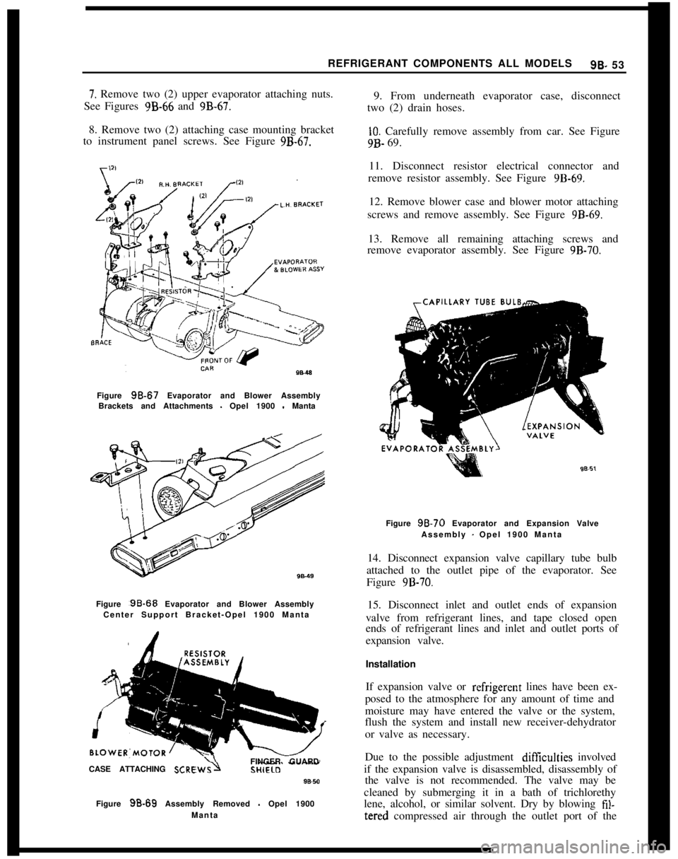
REFRIGERANT COMPONENTS ALL MODELS9B- 537. Remove two (2) upper evaporator attaching nuts.
See Figures 9B-66 and 9B-67.
8. Remove two (2) attaching case mounting bracket
to instrument panel screws. See Figure
9B-67.Figure
98.67 Evaporator and Blower Assembly
Brackets and Attachments - Opel 1900 - Manta
Figure :9B-68 Evaporator and Blower Assembly
Center Support Bracket-Opel 1900 Manta
CASE ATTACHING
SCREFINGER GUARD
Figure
98.69 Assembly Removed - Opel 1900
Manta9. From underneath evaporator case, disconnect
two (2) drain hoses.
10. Carefully remove assembly from car. See Figure9B- 69.
11. Disconnect resistor electrical connector and
remove resistor assembly. See Figure
9B-69.12. Remove blower case and blower motor attaching
screws and remove assembly. See Figure
9B-69.13. Remove all remaining attaching screws and
remove evaporator assembly. See Figure
9B-70.Figure
98.70 Evaporator and Expansion Valve
Assembly
- Opel 1900 Manta
14. Disconnect expansion valve capillary tube bulb
attached to the outlet pipe of the evaporator. See
Figure
9B-70.15. Disconnect inlet and outlet ends of expansion
valve from refrigerant lines, and tape closed open
ends of refrigerant lines and inlet and outlet ports of
expansion valve.
Installation
If expansion valve or refrigerent lines have been ex-
posed to the atmosphere for any amount of time and
moisture may have entered the valve or the system,
flush the system and install new receiver-dehydrator
or valve as necessary.
Due to the possible adjustment difficulties involved
if the expansion valve is disassembled, disassembly of
the valve is not recommended. The valve may be
cleaned by submerging it in a bath of trichlorethy
lene, alcohol, or similar solvent. Dry by blowing fil-tered compressed air through the outlet port of the