lock OPEL GT-R 1973 Service Manual
[x] Cancel search | Manufacturer: OPEL, Model Year: 1973, Model line: GT-R, Model: OPEL GT-R 1973Pages: 625, PDF Size: 17.22 MB
Page 329 of 625
6C- 381973 OPEL SERVICE MANUALCAUTION:Because the fuel pump is below fuel tank
level, fuel
will drain from the tank. when the supply
hne is disconnected from the fuel pump.1. Pull fuel supply line and rubber connector from
fuel pump. Plug rubber connector to prevent fuel
loss.2. Remove fuel pump cap, gasket and plastic
strainer.
3. Cover center opening in sediment bowl with finger
and blow out sediment bowl with compressed air.
4. Wash plastic strainer in solvent; if strainer does
not clean-up or is damaged, replace strainer.
5. Install clean parts, noting the following:
(a) Strainer must be properly seated with projections
facing upward.(b) A new cap gasket must be positioned over
strainer.
(c) Sealing ring must be in place on cap retaining
screw.6. Reconnect fuel supply line. Start engine and check
for leaks.
EVAPORATION CONTROL SYSTEMProper performance of the system requires the use of
a non-vented fuel tank cap, hose connections be leak-
free, and all hoses routed correctly to avoid a
pinched or blocked line.
Maintenance requirements demand only that the ac-
cumulator purge air tilter, an oiled foam filter assem-
bled in the bottom of the canister, be replaced at
12,CKO mile intervals. Under extremely dusty condi-
tions, more frequent attention may be required.
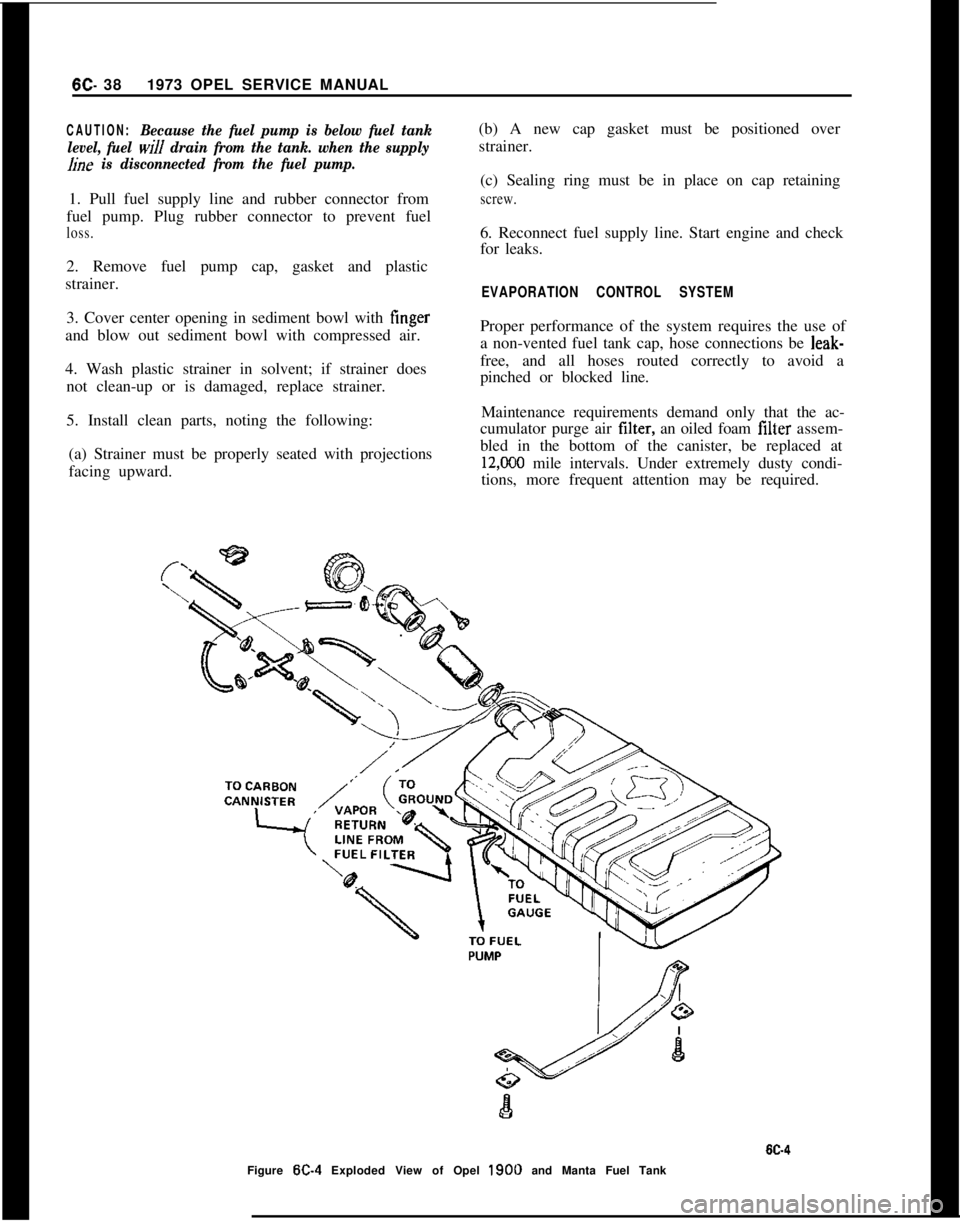
Figure
W-4 Exploded View of Opel 1900 and Manta Fuel Tank
Page 341 of 625
6E- 501973 OPEL SERVICE MANUALMAINTENANCE AND ADJUSTMENTS
IDLE SPEED ADJUSTMENT
Note:
Idle speeds of 600 to 800 R.P.M. are normal
for engines with less than
3,ooO miles.Prior to making any adjustment to the carburetor,
the following items must be checked for proper oper-
ation and/or setting:
1. Valve Adjustment (Hydraulic lifters can be im-
properly adjusted.)
2. Dwell Angle.
3. Ignition Timing.
4. Spark Plug Gap.
5. Exhaust Gas Recirculation Valve (See “Check-
ing” under EXHAUST GAS RECIRCULATION
SYSTEM.)
After it has been ascertained that the above items are
properly adjusted and operating correctly and idle
R.P.M. is still not within specifications, proceed as
follows:
1. With air cleaner installed, run engine until normal
operating temperature is reached.
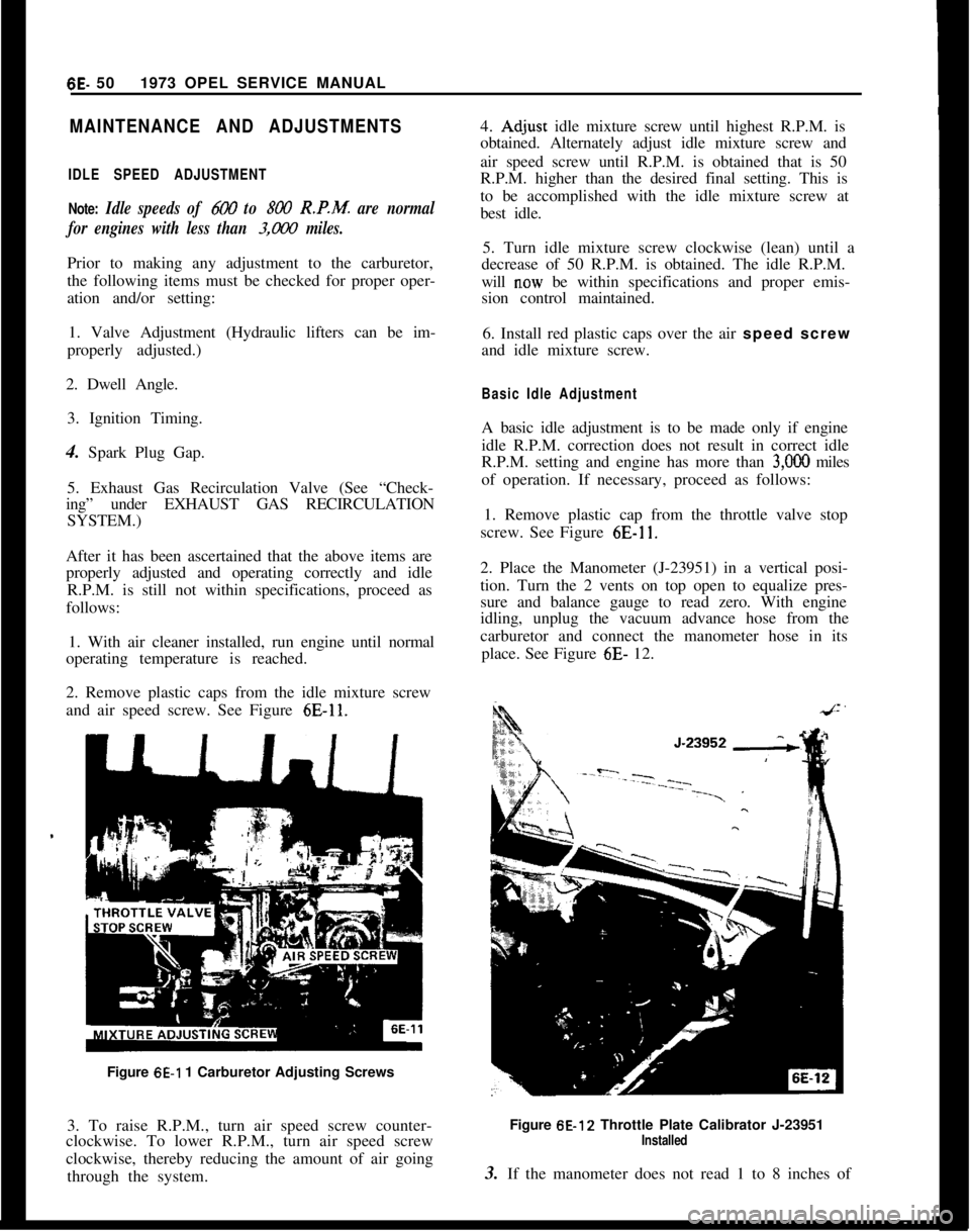
2. Remove plastic caps from the idle mixture screw
and air speed screw. See Figure
6E-11.Figure
6E-1 1 Carburetor Adjusting Screws
3. To raise R.P.M., turn air speed screw counter-
clockwise. To lower R.P.M., turn air speed screw
clockwise, thereby reducing the amount of air going
through the system.4.
Ad,just idle mixture screw until highest R.P.M. is
obtained. Alternately adjust idle mixture screw and
air speed screw until R.P.M. is obtained that is 50
R.P.M. higher than the desired final setting. This is
to be accomplished with the idle mixture screw at
best idle.
5. Turn idle mixture screw clockwise (lean) until a
decrease of 50 R.P.M. is obtained. The idle R.P.M.
will
n.ow be within specifications and proper emis-
sion control maintained.
6. Install red plastic caps over the air speed screw
and idle mixture screw.
Basic Idle AdjustmentA basic idle adjustment is to be made only if engine
idle R.P.M. correction does not result in correct idle
R.P.M. setting and engine has more than
3,OOO miles
of operation. If necessary, proceed as follows:
1. Remove plastic cap from the throttle valve stop
screw. See Figure
6E-11.2. Place the Manometer (J-23951) in a vertical posi-
tion. Turn the 2 vents on top open to equalize pres-
sure and balance gauge to read zero. With engine
idling, unplug the vacuum advance hose from the
carburetor and connect the manometer hose in its
place. See Figure 6E- 12.
Figure 6E-12 Throttle Plate Calibrator J-23951
Installed3. If the manometer does not read 1 to 8 inches of
Page 342 of 625
CARBURETOR AND THROTTLE LINKAGE6E- 51
water, adjust the throttle stop screw to read 6 inches
of water (3 inches down and 3 inches up).
4. Disconnect manometer and reconnect the vacuum
advance hose.
5. Adjust idle air speed screw and mixture screw to
obtain maximum idle at 850 to 900 R.P.M. (auto-
matic transmission) or 900 to 950 R.P.M. (manual
transmission).
6. Make final adjustment by turning idle mixture
screw in to reduce idle speed 50 R.P.M.
7. Install red plastic caps over the air speed screw
and idle mixture screw. Replace plastic cap over the
throttle valve stop screw and secure in place with
Loctite.
Fast Idle Speed Adjustment
1. Remove air cleaner cover.
2. With engine off, open the throttle halfway and
close the choke valve, release the throttle, then re-
lease the choke.
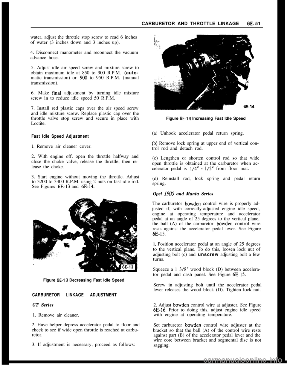
3. Start engine without moving the throttle. Adjust
to 3200 to 3300 R.P.M. using 2 nuts on fast idle rod.
See Figures 6E-13 and
6E-14.Figure
6E-13 Decreasing Fast Idle Speed
CARBURETOR LINKAGE ADJUSTMENT
GT Series1. Remove air cleaner.
2. Have helper depress accelerator pedal to floor and
check to see if wide open throttle is reached at carbu-
retor.
3. If adjustment is necessary, proceed as follows:
6E-14Figure
6E-14 Increasing Fast Idle Speed
(a) Unhook accelerator pedal return spring.
(b) Remove lock spring at upper end of vertical con-
trol rod and detach rod.
(c) Lengthen or shorten control rod so that wide
open throttle is obtained at the carburetor when ac-
celerator pedal is
l/4” - l/2” from floor mat.
(d) Reinstall rod, lock spring and pedal return
spring.
Opel 19W and Manta SeriesThe carburetor bowden control wire is properly ad-
justed if, with correctly-adjusted engine idle speed,
engine at operating temperature and accelerator
pedal at an angle of 25 degrees to the vertical plane,
the ball (A) of the carburetor bowden control wire
rests against the accelerator pedal lever. See Figure
6E-15.
1. Position accelerator pedal at an angle of 25 degrees
to the vertical plane. To do this, loosen lock nut of
adjusting bolt (c) and unscrew adjusting bolt a few
turns.
Squeeze a 1 3/S” wood block (D) between accelera-
tor pedal and dash panel. See Figure
6E-15.Screw in adjusting bolt until the accelerator pedal
lever releases the wood block (D). Tighten lock nut.
2. Adjust bowden control wire at adjuster. See Figure
6E-16. Prior to doing this, adjust engine idle speed
with engine at operating temperature.
Set carburetor bowden control wire adjuster at the
bracket so that the ball (A) of the control wire rests
against part (B) of the accelerator pedal lever and the
wire core between bracket and segmental disc is not
sagging.
Page 343 of 625

6E. 521973 OPEL SERVICE MANUAL
Figure 6E-15 Adjusting Accelerator Cable
Depress accelerator pedal until pedal lever touches
floor mat. The carburetor throttle valve must now be
completely opened.MAJOR REPAIR
REMOVE AND INSTALL CARBURETOR1. Remove air cleaner.
2. Remove fuel and vacuum hoses from carburetor
fittings.
3. Remove choke wire.Figure 6E-16
Bowden Control Wire Adjuster and
Segmental Disc
4. Disconnect throttle linkage by removing lock pin
and unsnapping ball socket from ball on end of throt-
tle shaft.
5. Remove carburetor by removing four nuts and
lockwashers.
Install in reverse order, noting the following:
1. Prior to carburetor insta!lation, place a new gasket
on intake manifold.
2. Make certain that all nuts and screws on the car-
buretor are securely tightened.
3. Make sure that choke housing is set on index and
that choke valve is nearly closed at room tempera-
ture. See Figure
6E-17. Make sure choke valve is free
in all positions.
Figure
LiE-17 Choke Housing Set on Index
Page 346 of 625

CARBURETOR AND THROTTLE LINKAGE6E- 55
float chamber. Clean all parts and blow out with
compressed air. Replace gaskets and seal rings.
14. Check actuating parts in automatic choke body,
including diaphragm, for wear. Check pull rod for
free operation. See Figure 6E-25.15. Remove choke assembly by removing choke
valve and 2 choke housing
- to - carburetor screws.
Figure 6E-25 Checking Automatic Choke Parts
16. Check vacuum case assembly. If bushing is worn,
replace vacuum case assembly. See Figure 6B27.
Figure
6E-27 Checking Vacuum Case Brass Bushings
17. Install secondary vacuum diaphragm case assem-
bly. See Figure 6B28.
18. Install gasket and shield between automatic
choke cover and automatic choke body.Figure
6E-28 Installing Vacuum Case Assembly
19. Install automatic choke cover so that the catch
of the
b&metal spring is positioned onto bent end of
the intermediate lever. See Figure 6B29.
Figure 6G29 Installing Automatic Choke Cover
20. Align and tighten automatic choke cover. Choke
valve should be nearly closed at room temperature.
21. Check vent valve for free operation. Valve rod
must not be bent.
22. Screw in jets according to calibration table.
Never interchange parts of the primary and
second-
xy barrel. See Figure 6E-37.23. Install the throttle body to the bowl, using new
throttle body gasket. Adjust secondary throttle valve
gap by loosening lock nut on the secondary throttle
Page 347 of 625

6E- 561973 OPEL SERVICE MANUAL
valve stop screw. Loosen the stop screw until the
valve is completely closed. Turn the screw in l/4turn from closed position, hold, and tighten lock nut.
This is done to insure that the throttle blade will not
stick closed. See Figure
6E-30.PUMPFigure 6E-30 Adjusting Secondary Throttle Valve Gap
24. Install accelerator pump connecting rod in lower
hole of primary throttle shaft lever and cotter pin in
outboard hole at accelerator pump actuating lever
end. Paying attention to proper arrangement of cot-
ter pin and washers. See Figure
6E-2.25. With throttle plate completely closed, there
should be no clearance between the pump levei and
the pump plunger rod.
26. If a clearance is present, loosen 4 accelerator
Figure
6E-31 Accelerator Pump CoverFigure 6C32 Accelerator Pump Cover
pump cover retaining screws and allow the
dia-’phragm spring to push plunger against lever so that
a zero clearance exists. Then retighten the screws.
See Figures
6E-3 1 and 6E-32.27. Insert accelerator pump discharge nozzle so that
the bent tube end points into suction channel of the
primary barrel.
28. Fill the bowl with fuel.
29. With fuel in bowl, slowly open the throttle and
observe the accelerator pump pressure relief valve
exhaust ports and where it seats into the bowl. See
Figure
6E-33. Fuel should not be bleeding back into
the bowl from the exhaust ports or where the relief
valve seats, but a steady stream of fuel should dis-
charge from the discharge nozzle.
30. With fuel in bowl, rapidly open the throttle atid
observe the exhaust ports of the pressure relief valve.
See Figure
6E-33. Fuel should~exhaust’from the ac-
celerator pump pressure relief valve exhaust ports.
3 1. If the pressure relief valve malfunctions, remove
it and replace with a new one.
32. No float adjustment is possible, so check position
of float arm by comparing with a new float of thesame carburetor type. If float arm is bent, replace
float.
Page 359 of 625
6G- 68 1973 OPEL SERVICE MANUAL
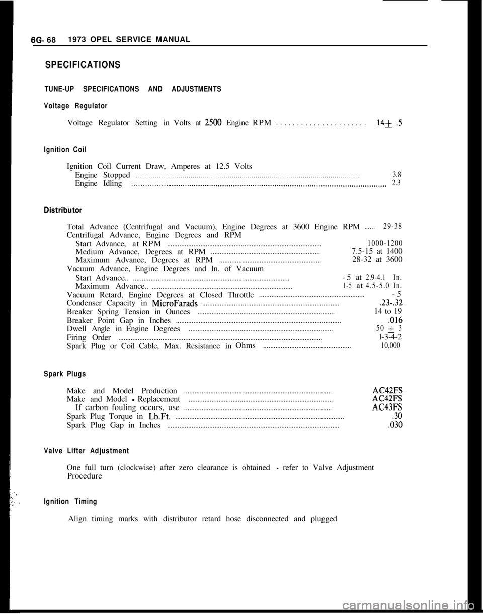
SPECIFICATIONS
TUNE-UP SPECIFICATIONS AND ADJUSTMENTS
Voltage Regulator
Voltage Regulator Setting in Volts at2500 Engine RPM. . . . . . . . . . . . . . . . . . . . . .14+.5
Ignition Coil
Ignition Coil Current Draw, Amperes at 12.5 Volts
Engine Stopped
. . . . . . . . . . . . . . . . . . . . . . . . . . . . . . . . . . . . \
. . . . . . . . . . . . . . . . . . . . . . . . . . . . . . . . . . . . \
. . . . . . . . . . . . . . . . . . . . . . . . . . . . . . . . . . . . \
. . . . . .3.8
EngineIdling. . . . . . . . . . . . . . . . . .._.....................................................................\
........................... 2.3
Total Advance (Centrifugal and Vacuum), Engine Degrees at 3600 Engine \
RPM......29-38
Centrifugal Advance, Engine Degrees and RPM
Start Advance, atRPM
........................................................................\
................ 1000-1200
Medium Advance, Degrees at RPM..............................................................7.5-15 at 1400
Maximum Advance, Degrees at RPM
..........................................................28-32 at 3600
Vacuum Advance, Engine Degrees and In. of Vacuum Start Advance..
........................................................................\
.................-5at2.9-4.1 In.
Maximum Advance..........................................................................\
........1-5at4.5-5.0In.
Vacuum Retard, Engine Degrees at Closed Throttle............................................................-5
Condenser Capacity in
MicroFarads........................................................................\
.......23-.32
Breaker Spring Tension in Ounces........................................................................\
......14 to 19
Breaker Point Gap in Inches
........................................................................\
......................,016
Dwell AngleinEngine Degrees........................................................................\
.......... 50+3
Firing
Order........................................................................\
............................................l-3-4-2
Spark Plug or Coil Cable,Max.Resistance in Ohms
..................................................
10,000
Spark Plugs
Make and Model Production........................................................................\
............AC42FS
Make andModel
-Replacement........................................................................\
..........AC42FS
If carbon fouling occurs, use
........................................................................\
............AC43FS
Spark Plug Torque in
Lb.Ft.........................................................................\
.........................30
Spark Plug Gap in Inches........................................................................\
..........................,030
Valve Lifter Adjustment
One full turn (clockwise) after zero clearance is obtained - refer to Valve Adjustment
Procedure
Ignition Timing
Align timing marks with distributor retard hose disconnected and plugged\
Page 365 of 625
7A- 41973 dPEL SERVICE MANUALConditionPossible CauseCorrectionHeat-blued driven plate
and pressure plate
assembly.
1. Improper pedal1. Replace only driven plate, and
adjustment.adjust clutch pedal and cable.
Grab and chatter with
oil present on clutch
assembly.1. Oil leak.1. Correct oil leakage, clean
pressure plate in solvent, replace
driven plate and adjust pedal lash.
MAINTENANCE AND ADJUSTMENTS
CLUTCH LASH ADJUSTMENT
GTPedal lash, free pedal travel must be adjusted occa-
sionally to compensate for normal wear of the clutch
facings. As the driven plate wears thinner, pedal lash
decreases. Adjust clutch pedal free travel only with
ball stud located on right side of clutch housing if
cable length is not to be changed. To adjust pedal
lash proceed as follows:
1. Loosen lock nut on ball stud end located to the
right of the transmission on the clutch housing. Posi-
tion ball stud so that the outer end protrudes 3/4
inches out of housing and finger tighten lock nut. See
Figures
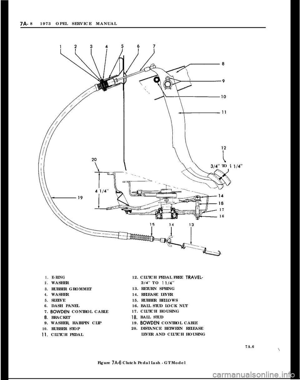
7A-1 and 7A-6.
2. Adjust ball stud, pivoting clutch release fork, to
obtain 3/4 to
l-1/4 inches pedal lash, free pedal. See
Figure 7A-6.
Opel 1900 and MantaThe clutch actuation works without clutch pedal free
travel. A readjustment of the clutch is only required
if the indicator lamp at the instrument panel lights
up.In synchronism with the gradual wear of the clutch
linings the clutch pedal travels from its basic adjust-
ment position upwards,
ie., towards driver. If the
clutch lining wear has reached such an extent that
the clutch pedal rests against switch, the indicator
lamp at the instrument panel lights up.
This is an indication that the clutch pedal position
has to be corrected to ensure proper clutch operat-
ion.
To
&~sure proper clutch operation, observe the fol-
lowing adjustment instructions.. For all adjustment
dimensions, refer to Figure 7A-7.
1. If the parking brake is provided with an indicator
lamp, the parking brake has to be disengaged, other-wise the same indicator lamp as for the clutch lights
UP.2. Carry out adjustment only with ball stud on clutch
housing whereby the distance (Item 20, Figure 7A-7)
between clutch housing contacting surface and
clutch release lever has to be adjusted in the rear to
4
l/4 inches.
Clutch Control Cable Adjustment(Only on
Installation of a New Clutch Disc or
Bowden
Control Wire)
GT1. Adjust ball stud so that outer end protrudes ap-
proximately 3/4 inches out of clutch housing.
2. Adjust distance between release lever and clutch
housing face at eye for control cable to approxi-
mately 4
l/4 inches. See Figure 7A-6. Hold cable in
this position and place E-ring two grooves ahead of
washer on rubber grommet. Clutch pedal free travel
is now between 3/4 and 1
l/4 inches and clutch
release bearing has proper clearance from pressure
plate.
Opel 1900 and Manta1. Adjust ball stud on clutch housing to basic dimen-
sion of approximately 3/4 inch. With lower end ofbowden control wire unhooked, push clutch release
lever towards the front so that the clutch release
bearing rests against clutch spring. Now, adjust ball
stud so that the dimension (Item 20, Figure
7A-7)between clutch housing contacting surface and
clutch release lever amounts in the rear to 4
l/4
inches.2. Pull reattached bowden control wire out of dash
panel so that clutch pedal rests against switch (in-
dicator lamp lights up).
3. In this position, install lockwasher at upper con-
trol wire attachment three grooves towards the front,
thereby completing control wire adjustment.
Page 366 of 625
CLUTCH?A- 5MAJOR REPAIR
CLUTCH REMOVAL AND INSTALLATION
Remove Clutch1. Remove transmission. Refer to Manual Transmis-
sion for removal procedure.
2. Remove bolts from engine support brackets, both
sides. Let brackets hang by front bolts.
3. Remove flywheel cover pan.
4. Remove flywheel housing to engine attaching
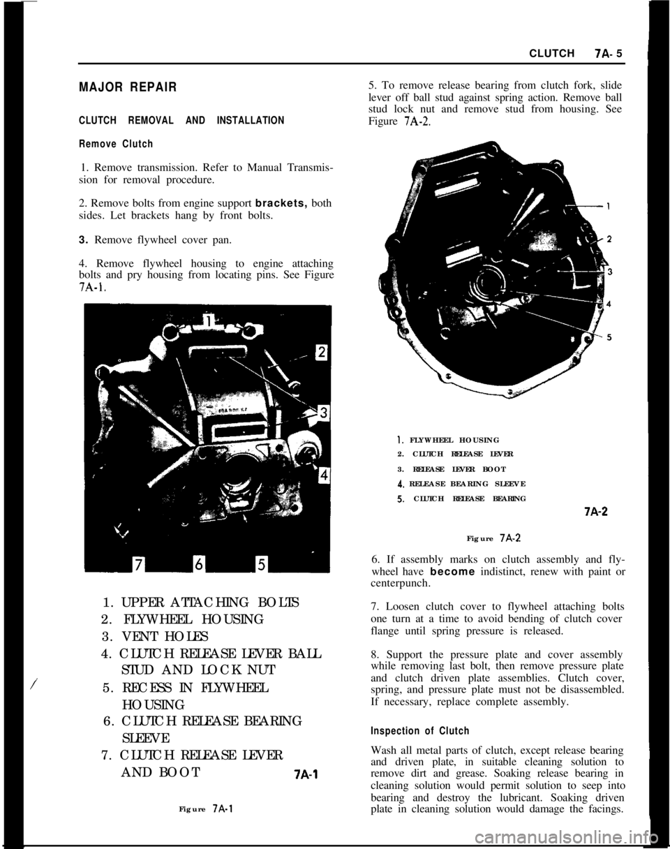
bolts and pry housing from locating pins. See Figure7A-1.
/1. UPPER ATTACHING BOLTS
2. FLYWHEEL HOUSING
3. VENT HOLES
4. CLUTCH RELEASE LEVER BALL
STUD AND LOCK NUT
5. RECESS IN FLYWHEEL
HOUSING
6. CLUTCH RELEASE BEARING
SLEEVE
7. CLUTCH RELEASE LEVER
AND BOOT
7A-1Figure 7A-15. To remove release bearing from clutch fork, slide
lever off ball stud against spring action. Remove ball
stud lock nut and remove stud from housing. See
Figure
7A-2.
1. FLYWHEEL HOUSING
2. CLUTCH RELEASE LEVER
3. RELEASE LEVER BOOT
4. RELEASE BEARING SLEEVES. CLUTCH RELEASE BEARINGi-A-2
Figure 7A-2
6. If assembly marks on clutch assembly and fly-
wheel have become indistinct, renew with paint or
centerpunch.
7. Loosen clutch cover to flywheel attaching bolts
one turn at a time to avoid bending of clutch cover
flange until spring pressure is released.
8. Support the pressure plate and cover assembly
while removing last bolt, then remove pressure plate
and clutch driven plate assemblies. Clutch cover,
spring, and pressure plate must not be disassembled.
If necessary, replace complete assembly.
Inspection of ClutchWash all metal parts of clutch, except release bearing
and driven plate, in suitable cleaning solution to
remove dirt and grease. Soaking release bearing in
cleaning solution would permit solution to seep into
bearing and destroy the lubricant. Soaking driven
plate in cleaning solution would damage the facings.
Page 369 of 625
7A- 81973 OPEL SERVICE MANUAL\\“\314”TO ,l
17
16
1.E-RING12. CLUTCH PEDAL FREE TRAVEL-
2.WASHER3/4” TO 1 l/4”
3.RUBBER GROMMET13. RETURN SPRING
4.WASHER14. RELEASE LEVER
5.SLEEVE15. RUBBER BELLOWS
6.DASH PANEL16. BALL STUD LOCK NUT
7. BOWDEN CONTROL CABLE17. CLUTCH HOUSING
8.BRACKET18. BALL STUD
9. WASHER, HAIRPIN CLIP19. BOWDEN CONTROL CABLE
10.RUBBER STOP20. DISTANCE BETWEEN RELEASE
11.CLUTCH PEDALLEVER AND CLUTCH HOUSING
7A.6\
Figure
7A-6 Clutch Pedal Lash - GT Model