lock OPEL GT-R 1973 Service Manual
[x] Cancel search | Manufacturer: OPEL, Model Year: 1973, Model line: GT-R, Model: OPEL GT-R 1973Pages: 625, PDF Size: 17.22 MB
Page 286 of 625
DRUM BRAKES5C- 27MAINTENANCE AND ADJUSTMENTSBRAKE ADJUSTMENT
Preliminary Checks
1. Depress brake pedal firmly. If pedal travels to
within two inches of toeboard and has a hard feel,
brake shoes require adjustment or relining. However,
if pedal has a spongy feel, brake system needs bleed-
ing.2. Remove one rear drum if lining is worn nearly to
rivets. Reline both rear brakes (drum brakes only).
3. Check fluid level in master cylinder reservoir and
add fluid if necessary.
4. Fully release parking brake lever and place trans-
mission in neutral.
5. Pull on both ends of rear brake cable a number of
times to make sure that cables operate rear brake
shoes freely and do not bind in conduits. Check for
free movement of cable in brake cable sheave and
check brake cable spring for tension. Replace a weak
or broken cable spring.
Pedal Height Adjustment
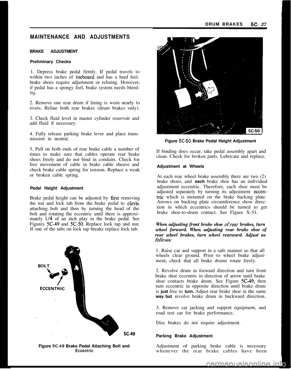
Brake pedal height can be adjusted by first removing
the nut and lock tab from the brake pedal to clevis
attaching bolt and then by turning the head of the
bolt and rotating the eccentric until there is approxi-
mately
l/4 of an inch play in the brake pedal. See
Figures
X-49 and 5C-50. Replace lock tap and nut.
If one of the tabs on lock tap breaks replace lock tab.5c49
Figure 5C-49 Brake Pedal Attaching Bolt and
EccentricFigure 5C-50 Brake Pedal Height Adjustment
If binding does occur, take pedal assembly apart and
clean. Check for broken parts. Lubricate and replace.
Adjustment at Wheels
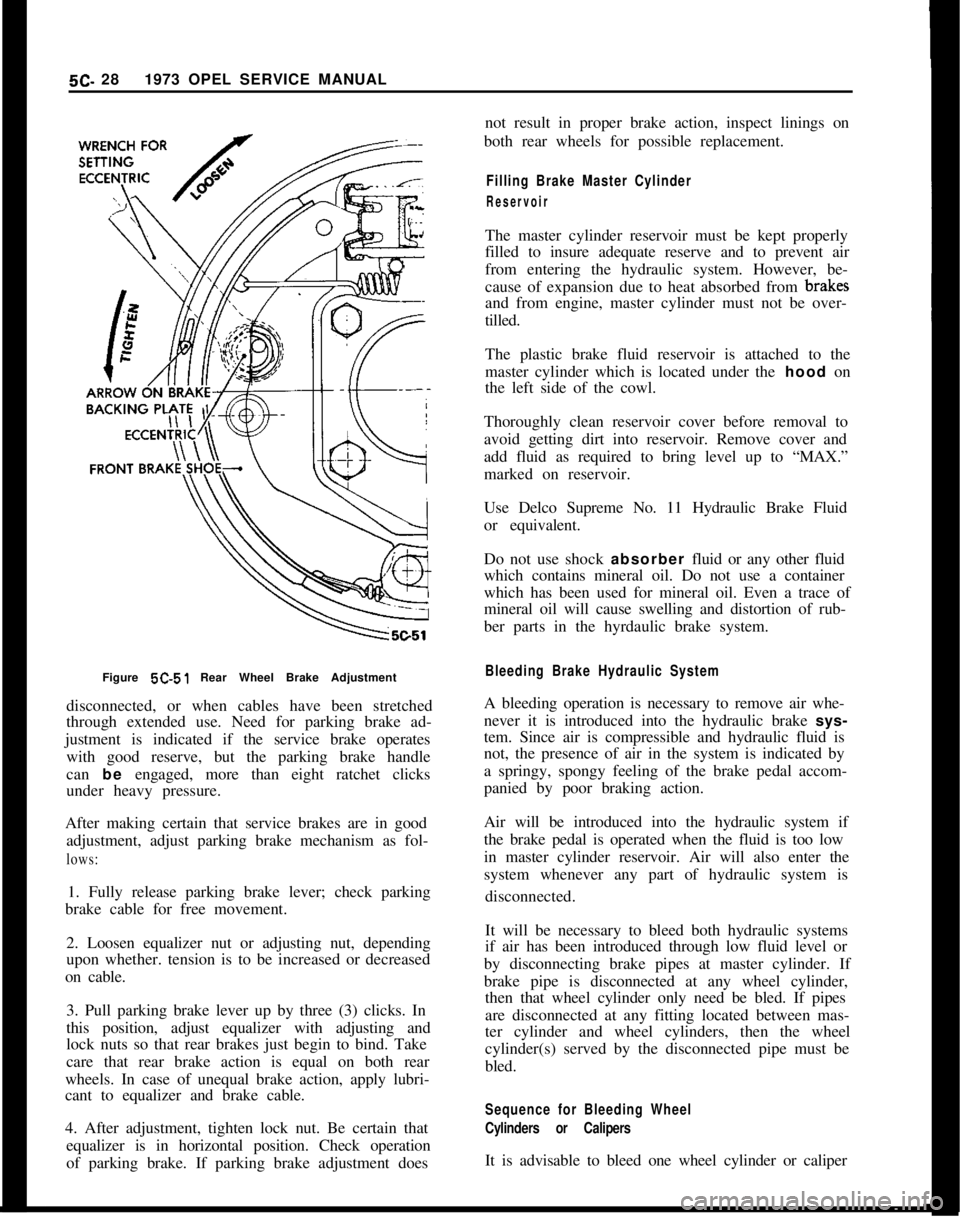
At each rear wheel brake assembly there are two (2)
brake shoes, and each brake shoe has an individual
adjustment eccentric. Therefore, each shoe must be
adjusted separately by turning its adjustment
ccccn-tric which is mounted on the brake backing plate.
Arrows on backing plate circumference show direc-
tion in which eccentrics should be turned to get
brake shoe-to-drum contact. See Figure X-51.
When adjusting front brake shoe ofrear brakes, turn
wheel forward. When adjusting rear brake shoe of
rear wheel brakes, turn wheel rearward. Adjust as
folio ws:1. Raise car and support in a safe manner so that all
wheels clear ground. Prior to wheel brake adjust-
ment, check that all brake drums rotate freely.
2. Revolve drum in forward direction and turn front
brake shoe eccentric in direction of arrow until brake
shoe contacts brake drum. See Figure
5C-49, then
turn eccentric in opposite direction until brake drum
is just free to turn. Adjust rear brake shoe in the same
way but revolve brake drum in backward direction.
3. Remove car jacking and support equipment, and
road test car for brake performance.
Disc brakes do not require adjustment.
Parking Brake Adjustment
Adjustment of parking brake cable is necessary
whenever the rear brake cables have been
Page 287 of 625
5C- 281973 OPEL SERVICE MANUAL
Figure 5C-51 Rear Wheel Brake Adjustment
disconnected, or when cables have been stretched
through extended use. Need for parking brake ad-
justment is indicated if the service brake operates
with good reserve, but the parking brake handle
can be engaged, more than eight ratchet clicks
under heavy pressure.
After making certain that service brakes are in good
adjustment, adjust parking brake mechanism as fol-lows:1. Fully release parking brake lever; check parking
brake cable for free movement.
2. Loosen equalizer nut or adjusting nut, depending
upon whether. tension is to be increased or decreased
on cable.
3. Pull parking brake lever up by three (3) clicks. In
this position, adjust equalizer with adjusting and
lock nuts so that rear brakes just begin to bind. Take
care that rear brake action is equal on both rear
wheels. In case of unequal brake action, apply lubri-
cant to equalizer and brake cable.
4. After adjustment, tighten lock nut. Be certain that
equalizer is in horizontal position. Check operation
of parking brake. If parking brake adjustment doesnot result in proper brake action, inspect linings on
both rear wheels for possible replacement.
Filling Brake Master Cylinder
ReservoirThe master cylinder reservoir must be kept properly
filled to insure adequate reserve and to prevent air
from entering the hydraulic system. However, be-
cause of expansion due to heat absorbed from brakff
and from engine, master cylinder must not be over-
tilled.
The plastic brake fluid reservoir is attached to the
master cylinder which is located under the hood on
the left side of the cowl.
Thoroughly clean reservoir cover before removal to
avoid getting dirt into reservoir. Remove cover and
add fluid as required to bring level up to “MAX.”
marked on reservoir.
Use Delco Supreme No. 11 Hydraulic Brake Fluid
or equivalent.
Do not use shock absorber fluid or any other fluid
which contains mineral oil. Do not use a container
which has been used for mineral oil. Even a trace of
mineral oil will cause swelling and distortion of rub-
ber parts in the hyrdaulic brake system.
Bleeding Brake Hydraulic SystemA bleeding operation is necessary to remove air whe-
never it is introduced into the hydraulic brake sys-
tem. Since air is compressible and hydraulic fluid is
not, the presence of air in the system is indicated by
a springy, spongy feeling of the brake pedal accom-
panied by poor braking action.
Air will be introduced into the hydraulic system if
the brake pedal is operated when the fluid is too low
in master cylinder reservoir. Air will also enter the
system whenever any part of hydraulic system is
disconnected.
It will be necessary to bleed both hydraulic systems
if air has been introduced through low fluid level or
by disconnecting brake pipes at master cylinder. If
brake pipe is disconnected at any wheel cylinder,
then that wheel cylinder only need be bled. If pipes
are disconnected at any fitting located between mas-
ter cylinder and wheel cylinders, then the wheel
cylinder(s) served by the disconnected pipe must be
bled.
Sequence for Bleeding Wheel
Cylinders or CalipersIt is advisable to bleed one wheel cylinder or caliper
Page 294 of 625
ENGINE MECHANICAL AND MOUNTS6A- 3
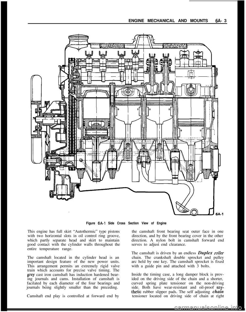
Figure 6A-1 Side Cross Section View of Engine
This engine has full skirt “Autothermic” type pistons
with two horizontal slots in oil control ring groove,
which partly separate head and skirt to maintain
good contact with the cylinder walls throughout the
entire temperature range.
The camshaft located in the cylinder head is an
important design feature of the new power units.
This arrangement permits an extremely rigid valve
train which accounts for precise valve timing. Thegray cast iron camshaft has induction hardened bear-
ing journals and cams. Installation of camshaft is
facilated by each diameter of the four bearings and
journals being slightly smaller than the preceding.
Camshaft end play is controlled at forward end bythe camshaft front bearing seat outer face in one
direction, and by the front bearing cover in the other
direction. A nylon bolt in camshaft forward end
serves to adjust end clearance.
The camshaft is driven by an endless Duplex
rollerchain. The crankshaft double sprocket and pulley
arc held by one key. The camshaft sprocket is fixed
with a guide pin and attached with 3 bolts.
Inside the timing case, a long damper block is prov-
ided on the driving side of the chain and a shorter,
curved spring plate tensioner on the non-driving
side. Both have wear-resistant and oil-proof
sny-thetic rubber slipper pads. The self adjusting chain
tensioner located on driving side of chain at right
Page 295 of 625
6A. 41973 OPEL SERVICE MANUAL
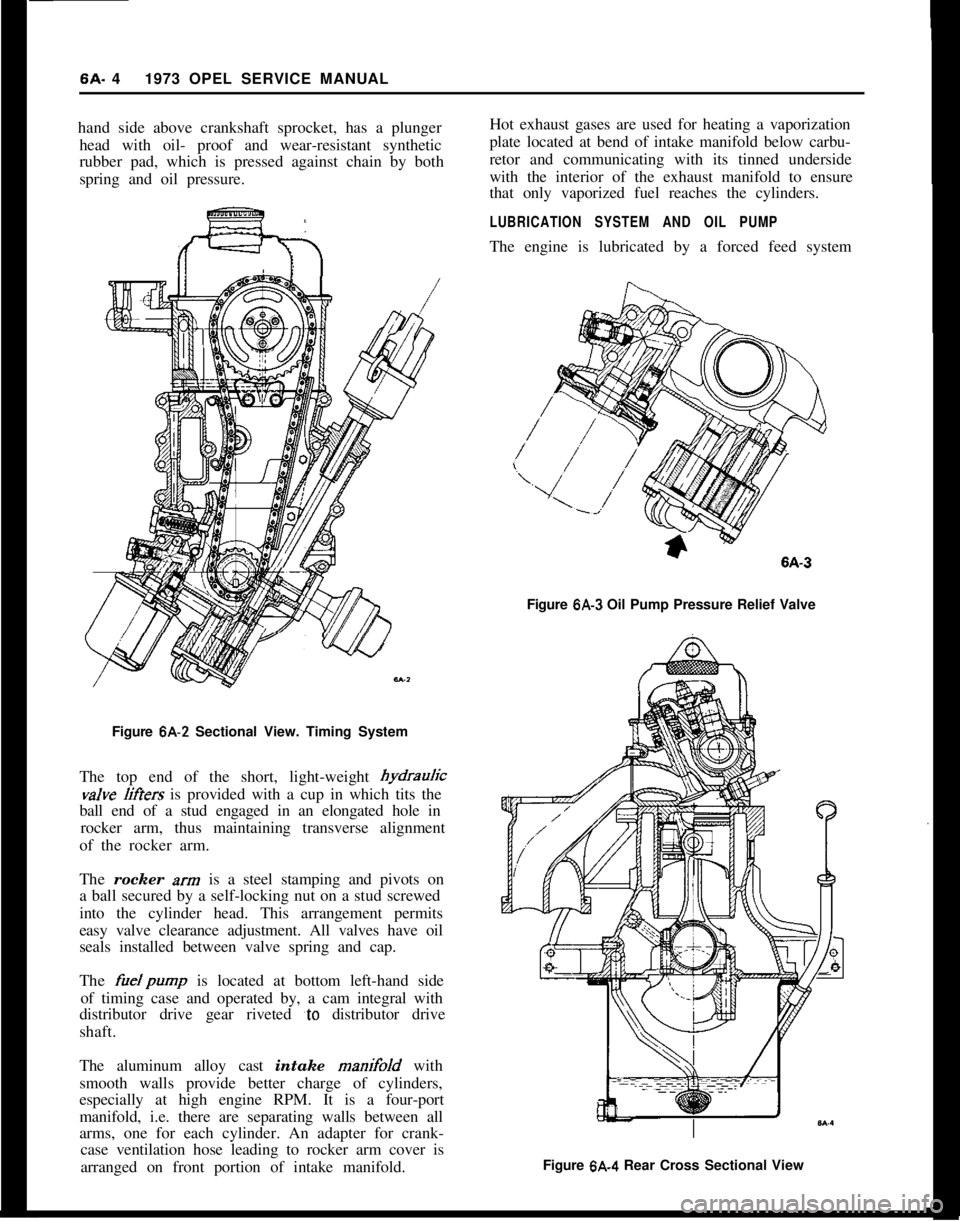
hand side above crankshaft sprocket, has a plunger
head with oil- proof and wear-resistant synthetic
rubber pad, which is pressed against chain by both
spring and oil pressure.
Figure 6A-2 Sectional View. Timing System
The top end of the short, light-weight hydrauricvalve
liffers is provided with a cup in which tits the
ball end of a stud engaged in an elongated hole in
rocker arm, thus maintaining transverse alignment
of the rocker arm.
The rocker
xrn is a steel stamping and pivots on
a ball secured by a self-locking nut on a stud screwed
into the cylinder head. This arrangement permits
easy valve clearance adjustment. All valves have oil
seals installed between valve spring and cap.
The
fuelpump is located at bottom left-hand side
of timing case and operated by, a cam integral with
distributor drive gear riveted
‘to distributor drive
shaft.
The aluminum alloy cast intake manifold with
smooth walls provide better charge of cylinders,
especially at high engine RPM. It is a four-port
manifold, i.e. there are separating walls between all
arms, one for each cylinder. An adapter for crank-
case ventilation hose leading to rocker arm cover is
arranged on front portion of intake manifold.Hot exhaust gases are used for heating a vaporization
plate located at bend of intake manifold below carbu-
retor and communicating with its tinned underside
with the interior of the exhaust manifold to ensure
that only vaporized fuel reaches the cylinders.
LUBRICATION SYSTEM AND OIL PUMPThe engine is lubricated by a forced feed system
Figure
6A-3 Oil Pump Pressure Relief Valve
Figure 6A.4 Rear Cross Sectional View
Page 296 of 625
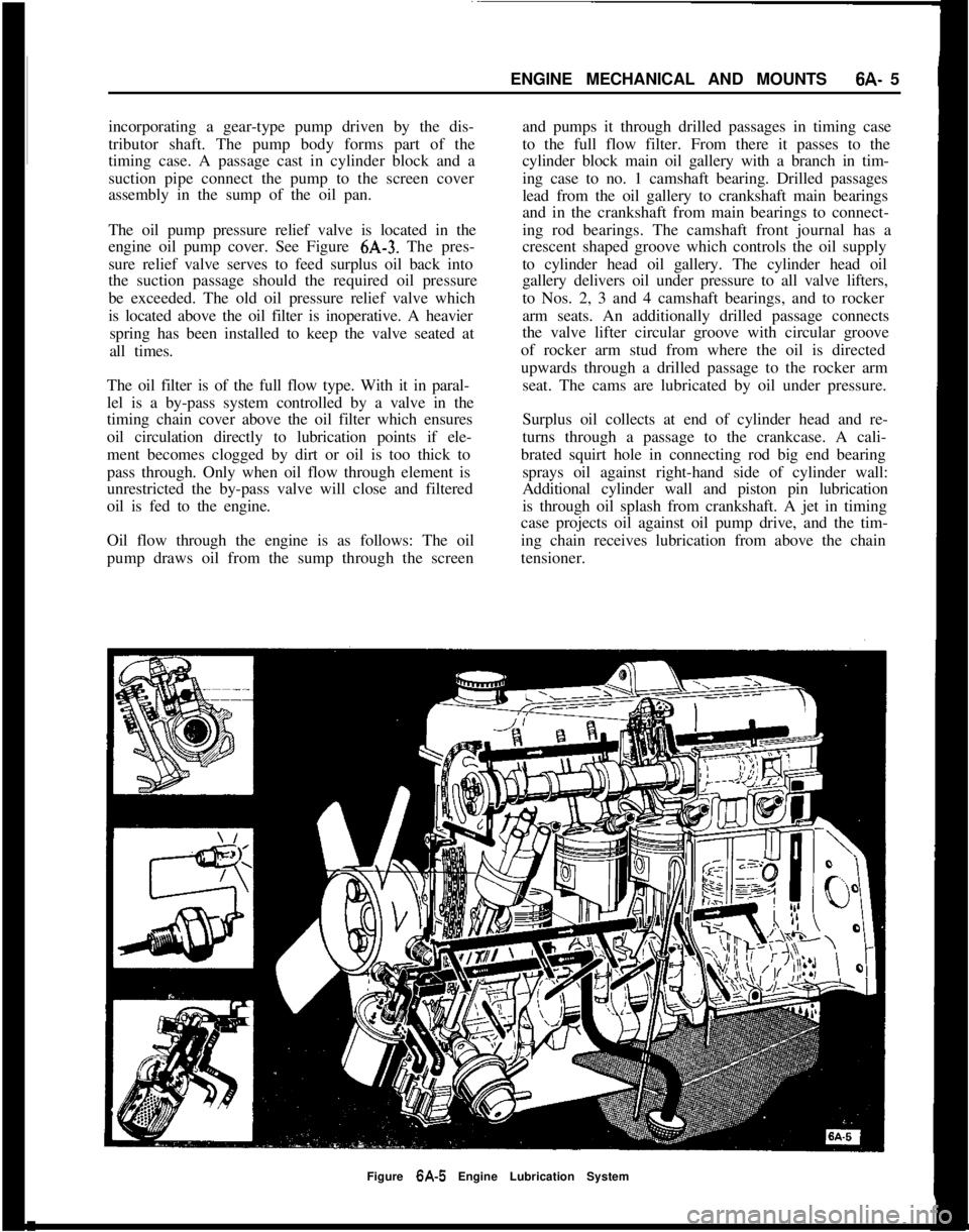
ENGINE MECHANICAL AND MOUNTS6A- 5
incorporating a gear-type pump driven by the dis-
tributor shaft. The pump body forms part of the
timing case. A passage cast in cylinder block and a
suction pipe connect the pump to the screen cover
assembly in the sump of the oil pan.
The oil pump pressure relief valve is located in the
engine oil pump cover. See Figure 6A-3. The pres-
sure relief valve serves to feed surplus oil back into
the suction passage should the required oil pressure
be exceeded. The old oil pressure relief valve which
is located above the oil filter is inoperative. A heavier
spring has been installed to keep the valve seated at
all times.
The oil filter is of the full flow type. With it in paral-
lel is a by-pass system controlled by a valve in the
timing chain cover above the oil filter which ensures
oil circulation directly to lubrication points if ele-
ment becomes clogged by dirt or oil is too thick to
pass through. Only when oil flow through element is
unrestricted the by-pass valve will close and filtered
oil is fed to the engine.
Oil flow through the engine is as follows: The oil
pump draws oil from the sump through the screenand pumps it through drilled passages in timing case
to the full flow filter. From there it passes to the
cylinder block main oil gallery with a branch in tim-
ing case to no. 1 camshaft bearing. Drilled passages
lead from the oil gallery to crankshaft main bearings
and in the crankshaft from main bearings to connect-
ing rod bearings. The camshaft front journal has a
crescent shaped groove which controls the oil supply
to cylinder head oil gallery. The cylinder head oil
gallery delivers oil under pressure to all valve lifters,
to Nos. 2, 3 and 4 camshaft bearings, and to rocker
arm seats. An additionally drilled passage connects
the valve lifter circular groove with circular groove
of rocker arm stud from where the oil is directed
upwards through a drilled passage to the rocker arm
seat. The cams are lubricated by oil under pressure.
Surplus oil collects at end of cylinder head and re-
turns through a passage to the crankcase. A cali-
brated squirt hole in connecting rod big end bearing
sprays oil against right-hand side of cylinder wall:
Additional cylinder wall and piston pin lubrication
is through oil splash from crankshaft. A jet in timing
case projects oil against oil pump drive, and the tim-
ing chain receives lubrication from above the chain
tensioner.
Figure 6A-5 Engine Lubrication System
Page 299 of 625
6A- 8 1973 OPEL SERVICE MANUAL
Actual adjustment is made by backing off adjusting
nut at the rocker arm until clearance exists between the valve stem, rocker arm, and lifter. Then slowly
tighten adjusting nut until clearance is eliminated.
When clearance is eliminated, turn adjusting nut one
full turn (clockwise). This positions the hydraulic
piston of the hydraulic lifter mid-point in its total
available travel, and no further adjustment is re-
quired.
MAJOR REPAIR
ENGINE ASSEMBLY REMOVAL AND
INSTALLATION
Removal (Opel 1900 and Manta)’
The engine assembly on the Opel 1900 and Manta
can be removed together with the transmission
through the top of the engine compartment.
1. Remove hood (scribe hood hinge to hood mount-
ing location).
2. Disconnect battery negative cable.
3. Drain coolant at lower radiator hose.
4. Remove upper and lower radiator hoses.
5. Remove radiator and fan
shrbud.
6. Disconnect heater hoses.
7. Disconnect brake booster
vacuum hose.
8. Remove air cleaner.
9. Disconnect electrical connections and accelerator
linkage. 10. Remove console.
11. Remove shift lever boot, plate, and shift lever.
12. Raise car on hoist.
13. Disconnect fuel line at pump.
14. Remove front stone shield.
15. Disconnect speedo-cable, back-up light switch,
and clutch cable.
16. Remove drive shaft. I
17. Disconnect exhaust pipe
ar$l bell housing sup-
port.
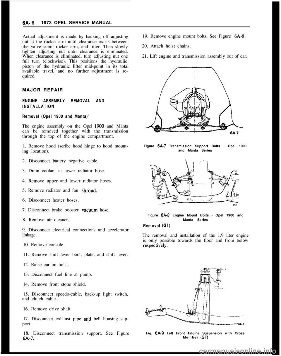
18. Disconnect transmission support. See Figure
6A-7. 19. Remove engine mount bolts. See Figure
6A-8.
20. Attach hoist chains.
21. Lift engine and transmission assembly out of car.
Figure 6A-7 Transmission Support Bolts . Opel 1900
and Manta Series
Figure
6A-B Engine Mount Bolts - Opel 1900 and
Manta Series
Removal (GT)
The removal and installation of the 1.9 liter engine is only possible towards the floor and from below
Fig, 6A-9 Left Front Engine Suspension with Cross
Member (GT)
Page 300 of 625
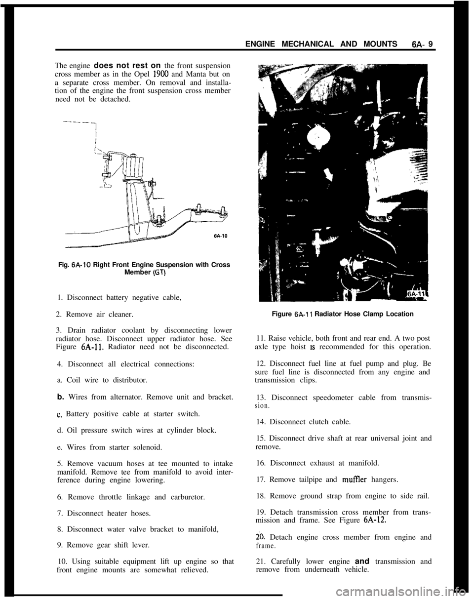
ENGINE MECHANICAL AND MOUNTS6A- 9
The engine does not rest on the front suspension
cross member as in the Opel 1900 and Manta but on
a separate cross member. On removal and installa-
tion of the engine the front suspension cross member
need not be detached.
Fig. 6A-10 Right Front Engine Suspension with Cross
Member
(GT)1. Disconnect battery negative cable,
2. Remove air cleaner.
3. Drain radiator coolant by disconnecting lower
radiator hose. Disconnect upper radiator hose. See
Figure 6A-11. Radiator need not be disconnected.
4. Disconnect all electrical connections:
a. Coil wire to distributor.
b. Wires from alternator. Remove unit and bracket.
c. Battery positive cable at starter switch.
d. Oil pressure switch wires at cylinder block.
e. Wires from starter solenoid.
5. Remove vacuum hoses at tee mounted to intake
manifold. Remove tee from manifold to avoid inter-
ference during engine lowering.
6. Remove throttle linkage and carburetor.
7. Disconnect heater hoses.
8. Disconnect water valve bracket to manifold,
9. Remove gear shift lever.
10. Using suitable equipment lift up engine so that
front engine mounts are somewhat relieved.Figure 6A.1
1 Radiator Hose Clamp Location
11. Raise vehicle, both front and rear end. A two post
axle type hoist
IS recommended for this operation.
12. Disconnect fuel line at fuel pump and plug. Be
sure fuel line is disconnected from any engine and
transmission clips.
13. Disconnect speedometer cable from transmis-
sion.14. Disconnect clutch cable.
15. Disconnect drive shaft at rear universal joint and
remove.
16. Disconnect exhaust at manifold.
17. Remove tailpipe and mufIler hangers.
18. Remove ground strap from engine to side rail.
19. Detach transmission cross member from trans-
mission and frame. See Figure 6A-12.
20. Detach engine cross member from engine and
frame.21. Carefully lower engine and transmission and
remove from underneath vehicle.
Page 302 of 625
ENGINE MECHANICAL AND MOUNTS6A- 11
a. Attach left chain to alternator support rear bolt.
b. Bolt right chain to existing threaded hole at lower
right front of engine.
2. Assemble loose ends of chain to support device J-bolts and adjust to remove engine weight from motor
mounts.
3. Remove the two motor mount bracket to motor
mount retaining nuts.
4. Remove the two front suspension to frame rail bolt
retaining nuts.
5. Remove nut and bolt at lower end of steering shaft
U-joint.
6. With a floor jack under the center of the front
suspension cross member, raise car high enough for
wheels and suspension assembly to be rolled from
under car.
7. Position jack stands under both front jack brackets
on underbody to support car in this position.
8. Remove both front cross member support to frame
attaching bolts.
9. Remove brake pipe to brake hose retaining clips
at frame rails and disconnect brake hose from brake
pipes. Use an absorbent material or suitable con-
tainer for the brake fluid that will drain out.
10. Lower the front suspension assembly and remove
from under car.
11. Drain engine oil and remove oil pan and gasket.
Installation (Opel 1900 and Manta)1. Apply a light bead of sealer to the clean sealing
surfaces of the oil pan and affix a new gasket.
2. Bolt oil pan and gasket assembly to engine block.
3. Roll front suspension and floor jack under car and
raise into position careful to pilot the cross member
to frame rail attaching bolts and steering shaft to
their respective locations.
4. Install cross member’support to frame attaching
bolts and torque to 22 lb.ft.
5. Connect brake hose to brake pipes and install
retaining clips.
6. Bleed front brake system. Maintain brake fluid1Wd.
7. Remove jack stands and lower car.8. Install suspension to frame rail bolt retaining nuts.
9. Release and remove engine supporting device.
10. Install motor mount bracket to motor mount
retaining nuts.
11. Install steering shaft U-joint lower bolt and nut.
12. Replace engine oil.
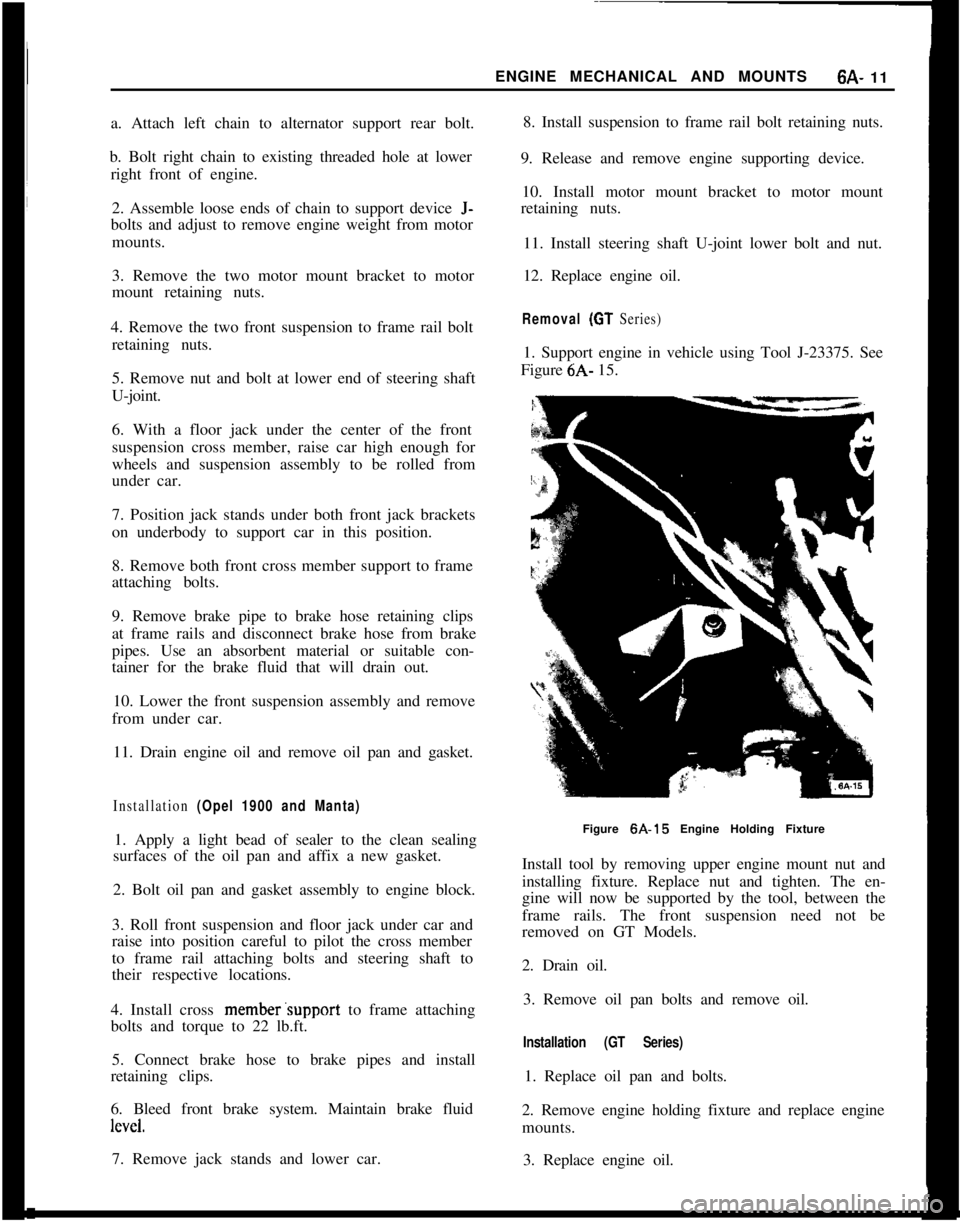
Removal (GT Series)1. Support engine in vehicle using Tool J-23375. See
Figure 6A- 15.
Figure 6A-15 Engine Holding Fixture
Install tool by removing upper engine mount nut and
installing fixture. Replace nut and tighten. The en-
gine will now be supported by the tool, between the
frame rails. The front suspension need not be
removed on GT Models.
2. Drain oil.
3. Remove oil pan bolts and remove oil.
Installation (GT Series)1. Replace oil pan and bolts.
2. Remove engine holding fixture and replace engine
mounts.
3. Replace engine oil.
Page 303 of 625
6A- 121973 OPEL SERVICE MANUALINTAKE AND EXHAUST MANIFOLD REMOVAL
AND
INSTALLATION
Removal1. Disconnect battery.
2. Remove air cleaner.
3. Disconnect throttle linkage at carburetor.
4. Disconnect vacuum advance line at carburetor.
5. Remove fuel line at carburetor inlet.
6. Remove positive crankcase ventilation hose at
rocker arm cover.
7. Disconnect E.G.R. lines from carburetor and in-
take manifold.
8. Disconnect exhaust pipe.
9. Remove six bolts attaching manifold assembly to
cylinder head and remove manifold and carburetor
as an assembly. Discard manifold gasket.
To separate intake and exhaust, manifold, remove
carburetor and four bolts using Tool J-23016, attach-
ing intake manifold to exhaust manifold. Always in-
stall a new manifold intermediate gasket when the
manifolds are separated.
Installation1. Install new manifold gasket and place manifold in
position.
2. Install manifold bolts. New manifold to cylinder
head gasket must be installed whenever a manifold
is removed.
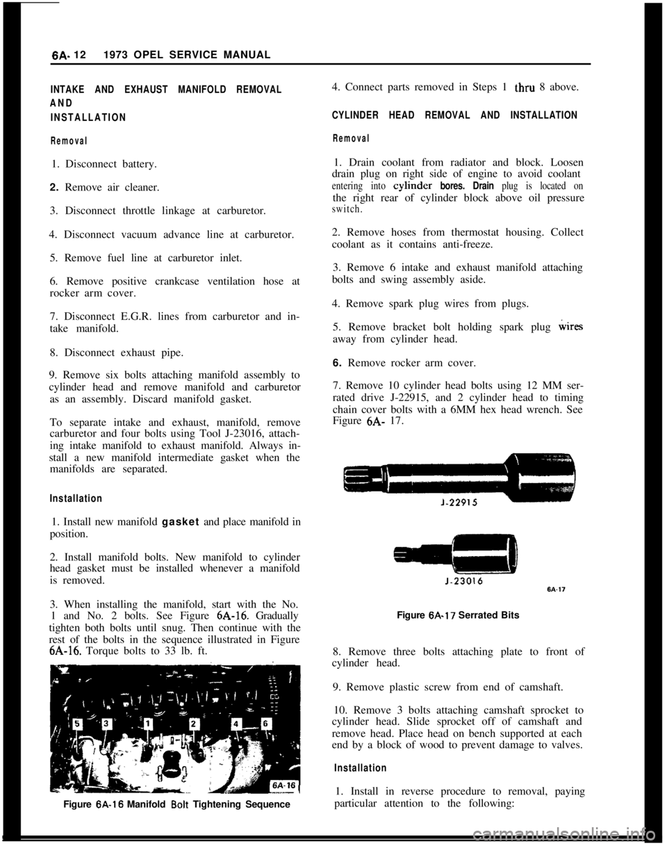
3. When installing the manifold, start with the No.
1 and No. 2 bolts. See Figure 6A-16. Gradually
tighten both bolts until snug. Then continue with the
rest of the bolts in the sequence illustrated in Figure6A-16. Torque bolts to 33 lb. ft.
Figure 6A-16 Manifold
Bolt Tightening Sequence4. Connect parts removed in Steps 1 thru 8 above.
CYLINDER HEAD REMOVAL AND INSTALLATION
Removal1. Drain coolant from radiator and block. Loosen
drain plug on right side of engine to avoid coolant
entering into cylmder bores. Drain plug is located onthe right rear of cylinder block above oil pressure
switch.2. Remove hoses from thermostat housing. Collect
coolant as it contains anti-freeze.
3. Remove 6 intake and exhaust manifold attaching
bolts and swing assembly aside.
4. Remove spark plug wires from plugs.
5. Remove bracket bolt holding spark plug wires
away from cylinder head.
6. Remove rocker arm cover.
7. Remove 10 cylinder head bolts using 12 MM ser-
rated drive J-22915, and 2 cylinder head to timing
chain cover bolts with a 6MM hex head wrench. See
Figure 6A- 17.
Figure 6A-17 Serrated Bits
8. Remove three bolts attaching plate to front of
cylinder head.
9. Remove plastic screw from end of camshaft.
10. Remove 3 bolts attaching camshaft sprocket to
cylinder head. Slide sprocket off of camshaft and
remove head. Place head on bench supported at each
end by a block of wood to prevent damage to valves.
Installation1. Install in reverse procedure to removal, paying
particular attention to the following:
Page 304 of 625
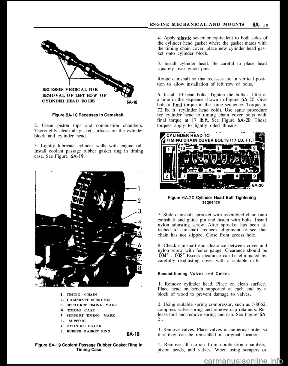
RECESSES VERTICAL FOR
REMOVAL OF LEFT ROW OF
CYLINDER HEAD BOLTS6A-16
Figure 6A-18 Recesses in Camshaft
2. Clean piston tops and combustion chambers.
Thoroughly clean all gasket surfaces on the cylinder
block and cylinder head.
3. Lightly lubricate cylinder walls with engine oil.
Install coolant passage rubber gasket ring in timing
case. See Figure 6A-19.I. TIMING CHAIN
2. CAMSHAFT SPROCKET
3. SPROCKET TIMING MARK
4. TIMING CASE5. SUPPORT TIMING MARK
6. SUPPORT
7. CYLINDER BLOCK
6. RUBBER GASKET RING6A-19
Figure 6A-19 Coolant Passage Rubber Gasket Ring in
Timing CaseENGINE MECHANICAL AND MOUNTS
6A- 13
4. Apply silastic sealer or equivalent to both sides of
the cylinder head gasket where the gasket mates with
the timing chain cover, place new cylinder head gas-
ket onto cylinder block.
5. Install cylinder head. Be careful to place head
squarely over guide pins.
Rotate camshaft so that recesses are in vertical posi-
tion to allow installation of left row of bolts.
6. Install 10 head bolts. Tighten the bolts a little at
a time in the sequence shown in Figure 6A-20. Give
bolts a final torque in the same sequence. Torque to
72 lb. ft. (cylinder head cold). Use same procedure
for cylinder head to timing chain cover bolts with
final torque at 17
lb.ft. See Figure 6A-20. These
torques apply to lightly oiled threads.
Figure 6A-20 Cylinder Head Bolt Tightening
sequence7. Slide camshaft sprocket with assembled chain onto
camshaft and guide pin and fasten with bolts. Install
nylon adjusting screw. After sprocket has been at-
tached to camshaft, recheck alignment to see that
chain has not slipped. Close front access hole.
8. Check camshaft end clearance between cover and
nylon screw with feeler gauge. Clearance should be
.004” - .008” Excess clearance can be eliminated by
carefully readjusting cover with a suitable drift.
Reconditioning Valves and Guides1. Remove cylinder head. Place on clean surface.
Place head on bench supported at each end by a
block of wood to prevent damage to valves.
2. Using suitable spring compressor, such as J-8062,
compress valve spring and remove cap retainers. Re-
lease tool and remove spring and cap. See Figure 6A-
21.3. Remove valves. Place valves in numerical order so
that they can be reinstalled in original location.
4. Remove all carbon from combustion chambers,
piston heads, and valves. When using scrapers or