ESP inoperative OPEL GT-R 1973 Service Manual
[x] Cancel search | Manufacturer: OPEL, Model Year: 1973, Model line: GT-R, Model: OPEL GT-R 1973Pages: 625, PDF Size: 17.22 MB
Page 228 of 625

WHEELS AND TIRES3G- 61Cornering Tread WearThe modern independently-sprung automobile al-
lows the driver to negotiate turns at a high rate of
speed with a greater feeling of safety. This fact is
responsible for a comparatively new type of tread
wear that can easily be mistaken for toe or camber
wear.When a car is making a turn, the tires are supposed
to be rolling in a circle. When the turn is made at
high speed, however, centrifugal force acting on the
car causes the tires to be distorted sideways and to
slip or skid on the road surface. This produces a
diagonal cross type of wear, which in severe cases
will result in a fine or sharp edge on each rib of the
tire treads.
Cornering wear can be distinguished from toe or
camber wear by the rounding of the outside shoulder
of the tire and by the roughening of tread surface in
this section denoting severe abrasion. See Figure
3G-7.No alignment or tire pressure cahnge can be made
that will relieve cornering wear. Only the driver can
effect a cure and that is by slowing down on curves.
Heel and Toe Tread WearHeel and toe wear is a saw-tooth effect with one end
of each tread block worn more than the other.
The end which wears is the one that first grips the
road when the brakes are applied. High-speed driv-
ing and excessive “se of the brakes will cause this
type of irregular tire wear. This type of wear will
occur on any type of block tread design. See Figure3G-7.
Heel and toe wear is not so prevalent on the rear tires
because of the propelling action which creates a
counteracting force which wears the opposite end of
the tread block. These two stresses on the rear tires
wear the tread blocks in opposite directions and re-
sult in more even wear while on the front tires, the
braking stress is the only one which is effective. This
may be counteracted by interchanging tires.
A small amount of irregular wear, slightly
saw-toothed in appearance, at the outer segments of tires
is a normal condition and is due to the difference in
circumference between the center and the outer
edges of the tire tread. This saw-toothed appearance,
however, will be exaggerated by underinflation, im-
proper toe-in, or both.Cupped or Scalloped Type Tire Wear
Cupping or scalloping is associated with wear on acar driven mostly at highway speeds without recom-
mended tire rotation. Factors which promote cup-
ping include underinflation, incorrect toe-in setting
or camber setting, and steady highway speeds on
smooth, paved surfaces as opposed to gravel or
rough asphalt.
The following recommendations suggest action that
may be taken to help prevent cupping.
1. Rotate tires as recommended in Figure
3G-6.2. Frequently inspect front tires for irregular wear
due to underinflation, improper toe-in setting, or
camber setting. Regardless of the original cause of
cupped tread wear on either front tire, no alignment
or balance job, however perfect, can prevent future
excessive wear of the spots. Once a front tire acquires
flat or cupped spots, additional wear will continue at
a rapid rate. At the time of correction, however, the
cupped tire should be interchanged with a rear tire
on which the tread runs true. The cupped tire will,
to a certain degree, true itself on a rear wheel.
Although not normally the cause of cupping, the
following factors can contribute to the problem.
Looseness of parts in the suspension system, such as
worn steering knuckle ball joints, loose wheel bear-
ings, inoperative shock absorbers, and any excessive
looseness throughout the steering system all tend to
allow the front wheels to kick around and, if any of
the wheel alignment factors are incorrect, irregular
spotty tire tread wear of one type or another may
result.
Wobble or runout of a tire, either front or rear, due
to bent wheel or to tire being improperly mounted
will cause uneven wear.
MAINTENANCE AND ADJUSTMENTSDEMOUNTING AND MOUNTING
TUBELESS TIRESDue to “se of symmetrical rims, tires must be
mounted over the narrow rim shoulder i.e., over out-
side rim flange.
When demounting a tubeless tire “se care to avoid
damaging the rim-seal ridges on tire beads DO NOT
USE TIRE IRONS TO FORCE BEADS A WA Y
FROM WHEEL RIM FLANGES.
When tire is removed, inspect it carefully to deter-
mine whether loss of air was caused by puncture or
by improper
tit of beads against rim flanges. If im-
proper fit is indicated, check wheel as follows: Do
not reuse dented rims.
Page 262 of 625

POWER BRAKE BOOSTER AND MASTER CYLINDER5A- 3
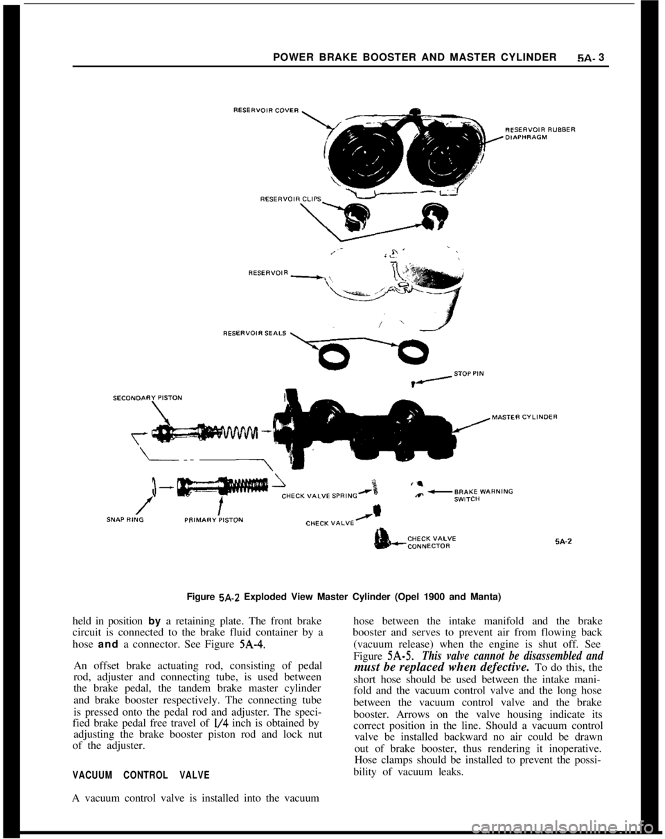
Figure 5A-2 Exploded View Master Cylinder (Opel 1900 and Manta)
held in position by a retaining plate. The front brake
circuit is connected to the brake fluid container by a
hose and a connector. See Figure
5A-4.An offset brake actuating rod, consisting of pedal
rod, adjuster and connecting tube, is used between
the brake pedal, the tandem brake master cylinder
and brake booster respectively. The connecting tube
is pressed onto the pedal rod and adjuster. The speci-
fied brake pedal free travel of
l/4 inch is obtained by
adjusting the brake booster piston rod and lock nut
of the adjuster.
VACUUM CONTROL VALVEhose between the intake manifold and the brake
booster and serves to prevent air from flowing back
(vacuum release) when the engine is shut off. See
Figure 5A-5.
This valve cannot be disassembled andmust be replaced when defective. To do this, the
short hose should be used between the intake mani-
fold and the vacuum control valve and the long hose
between the vacuum control valve and the brake
booster. Arrows on the valve housing indicate its
correct position in the line. Should a vacuum control
valve be installed backward no air could be drawn
out of brake booster, thus rendering it inoperative.
Hose clamps should be installed to prevent the possi-
bility of vacuum leaks.
A vacuum control valve is installed into the vacuum