lock OPEL GT-R 1973 Service Manual
[x] Cancel search | Manufacturer: OPEL, Model Year: 1973, Model line: GT-R, Model: OPEL GT-R 1973Pages: 625, PDF Size: 17.22 MB
Page 420 of 625
AUTOMATIC TRANSMISSION7c- 59
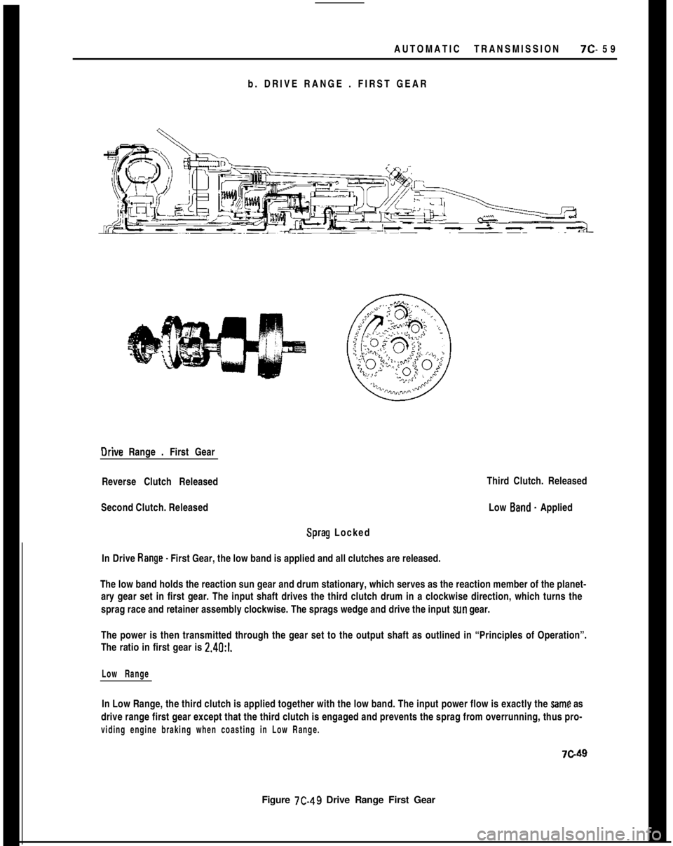
b. DRIVE RANGE . FIRST GEAROrive Range . First Gear
Reverse Clutch Released
Second Clutch. Released
Sprag Locked
In Drive Range. First Gear, the low band is applied and all clutches are released.
Figure 7C-49 Drive Range First GearThird Clutch. Released
Low Band. Applied
The low band holds the reaction sun gear and drum stationary, which serves as the reaction member of the planet-
ary gear set in first gear. The input shaft drives the third clutch drum in a clockwise direction, which turns the
sprag race and retainer assembly clockwise. The sprags wedge and drive the input
sun gear.
The power is then transmitted through the gear set to the output shaft as outlined in “Principles of Operation”.
The ratio in first gear is 2.4O:l.
Low RangeIn Low Range, the third clutch is applied together with the low band. The input power flow is exactly the
Same as
drive range first gear except that the third clutch is engaged and prevents the sprag from overrunning, thus pro-
viding engine braking when coasting in Low Range.
7c49
Page 421 of 625

7C- 601973 OPEL SERVICE MANUAL
c. DRIVE RANGE. SECONO GEAROrive Range . Second Gear
Reverse Clutch - Released
Second Clutch -Applied
Sprag
- Overrunning
In Drive Range. Second Gear, the low band and second clutch are applied.Third Clutch
- Released
Low Band -Applied
The input shaft drives the third clutch drum and the second clutch composition plates. When the second clutch
piston is applied, the rotating second clutch composition plates are locked
w the second clutch steel plates. Since
the second clutch drum is now rotating in a clockwise direction, the ring gear is driven clockwise. As described in
“Principles of Operation”, the carrier is driven in a clockwise direction. The long planet pinions also drive the
short planet pinions, which drive the input sun gear clockwise, causing the sprag assembly to overrun. The ratio
is 1.48:1.
second Range
In Second Range, the Power flow is exactly the seme as drive range - second gear.7c50
Figure
7C-50 Drive Range - Second Gear
Page 422 of 625

AUTOMATIC TRANSMISSION 7C- 61
d. DRIVE RANGE - THIRD GEAR
Drive Range
- Third Gear
Reverse Clutch
- Released
Second Clutch. Applied
Sprag . LockedThird Clutch -Applied
Low Band
- Released
In Drive Range
- Third Gear, the low band is released and both the second and third clutches are applied.
In this condition, the ring gear is locked o the input sun gear. With two planetary members connected
inthismanner, the entire planetary system will rotate as a solid unit and provide a direct drive with a ratio of 1 to 1. The
input is split between the ring gear end input sun, and the rarrier is the output member.
Figure 7C-5 1 Drive Range Third Gear
Page 426 of 625
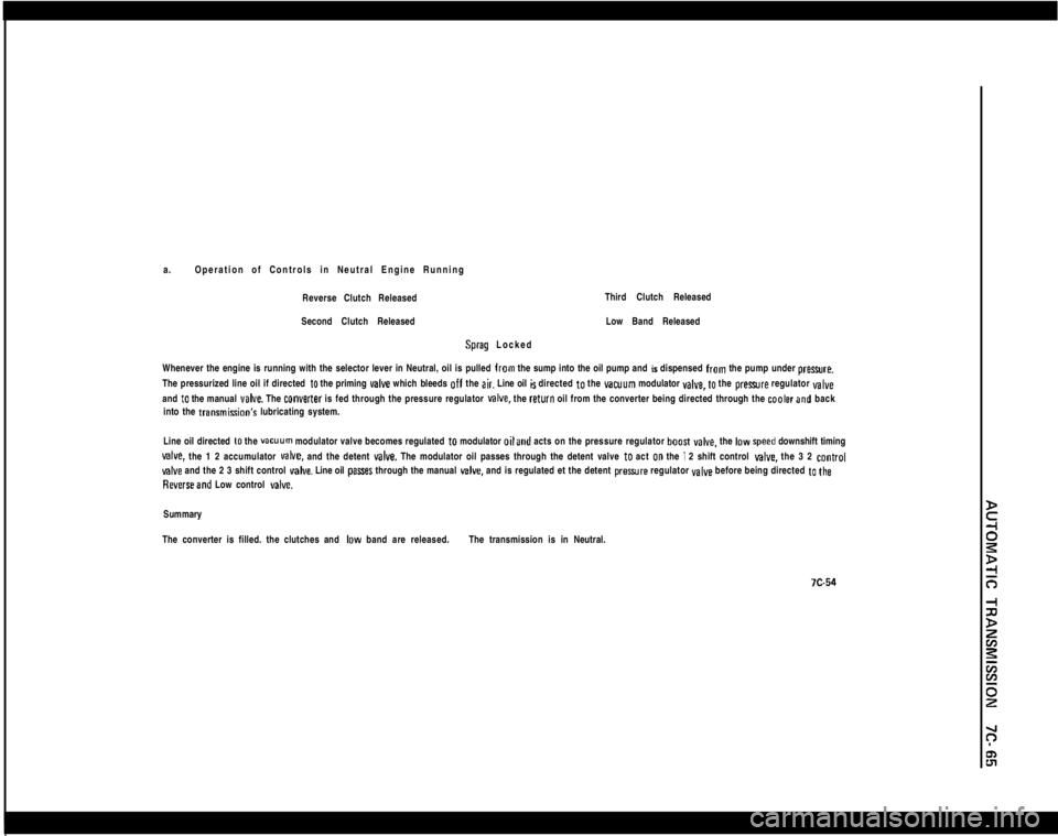
a.Operation of Controls in Neutral Engine Running
Reverse Clutch ReleasedThird Clutch Released
Second Clutch ReleasedSprag LockedLow Band Released
Whenever the engine is running with the selector lever in Neutral, oil is pulled from the sump into the oil pump and is dispensed from the pump under preure.
The pressurized line oil if directed
to the priming valve which bleeds off the air. Line oil is directed to the vacuum modulator YBIYB, to the prexwre regulator valveand
to the manual veIve. The converter is fed through the pressure regulator MIYB. the return oil from the converter being directed through the coalerand back
into the transmisGon’s lubricating system.
Line oil directed
to the vacuum modulator valve becomes regulated to modulator oiland acts on the pressure regulator boosI YBCB. the IDW speed downshift timing
valve. the 1 2 accumulator MIYB. and the detent valve. The modulator oil passes through the detent valve to act 00 the I 2 shift control give. the 3 2 control
valve and the 2 3 shift control valve. Line oil pasres through the manual v&e. and is regulated et the detent preaure regulator valve before being directed to the
Reverseand Low control delve.Summary
The converter is filled. the clutches and
IDW band are released.The transmission is in Neutral.
Page 432 of 625
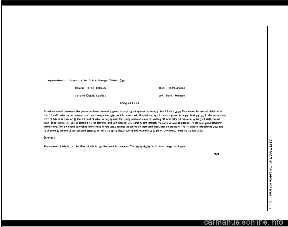
d. Operation of Controls in Drive Range Third Geat
Reverse Clutch ReleasedThird Clutch-Applied
Second Clutchs AppliedLow Band Released
Sprag Locked
As vehicle speed increases. the governor allows more oil to pass through to act against the wring
at the 2 3 shift valve. This allows the second clutch oil at
the 2 3 shift valve
10 be released and pan through the valve as third clutch oil, directed tothe third clutch piston to apply third clutch. At the same time,
third clutch oil is directed
to the 3 2 control valve. acting against the spring and modulator oil. cutting off modulator oil pressure to the 2. 3 shift controlyalve. Third control oil also is directed to the Reverse and Law control valve and pasts through thevalveasservo release oil to the lowspeed downshift
timing valve. The low speed downshih timing valve is held
open against the spring by increased modulator oil pressure. The oil passes through the valve and
is directed
to the top of the low band sewo. to act with the servo piston spring and force the sel~o piston downward. releasing the low band.
The second clutch is on, the third clutch is on, the band is released. The transmikn is in drive range third gear
Page 436 of 625
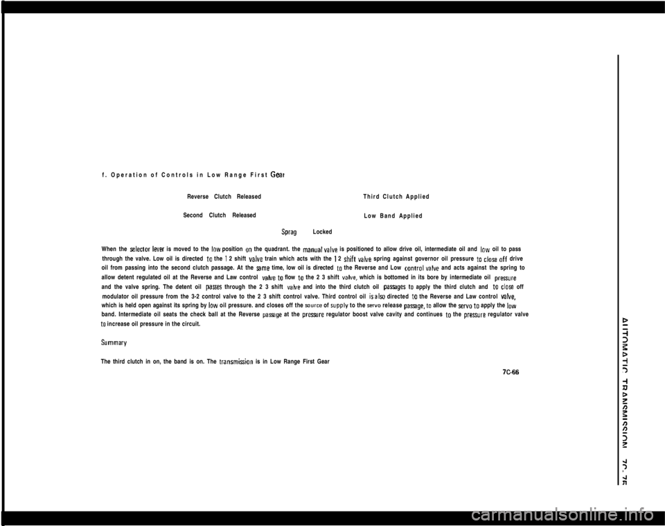
f. Operation of Controls in Low Range First GeaReverse Clutch ReleasedThird Clutch Applied
Second Clutch Released
Low Band Applied
Sprag Locked
When the
selector lever is moved to the low position on the quadrant. the manualvalve is positioned to allow drive oil, intermediate oil and low oil to pass
through the valve. Low oil is directed to the
1 2 shift valve train which acts with the I 2 shift valve spring against governor oil pressure to close off drive
oil from passing into the second clutch passage. At the
same time, low oil is directed to the Reverse and Low control valve and acts against the spring to
allow detent regulated oil at the Reverse and Law control
valve to flow to the 2 3 shift valve, which is bottomed in its bore by intermediate oil pressxeand the valve spring. The detent oil
pazses through the 2 3 shift vahre and into the third clutch oil passages to apply the third clutch and to close off
modulator oil pressure from the 3-2 control valve to the 2 3 shift control valve. Third control oil isalSo directed to the Reverse and Law control
valve.which is held open against its spring by low oil pressure. and closes off the
source of rupply to the servo release pasege. to allow the servo to apply the low
band. Intermediate oil seats the check ball at the Reverse
passage at the presue regulator boost valve cavity and continues to the pressure regulator valve
to increase oil pressure in the circuit.
iThe third clutch in on, the band is on. The transmi&n is in Low Range First Gear
Page 438 of 625
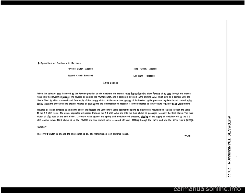
9. Operation of Controls in Reverse
Reverse Clutch -Applied
Second Clutch Released
Sprag LockedThird Clutch. Applied
Low Band. Released
When the selector leer is moved to the Reverse position on the quadrant, the manual
valve ispositioned to allow Revert oil to pars through the manual
valve into the
Reverse oil passage. The reverse oil applies the reverse clutch. and a portion is directed to the priming valve which acts as a damper until the
line is filled. to effect a smooth and firm apply of the
reverss clutch. At the wne time, reverse oil is directed to the pressure regulator boost control valve
cavity to seat the check ball and prevent reverse oil pasring into the intermediate oil passage. It is then directed to the pressure regulator boast valve forcing
Reverse oil is also directed to act on the end of the
Reverse and Law control valve against the spring to allow detent regulated oil to pass through the valveto the 2 3 shift
valve. The detent regulated oil passes through the 2 3 shift valve and into the third clutch oil passages to apply the third clutch. The third
clutch oil
al= acts on the end of the 3 2 control valve against the spring and modulator oil pressure, clodng off the supply of modulator oil to the 2 3
shift control valve. Third clutch oil at the rwerse and low control valve is closed off from
parring through the valve. and into the servo releal~ parrage.Summary
The
reverse clutch is cm and the third clutch is on. The transmission is in Reverse Range.
Page 445 of 625

7C. 841973 OPEL SERVICE MANUALConditionCause8. No starting in “R” range
(proper driving in all other
ranges).a) Reverse clutch failure.
9. Drive in selector lever
position “N”.a) Inadequate selector lever linkage.
b) Planetary gear set broken.
c) Improper adjustment of band.
Gear Change1. No l-2 upshift in “D” and “S”
(transmission remains in 1st gear
at all speeds).a) Governor valves stuck.
b) 1-2 shift valve stuck in 1st gear
position.
c) Seal rings (oil pump hub) leaky.
d) Large leak in governor pressure circuit.
e) Governor screen clogged.
2. No 2-3 upshift in “D” (trans-
mission remains in 2nd gear at all
speeds).a) 2-3 shift valve stuck.
b) Large leak in governor pressure circuit.
3. Upshifts in “D” and “S” only
at full throttle.a) Failed vacuum modulator.
b) Modulator vacuum line leaky or
interrupted.
c) Leak in any part of engine or
accessory vacuum system.
d) Detent valve or cable stuck.
4. Upshifts in “D” and “S” only
at part throttle (no detent
upshift).a) Detent pressure regulator valve stuck.
b) Detent cable broken or misadjusted.
5. Driving only in 1st gear of
“D” and “S” range (transmission
blocks in 2nd gear and “R”).a) “L” and “R” control valve stuck in
“L” or “R” position.
6. No part throttle 3-2 downshift
at low vehicle speeds.a) 3-2 downshift control valve stuck.
7. No forced downshift.a) Detent cable broken or improperly
adjusted.
b) Detent pressure regulator valve stuck.
Page 447 of 625
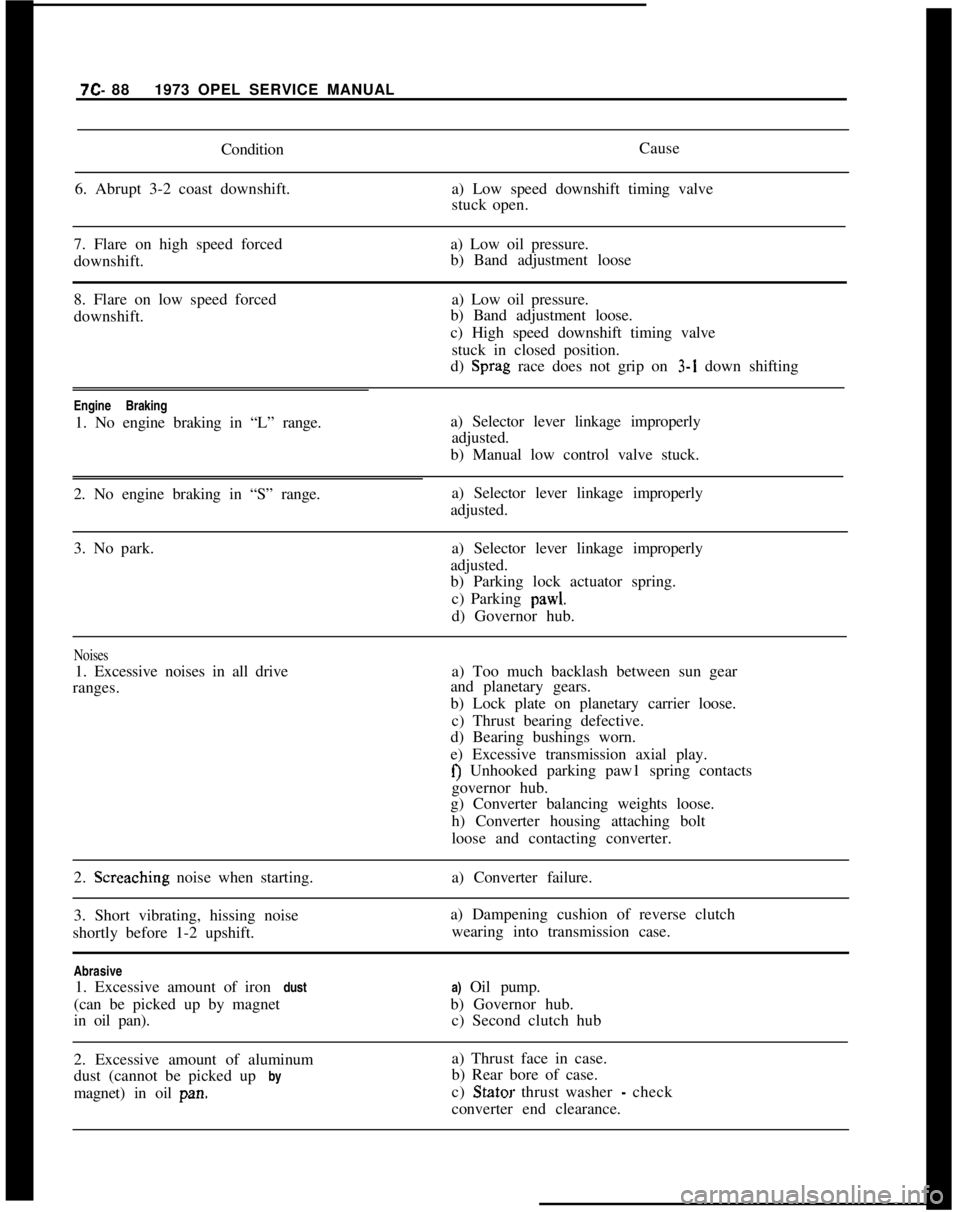
7C- 881973 OPEL SERVICE MANUAL
Condition
6. Abrupt 3-2 coast downshift.Cause
a) Low speed downshift timing valve
stuck open.
7. Flare on high speed forceda) Low oil pressure.
downshift.b) Band adjustment loose
8. Flare on low speed forced
downshift.a) Low oil pressure.
b) Band adjustment loose.
c) High speed downshift timing valve
stuck in closed position.
d) Sprag race does not grip on 3-1 down shifting
Engine Braking
1. No engine braking in “L” range.a) Selector lever linkage improperly
adjusted.
b) Manual low control valve stuck.
2. No engine braking in “S” range.a) Selector lever linkage improperly
adjusted.
3. No park.a) Selector lever linkage improperly
adjusted.
b) Parking lock actuator spring.
c) Parking pawl.
d) Governor hub.
Noises1. Excessive noises in all drive
ranges.a) Too much backlash between sun gear
and planetary gears.
b) Lock plate on planetary carrier loose.
c) Thrust bearing defective.
d) Bearing bushings worn.
e) Excessive transmission axial play.
f) Unhooked parking paw1 spring contacts
governor hub.
g) Converter balancing weights loose.
h) Converter housing attaching bolt
loose and contacting converter.
2. Screaching noise when starting.
3. Short vibrating, hissing noise
shortly before 1-2 upshift.a) Converter failure.
a) Dampening cushion of reverse clutch
wearing into transmission case.
Abrasive
1. Excessive amount of iron dust
(can be picked up by magnet
in oil pan).a) Oil pump.
b) Governor hub.
c) Second clutch hub
2. Excessive amount of aluminum
dust (cannot be picked up by
magnet) in oil pan.a) Thrust face in case.
b) Rear bore of case.
c) Stator thrust washer
- check
converter end clearance.
Page 452 of 625

AUTOMATIC TRANSMISSION 7C- 91
MAINTENANCE AND ADJUSTMENTS
DETENT CABLE REPLACEMENT AND
ADJUSTMENT
The reliability of the detent bowden control cable is
greatly dependent upon the proper adjustment of the
wire whenever installation is being made. It is impor-
tant to remember that the free end of the wire is not
kinked, as individual strands will break due to the
continuous bending during operation. To avoid this
situation, it is important that the bowden control
cable be properly installed. Although replacement
and adjustment procedures on various models are
identical, the location of the upper, or throttle, end
of the detent cable may vary. For proper model iden-
tification, see Figures
7C-61, 7C-62, 7C-63, and 7C-
64.Figure JC-79 Opel 1900 and Manta
Figure
7~80 Opel 1900 and MantaFigure JC-81 GT Models
Figure JC-93 GT Models
Removal
I. Detach retainer at detent cable to accelerator link-
age.2. Loosen rear transmission crossmember from body
and remove right side bolt. See Figure
7C-84, Callout
” A ”3. Insert block of wood between floor pan and right
rear corner of transmission to expose detent cable
bracket at transmission. See Figure
7C-85.4. Unscrew detent cable connecting retainer from
transmission and pull cable out of transmission. See
Figure
7C-86.