turn signal OPEL GT-R 1973 User Guide
[x] Cancel search | Manufacturer: OPEL, Model Year: 1973, Model line: GT-R, Model: OPEL GT-R 1973Pages: 625, PDF Size: 17.22 MB
Page 99 of 625

I i--
LI
.
lJ- 78 1873 OPEL SERVICE~MANUAL’
Figure lJ-5 Turn
Signal and Hazard Flasher - GT
Page 197 of 625

3D- 301973 OPEL SERVICE MANUALFigure 3D-8 - Removing Clamp Bolt3. Remove cotter pin located on left and right tie rod
end and unscrew nut.
4. Using Tool J-21687, press tie rod ends out of
steering arms.
5. Disconnect steering gear housing from front sus-
pension cross member and remove steering gear
together with tie rods.
Installation . GTCAUTION: Fasteners are important attaching parts in
that they could affect the performance of vital com-
ponents and systems, and/or could result in major
repair expense. They must be replaced
with one of
the same part number or with an equivalent part if
replacement becomes necessary. Do not
use a re-
placement part of lesser quality or substitute design.
Torque values must be used as specified during reas-
sembly to assure proper retention of these parts.
1. Position steering gear on front suspension cross
member and torque attaching bolts to 18
lb.ft.2. Position tie rod ball studs in steering arms; install
nuts and torque to 29 lb.ft. Lock in position with new
cotter pins.
3. Fully turn steering wheel so that flat or cutout
surface on lower portion of steering shaft is parallel
to flexible coupling bolt hole.
4. Install the lower end of steering shaft to the flexi-
ble coupling and adjust dimension between steering
wheel hub and direction signal switch housing cover
to
l/8 and 3/32 inch. Maintain adjustment by tight-
ening flexible coupling bolt and nut to 15 lb.ft. Lock
the bolt and nut in position with lock-plate tabs.5. Reinstall stop bolt into steering column.
6. Full turn steering wheel both right and left. If any
resistance is noticeable, it will be necessary to remove
the sleering column and correct the cause.
D. Installation (Opel 1900. Manta)CAUTION: Fasteners are important attachingparts in
that they could affect the performance of vital com-
ponents and systems, and/or could result in
maJbrrepair expense. They must be replaced with one of
the same part number or with an equivalent part if
replacement becomes necessary. Do not use a re-
placement part oflesser
quaky or substitute design.
Torque values must be used as specified during reas-
sembly to assure proper retention of these parts.
1. Prior to installation, set steering gear to high
point. The steering wheel spokes point downwards in
an oblique angle. The elongated cutout of the lower
steering mast must coincide with the clamp bolt hole
of the pinion flange.
2. Position steering gear on front suspension cross
member and torque attaching bolts to 29 lb.ft.
3. Position tie rod studs in steering arms. Install nuts
and torque to 29
Ib.ft. Lock in position with new
cotter pin.
4. Install the lower end of the steering shaft to flexi-
ble coupling and torque clamp bolt to 22
lb.ft.5. Attach guard plate to both side members and
lower deflector panel.
DISASSEMBLY AND ASSEMBLY OF
STEERING GEAR ASSEMBLY WITH TIE RODS
Disassembly - GT1. Carefully clamp gear assembly in soft jaw vise and
slip clamps and rubber bellows off gear housing to
expose area where ball joint screws into rack.
2. Bend up round edges of lockplates from tie rod
ball studs and disconnect tie rod ball studs from rack.
See Figure
3D-9). It is important that rack be held
secure with open end wrench to prevent damage to
rack teeth.
3. Loosen adjusting screw lock nut; remove adjusting
screw from steering gear housing, and take out thrust
spring and sintered bronze shell. See Figure
3D-11.4. Rotate gear assembly in vise so that pinion shaft
portion of assembly is held by vise, and remove pin-
ion nut, flat washer, and special washer.
Page 203 of 625

3E- 361973 OPEL SERVICE MANUAL
and ignition switch in RUN position, the fog lights
are automatically switched off. Direction signals
work in the normal manner; pushing the lever up for
right turn signal and pulling the lever down for left
turn signal.
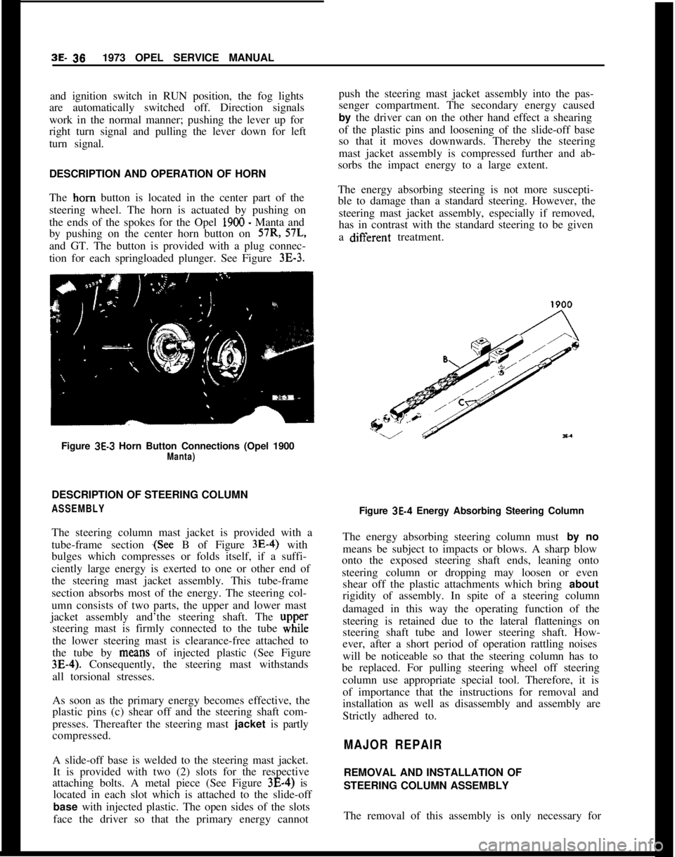
DESCRIPTION AND OPERATION OF HORN
The horn button is located in the center part of the
steering wheel. The horn is actuated by pushing on
the ends of the spokes for the Opel 1900 - Manta and
by pushing on the center horn button on 57R, 57L,
and GT. The button is provided with a plug connec-
tion for each springloaded plunger. See Figure
3E-3.Figure
3E-3 Horn Button Connections (Opel 1900Manta)DESCRIPTION OF STEERING COLUMN
ASSEMBLYThe steering column mast jacket is provided with a
tube-frame section
.(See B of Figure 3E-4) with
bulges which compresses or folds itself, if a suffi-
ciently large energy is exerted to one or other end of
the steering mast jacket assembly. This tube-frame
section absorbs most of the energy. The steering col-
umn consists of two parts, the upper and lower mast
jacket assembly and’the steering shaft. The
upp,ersteering mast is firmly connected to the tube while
the lower steering mast is clearance-free attached to
the tube by means of injected plastic (See Figure
3E-4). Consequently, the steering mast withstands
all torsional stresses.
As soon as the primary energy becomes effective, the
plastic pins (c) shear off and the steering shaft com-
presses. Thereafter the steering mast jacket is partly
compressed.
A slide-off base is welded to the steering mast jacket.
It is provided with two (2) slots for the respective
attaching bolts. A metal piece (See Figure 3E-4) is
located in each slot which is attached to the slide-off
base with injected plastic. The open sides of the slots
face the driver so that the primary energy cannotpush the steering mast jacket assembly into the pas-
senger compartment. The secondary energy caused
by the driver can on the other hand effect a shearing
of the plastic pins and loosening of the slide-off base
so that it moves downwards. Thereby the steering
mast jacket assembly is compressed further and ab-
sorbs the impact energy to a large extent.
The energy absorbing steering is not more suscepti-
ble to damage than a standard steering. However, the
steering mast jacket assembly, especially if removed,
has in contrast with the standard steering to be given
a difierent treatment.
Figure
3E-4 Energy Absorbing Steering Column
The energy absorbing steering column must by no
means be subject to impacts or blows. A sharp blow
onto the exposed steering shaft ends, leaning onto
steering column or dropping may loosen or even
shear off the plastic attachments which bring about
rigidity of assembly. In spite of a steering column
damaged in this way the operating function of the
steering is retained due to the lateral flattenings on
steering shaft tube and lower steering shaft. How-
ever, after a short period of operation rattling noises
will be noticeable so that the steering column has to
be replaced. For pulling steering wheel off steering
column use appropriate special tool. Therefore, it is
of importance that the instructions for removal and
installation as well as disassembly and assembly are
Strictly adhered to.
MAJOR REPAIRREMOVAL AND INSTALLATION OF
STEERING COLUMN ASSEMBLY
The removal of this assembly is only necessary for
Page 205 of 625

3E- 38 ,1973 OPEL SERVICE MANUAL
ponents and systems, and/or could result in major
repair expense. They must be replaced with one or
the same part number or with
an equivalent part if
replacement becomes necessary. Do not use a
re-
placement part of lesser quality or substitute design.
Torque
values must be used as specified during reas-
sembly to assure proper retention of these parts.On installation, make sure steering wheel spokes
point downwards and steering gear is in high point.
1. Carefully insert steering mast into universal joint
flange.
2. Loosely attach slide-off base attaching nuts at un-
derside of instrument panel.
3. Attach steering mast jacket at front of dash, using
a notched hex nut.
4. Torque nuts at slide-off base to II
lb.ft.5. Tighten screw at steering mast clamp to 22
lb.ft.6. Reconnect wires to directional signal switch and
ignition switch.
7. Reconnect battery.
REMOVAL AND INSTALLATION OF
STEERING WHEELThis procedure may be performed with the steering
column assembly either removed or installed in the
car.
Removal
1. Disconnect battery.
2. Pry off horn cap and remove wires from cap. See
Figure
3E-3.3. Bend lockplate tabs down and take off steering
shaft nut and lockplate.
4. Install steering wheel remover J-21686 as shown
in Figure
3E-9 and pull off steering wheel.
Installation1. Before installing steering wheel, lubricate return
pin and sliding area on directional signal switch re-
turn cams and horn contact ring.
2. Make sure that clamp bolt in steering shaft flange
is on top.
3. Make sure notch on steering shaft face is in hori-
zontal position.Figure
3E-9 Removing Steering Wheel
4. With the steering wheel centered, place the steer-
ing wheel onto the steering shaft.
5. Install steering wheel lockplate and nut. Torque to
11
lb.ft.
CAUTION:
This steering wheeI to steering shaft fas-
tener is an important attaching part in that it could
affect the
performance of vital components and sys-
tems, and/or could result in major repair expense. It
must be repked
with one of the same part number
or with an equivalent part if replacement becomes
necessary. Do not use a replacement part of lesser
quality or substitute design. Torque
values must be
used as specified during reassembly to assure proper
retention of this part.6. Bend lockplate tabs up, connect horn cap wires
and replace cable and cap.
7. Reconnect battery.
REMOVAL AND REPLACEMENT OF HORN
CONTACT RING
1. Remove steering wheel.
2. Cut off defective contact ring at wire.
3. Strip wire approximately
l/8”.4. Install new part and solder connection with resin
core solder.
5. Lubricate contact ring with lubriplate, or equiva-
lent.
6. Reinstall steering wheel.
Page 207 of 625

3E- 40 1973 OPEL SERVICE MANUAL
on steering and ignition lock bracket using a new
tear-off bolt (hexagon head tears
ofD.
3. Disconnect slide-off base, install upper half of sig-
nal switch housing cover, and loosely reattach
slide-
off base.
4. Attach steering mast jacket at front of dash panel.
See Figure
3E-7.
5. Torque slide-off base attaching nuts to 11 lb.ft.
6. Install lower half of signal switch housing cover
and connect signal switch, as well as steering ignition
lock wire set.
7. Install steering wheel and torque nut to 11
Ib.ft.
Always use new lock plate.
DISASSEMBLY AND REASSEMBLY OF STEERING
AND IGNITION LOCK CYLINDER AND ELECTRICAL SWITCH FROM MAST JACKET
ASSEMBLY
Disassembly. GT
Disconnect the battery before proceeding.
1. Remove steering wheel.
2. Turn ignition switch to ON position.
3. Insert a suitable rod into stop pin hole on side of
steering and ignition lock (See Figure
3E-13) and
take out steering and ignition lock cylinder. 4. Remove two screws securing electrical switch to
steering and ignition lock housing and take out
switch.
Disassembly (Opel 1900 . Manta)
1. Rezmove steering wheel.
2. Unscrew split signal switch housing cover and
remove lower half. See Figure
3E-10.
3. Remove lock cylinder by pushing in lock spring of
the cylinder using a piece of wire. Cylinder must be
in the
” 1” position. See Figure 3E-14.
Figure 3E-14 Removing Lock Cylinder
Reassembly
1. On the GT reassemble electrical switch into steer-
ing and ignition
lock housing and rotate switch until:
(1) cam in lock housing recess fits into slotted hole
in rear of electrical switch, and (2) projection on
electrical switch fits into recess on lock housing.
2. On the Opel 1900
- Manta, insert lock cylinder in
the
P l* position into housing. Install lower half of
signal switch housing.
3. Reinstall steering wheel.
Figure 3E-13 Removing Ignition Lock Cylinder
Page 212 of 625

GT STEERING COLUMN ASSEMBLY3E- 45
loose must never be done. The only recommendation
for freeing frozen steering wheels is to use a penetrat-
ing lubricant.Installation1. Before installing steering wheel, lubricate return
pin and slide area on direction signal switch return
cams and horn ring contact.
2. With steering wheel properly aligned to shaft, in-
stall lockplate and nut. Torque nut to 15
Ib.ft.
CAUTION:
This steering wheel to steering shafi fas-
tener is an important attac&ng part in that it could
affect the performance of vital components and sys-
tems, and/or could result in major repair expense. It
must be
rep/aced with one of the same part number
or with an equivalent part, if replacement becomes
necessary. Do not use a replacement part of lesser
quality or substitute design. Torque values must be
used as specified during reassembly to assure proper
retention of this part.3. Bend up lockplate tab and install horn cap.
4. Reconnect battery.
REMOVAL AND INSTALLATION OF IGNITION
LOCK CYLINDER
RemovalThis procedure may be performed with the steering
column assembly either removed or installed in the
car.1. Remove steering wheel, as outlined previously in
this Group.
2. Position lock cylinder to run position.
3. Using suitable piece of wire, push in lock cylinder
retaining pin and remove lock cylinder. See Figure3E- 18.
Installation1. Insert lock cylinder into lock cylinder housing.
2. Install steering wheel, as outlined previously in
this section.
REMOVAL AND INSTALLATION OF STEERING
COLUMN ASSEMBLY
Removal1. Position steering so that front wheels are straight
ahead.Figure
3E-18 Removing Lock Cylinder
2. Loosen steering shaft upper universal joint lower
clamp bolt. See Figure
3E-19.3. Drill off heads of both tear bolts by first drilling
an 3/16 inch pilot hole and then inserting a
l/4 inch
bolt extractor to remove lockbolt.
4. Disconnect ignition (white) and direction signal
(black) wire set plugs.
5. Support steering column assembly and remove
both hex. head bolts.
6. Pull steering column assembly off center steering
shaft. Do not apply any force as plastic injections in
center steering shaft may be loosened and shaft
would then require replacement.
Installation
CAUTION:
Fasteners are important attachingparts in
that they
cooId affect the performance of vital com-
ponents and systems, and/or could result in major
repair expense. They must be replaced with one of
the same part number or with an equivalent part if
replacement becomes necessary. Do not use a re-
placement part of lesser quality or
substitute design.
Torque values must be used as specified during
reas-
sembIy to assure proper retention of these parts.1. Install steering column assembly onto steering
shaft and torque steering shaft upper universal joint
lower clamp bolt to 14
lb.ft.2. Install hex head bolts and torque to 14
lb.ft.
NOTE:
Be sure to install ground wire.
Page 214 of 625

GT STEERING COLUMN ASSEMBLY3E- 47
2. Disconnect ignition (white) wire set plug.
3. Remove steering lock retaining screw. See Figure3E-20.Figure 3E-20 Steering Lock Retaining Screw
4. Remove direction signal switch lever.
5. Remove three screws securing signal switch cover
to housing.
6. To remove housing cover, (a) pull cover toward
direction signal switch and move it slightly to the
right. See Figure
3E-21. (b) Turn cover toward the
left and move it further to the right so that the left
retaining screw ear is positioned under the left signal
switch return cam. See Figure
3E-22. (c) Insert direc-
Figure 3E-2 1tion signal switch lever into oblong opening in cover
and push steering lock into housing and remove
cover. See Figure
3E-37.Figure
3E-22Figure 3E.23
7. Remove ignition switch electrical unit. See Figure3B24.
8. Remove wires from connector plug making certain
to note location of each.
9. Tape wire ends together and remove electrical unit
and wire harness.
Installation1. Position electrical unit wire harness through col-
umn and reconnect to connector plug.
Page 215 of 625

3E- 481973 OPEL SERVICE MANUAL
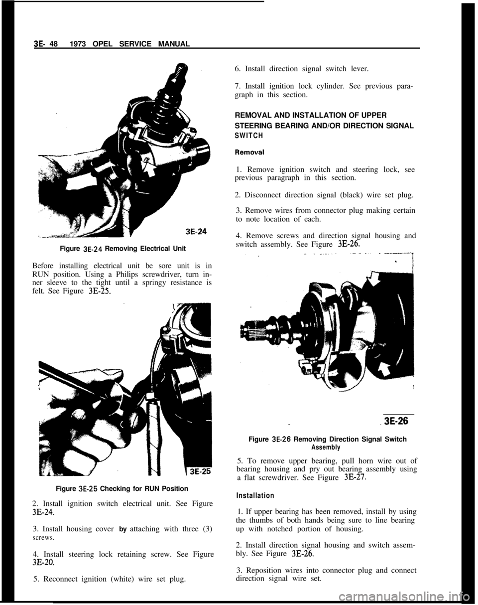
Figure 3E-24 Removing Electrical Unit
Before installing electrical unit be sore unit is in
RUN position. Using a Philips screwdriver, turn in-
ner sleeve to the tight until a springy resistance is
felt. See Figure 3E-25.Figure 3E-25 Checking for RUN Position
2. Install ignition switch electrical unit. See Figure
3E-24.3. Install housing cover by attaching with three (3)
screws.4. Install steering lock retaining screw. See Figure
3E-20.5. Reconnect ignition (white) wire set plug.6. Install direction signal switch lever.
7. Install ignition lock cylinder. See previous para-
graph in this section.
REMOVAL AND INSTALLATION OF UPPER
STEERING BEARING AND/OR DIRECTION SIGNAL
SWITCH1. Remove ignition switch and steering lock, see
previous paragraph in this section.
2. Disconnect direction signal (black) wire set plug.
3. Remove wires from connector plug making certain
to note location of each.
4. Remove screws and direction signal housing and
switch assembly. See Figure
3E-26.
..3E-26
Figure 3E-26 Removing Direction Signal Switch
Assembly5. To remove upper bearing, pull horn wire out of
bearing housing and pry out bearing assembly using
a flat screwdriver. See Figure
3E-27.
Installation1. If upper bearing has been removed, install by using
the thumbs of both hands being sure to line bearing
up with notched portion of housing.
2. Install direction signal housing and switch assem-
bly. See Figure 3B26.
3. Reposition wires into connector plug and connect
direction signal wire set.
Page 517 of 625

9A-8 1973 OPEL SERVICE MANUAL
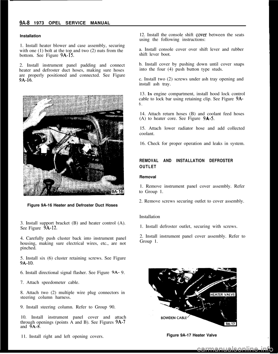
Installation
1. Install heater blower and case assembly, securing
with one (1) bolt at the top and two (2) nuts from the
bottom. See Figure
9A-15.
2. Install instrument panel padding and connect
heater and defroster duct hoses, making sure hoses
are properly positioned and connected. See Figure
9A-16.
Figure 9A-16 Heater and Defroster Duct Hoses
3. Install support bracket (B) and heater control (A).
See Figure
9A-12.
4. Carefully push cluster back into instrument panel
housing, making sure electrical wires, etc., are not
pinched.
5. Install six (6) cluster retaining screws. See Figure
9A-10.
6. Install directional signal flasher. See Figure
9A- 9.
7. Attach speedometer cable.
8. Attach two (2) multiple wire plug connectors in
steering column harness.
9. Install steering column. Refer to Group 90.
10. Install instrument panel cover and attach
through openings (points A and B). See Figures
9A-7
and 9A-8.
11. Install right and left opening covers. 12. Install the console shift
cover
between the seats
using the following instructions:
a. Install console cover over shift lever and rubber
shift lever boot.
b. Install cover by pushing down until cover snaps into the four (4) push button type studs.
c. Install two (2) screws under ash tray opening and
install ash tray. 13.
In engine compartment, install hood lock control
cable to lock bar using retaining clip. See Figure
9A-
6.
14. Attach return hoses (B) and coolant feed hoses
(A) to heater core. See Figure
9A-5.
15. Attach lower radiator hose and add collected
coolant.
16. Check for proper operation and leaks in system.
REMOVAL AND INSTALLATION DEFROSTER
OUTLET
Removal
1. Remove instrument panel cover assembly. Refer
to Group 1.
2. Remove screws securing outlet to cover assembly.
Installation1. Install defroster outlet, securing with screws.
2. Install instrument panel cover assembly. Refer to
Group 1.
Figure 9A-17 Heater Valve
Page 624 of 625

SubjectPage Number1
Throttle Linkage Adjustment........,:.......6E-51
Timing Chain Cover.......................6A-23
Timing Chain and Sprocket.........
':.......6A-23
Tires...................................36-55
Inflation.....................
.;.......3G-62
Rotation.............................36-57
Sizes.........................
........3G-62
Track Rod..............................3F-53
Transmission Oil Pan
Automatic Transmission.................7C-99
Transmission Reassembly
4 Speed Manual. 1.9.....................76-28Tranmission Removal and Installation
4 Speed Manual
Removal...........................7B-22
Installation.........................76-22
Auto&tic............................7c-94Tune’Up Procedure........................66-65
Torque Specifications. Engine...............6A-27
Turn Signal See Directional Signal
Universal Joints..........................4A-3Subject
VPage Number
Vacuum Modulator..7C-101
Valve Body Transmlssmn7C.99
Valve and Seat Reconditioning Engine6A-12
WWater Pump Engine1.9L Engine
Wheels
Wheel Alignment
Whee! Bearing, Adjustment,
Windshield Wiper and Washer:
Trouble Diagnosis:Description and Operation
Removal and Installation
Specifications
Wiring Diagrams Complete
Opel 1900 ._.
Manta
GT
1 E-37
1 E-37
1 E-38
1 E-43
1 J-l 03
1 J-l 05lJ-10768-3436-553C-223A-4