96-80 1973 OPEL SERVICE MANUAL
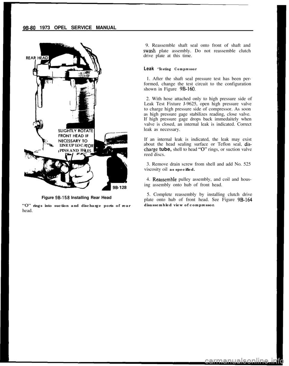
LINE UP LOCA
PINS AND
HOFigure SB-158 Installing Rear Head
“0” rings into suction and discharge ports of rear
head.9. Reassemble shaft seal onto front of shaft andwash plate assembly. Do not reassemble clutch
drive plate at this time.
Leak ‘Testing Compressor1. After the shaft seal pressure test has been per-
formed, change the test circuit to the configuration
shown in Figure 9B-160.
2. With hose attached only to high pressure side of
Leak Test Fixture J-9625, open high pressure valve
to charge high pressure side of compressor. As soon
as high pressure gage stabilizes reading, close valve.
If high pressure gage drops back immedaitely when
valve is closed, an internal leak is indicated. Correct
leak as necessary.
If an internal leak is indicated, the leak may exist
about the head sealing surface or Teflon seal,
dis-
charg,e tube, shell to head “0” rings, or suction valve
reed discs.
3. Remove drain screw from shell and add No. 525
viscosity oil as specified.
4.
R~eassemble pulley assembly, and coil and hous-
ing assembly onto hub of front head.
5. Complete reassembly by installing clutch drive
plate onto hub of front head. See Figure 9B-164
disassembled view of compressor.
