tow OPEL GT-R 1973 Service Manual
[x] Cancel search | Manufacturer: OPEL, Model Year: 1973, Model line: GT-R, Model: OPEL GT-R 1973Pages: 625, PDF Size: 17.22 MB
Page 27 of 625

j
/lA- 61973 OPEL SERVICE MANUAL
Do not overfill, as electrolyte may
be sprayed out by
gassing or may overtlow due to heat expansion dur:
ing charging.
If distilled water is not available, it is better to add
clean, mineral-free tap water than to allow the
elec2trolyte level to remain below the top of the plates:
In freezing weather the water should be added just
before using the car or otherwise charging the bat-
tery so that the water will be mixed with the acid
before it is allowed to stand in freezing temperatures.
If it is found necessary to add water to the
batterimore frequently than about every
1,ooO miles and the
quantity of water added per cell is’ excessive, check
setting of voltage regulator and adjust, if necessary:
Abnormal water loss is an indication that the battery
is being overcharged.
Inspect Battery, Mounting and Cables
Check outside of battery for damage or signs of se&ous abuse such as broken case or broken covers:
Check inside of battery by removing the vent caps
and inspecting for signs of abuse
stich as electrolyte
level too low to see, or bad or unusual odors. If
battery shows signs of serious damage or abuse, it
should be replaced.
Check the battery hold down bolts to make certain
that battery is securely held in place. The nut should
be drawn up to 20 lbs. in.;excessjve tightening may
distort or crack the battery case.If the top of battery is dirty or the hold down str?e
is corroded, clean thoroughly with a brush dipped
IFammonia or soda solution. Care must be used td
prevent any solution from getting into battery
cellslAfter the foaming of solution stops, flush off witli
clean water and dry thoroughly. If hold down strap
is corroded it should be painted with acid-resisting
paint after cleaning.
Check battery cables to make certain they are tight
at bracket and junction block. If a connection is
found loose it should be cleaned before being tight;ened as arcing and corrosion may have taken place
in the loose connection. Check condition of cables
and replace if badly corroded or frayed.
Special attention must be given to,the battery posi-
tive cable position to eliminate the possibility of con-
tact with the exhaust manifold on the 1.1 liter engine.
The cable clamp must be rotated clockwise as neces-
sary for the cable to run at a 45 degree angle toward
the right wheelhouse panel.
Cleaning Cable Terminals
If loose connections are found by inspection, or highresistance is found by voltage test, disconnect the
cable for thorough cleaning of terminals. When
removing a corroded cable terminal from battery
post, do not pry against battery case or hammer on
terminal to break it loose, since either practice will
result in broken cell covers. Use a screw-type termi-
nal puller if terminal cannot be loosened by hand.
Thoroughly clean all corrosion from disconnected
battery cable terminals and terminal posts, using
suitable wire brushes. If wire brushes are not availa-
ble, corroded terminals may be cleaned by brushing
with a strong soda solution, using care not to get
solution into battery cells.
If
cabbz strands are broken, corroded, or loose in
terminals, the cable should be replaced with the cor-
rect cable to insure ample capacity.
To prevent corrosion of battery terminals and con-
nections, apply a coating of petroleum jelly over the
battery post and cable terminals after cables have
been installed on terminals.
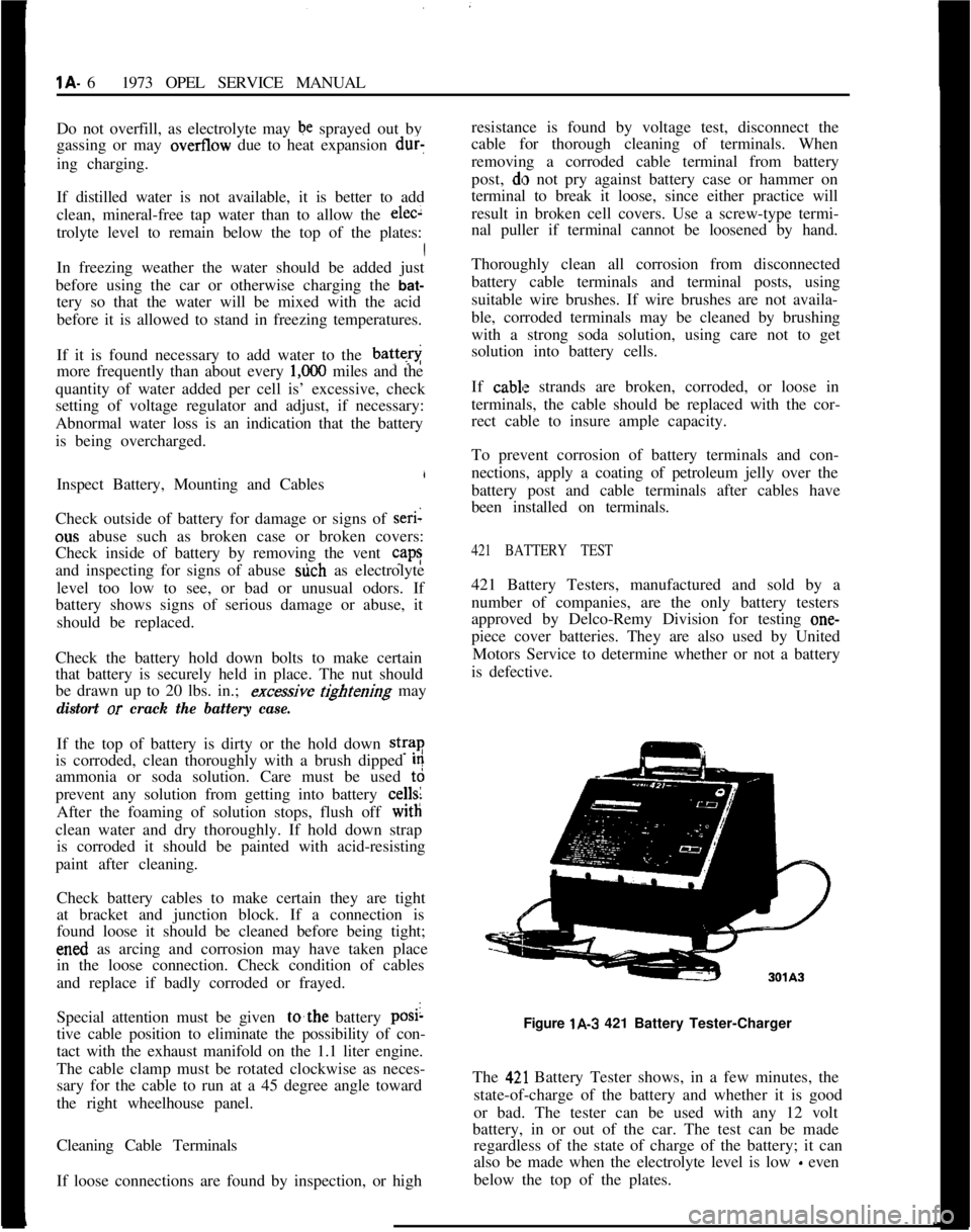
421 BATTERY TEST421 Battery Testers, manufactured and sold by a
number of companies, are the only battery testers
approved by Delco-Remy Division for testing one-
piece cover batteries. They are also used by United
Motors Service to determine whether or not a battery
is defective.
Figure lA-3 421 Battery Tester-Charger
The
42,l Battery Tester shows, in a few minutes, the
state-of-charge of the battery and whether it is good
or bad. The tester can be used with any 12 volt
battery, in or out of the car. The test can be made
regardless of the state of charge of the battery; it can
also be made when the electrolyte level is low
- even
below the top of the plates.
Page 50 of 625

CHARGING SYSTEMlD- 29
REGULAiOR DESCRIPTION
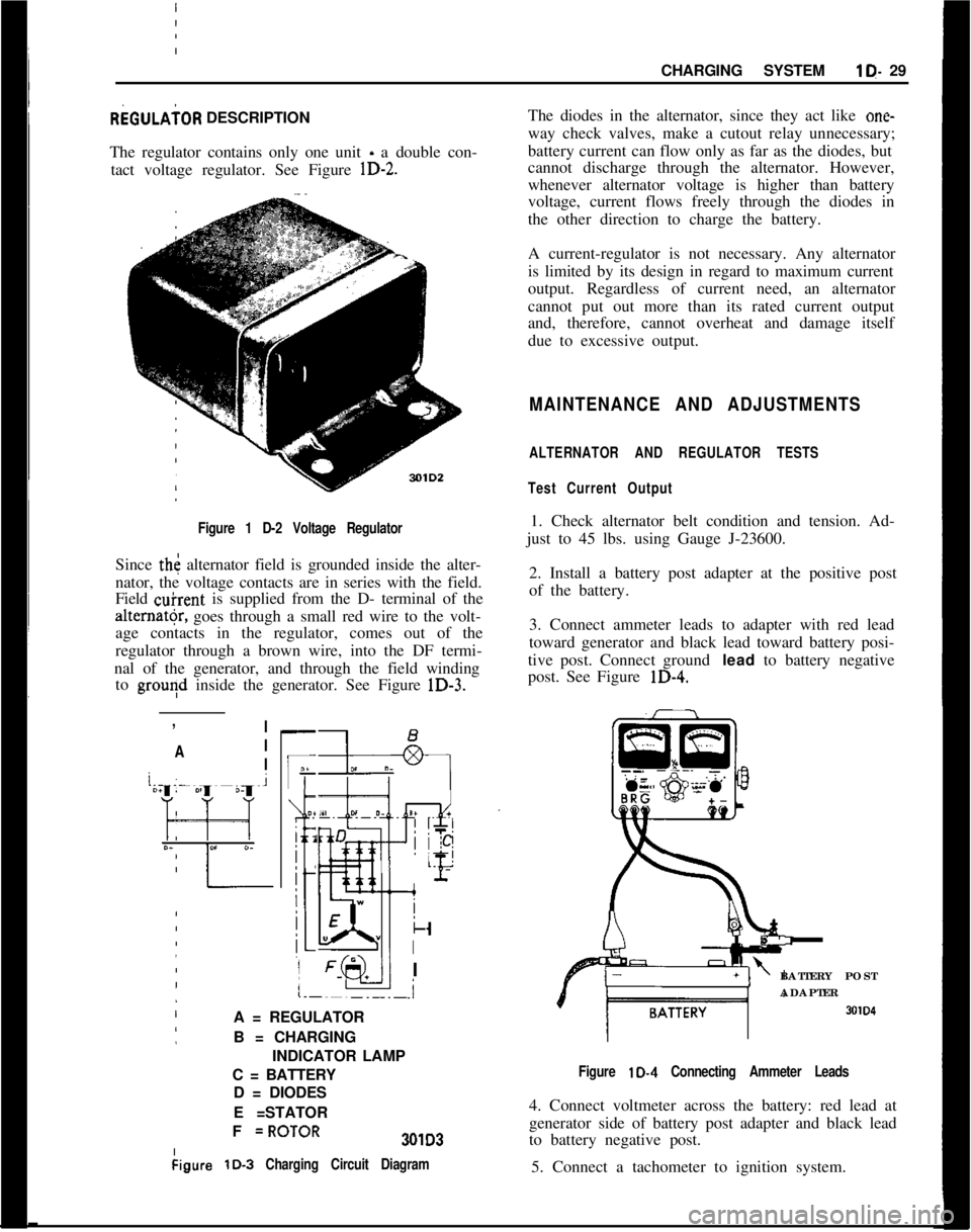
The regulator contains only one unit - a double con-
tact voltage regulator. See Figure
lD-2.
I Figure 1 D-2 Voltage Regulator
Since th< alternator field is grounded inside the alter-
nator, the voltage contacts are in series with the field.
Field
&rent is supplied from the D- terminal of the
alter”@, goes through a small red wire to the volt-
age contacts in the regulator, comes out of the
regulator through a brown wire, into the DF termi-
nal of the generator, and through the field winding to
grouqd inside the generator. See Figure lD-3.
:
,
!
/ I
’ A I
j
/ I
-
IF
O?
i 2
j
:
:
k
I
I
.i
A = REGULATOR
B = CHARGING
INDICATOR LAMP
C = BATTERY D = DIODES
E =STATOR
I
I F
=ROTOR301D3
kigure
lD-3 Charging Circuit Diagram
The diodes in the alternator, since they act like one-
way check valves, make a cutout relay unnecessary;
battery current can flow only as far as the diodes, but
cannot discharge through the alternator. However,
whenever alternator voltage is higher than battery
voltage, current flows freely through the diodes in
the other direction to charge the battery.
A current-regulator is not necessary. Any alternator
is limited by its design in regard to maximum current
output. Regardless of current need, an alternator
cannot put out more than its rated current output
and, therefore, cannot overheat and damage itself
due to excessive output.
MAINTENANCE AND ADJUSTMENTS
ALTERNATOR AND REGULATOR TESTS
Test Current Output
1. Check alternator belt condition and tension. Ad-
just to 45 lbs. using Gauge J-23600.
2. Install a battery post adapter at the positive post
of the battery.
3. Connect ammeter leads to adapter with red lead
toward generator and black lead toward battery posi-
tive post. Connect ground
lead to battery negative
post. See Figure
lD-4.
BATTERY POST
ADAPTER
SOID
Figure lD-4 Connecting Ammeter Leads
4. Connect voltmeter across the battery: red lead at
generator side of battery post adapter and black lead
to battery negative post.
5. Connect a tachometer to ignition system.
Page 65 of 625

1 E- 44 1973 OPEL SERVICE MANUAL)
‘30
1.2.
3.4.
5.
6.
7.
8.
9.
10.
11.
12.
13.
14.
15.ATTACHING SCREWS16. NEGATIVE BRUSH
TRANSMISSION COVER 17. ATTACHING SCREW
HEX. NUT
THREADED END ~18. RETAiNING PLATE
19. POSlilVE BRUSH
PLAY PIN20. WIRE’
GASKET21. THRUST SPRING
BALL22. RUBBFR MOUNTS
DRIVEN GEAR23. ARMATURE
WASHER24. ATTACHING SCREWS
THREADED END25. LOCKWASHER
PLAY PIN26. ANGLE BRACKE’TS
SLEEVE27. MOTOR HOUSING
MOUNTING PLATE28. MAGNET RING
GASKET29. MAGNET THREADED
TOOTHED WASHERSPi N
LOCATORSATTACHING SCREWS30. NORTH POLE PAINT
TRANSMISSIONMARKING ON
HOUSING
THISfSIDENOTE: MOTOR HOUSING
WITH MAGNET RING HAS
TO BE INSTALLED SO THAT
THE NORTH POLE MARKING
(PAINT DOT ON MAGNET
RING) FACES TOWARDS
‘IRANSMISSION.
301 E20Figure 1620 Wi$er Motor
- Exploded View
Page 67 of 625

1F. 46 1973 OPEL SERVICE MANUAL
’
/
Headlight High-Low Beam Control and Passing:
SignalI
When the headlights have been switched on, high
and low beam selection is made by raising the direc-
tional signal lever toward steering wheel. Each
ti&the lever is raised, beam position, will change.
When the headlights are not on, a flashing headlight
signal may be given by raising and lotiering the di-
rectional signal lever. With the headlights on and
inlow beam position, raising and lowering the direc-
tional signal lever will also cause the headlights to
flash.
Fog Light SwitchAll Rallye models are equipped with two white f?g
lights mounted below the front bumper.
The fog light toggle switch is located on the
insty-ment cluster to the left of the temperature and
fuelgauge cluster.
/
The fog lights can be turned off at any time by the
toggle switch, but can only be tyrned on when: :
1. The ignition switch on or the
?gine running.!
2. The fog light toggle switch lower half is pushed
in.3. The parking lights and/or low beam headlights
are
OKThe fog lights are automatically turned off if the
ignition switch is on and the headlights are switched
to high beam position.
Courtesy LightThe courtesy light illuminates the interior of the Car
when any door is opened. The courtesy light can also
be turned on with all doors closed by tilting the l&s.
GT Headlamp MechanismThe concealed headlamps are moved mechanically.
Pushing actuating lever on left side of console opens
headlamps and pulling lever closes headlamps. Two
(2) meshing gear segments convert the movement, of
the lever to a rotation of 180 degrees. The pivots of
the headlamps lie below the centerline so that with
headlamps in closed position, the headlamp housing
is flush with front sheet metal. Refer to Group 110,
Section “F”, for service procedures on the GT head-
lamp mechanism.
A white indicator lamp in the instrument panel lights
if the headlamps are not completely opened lorclosed The switches of the headlamp electrical sys-
tem are located behind the left headlamp operating,
mechanism.
MAINTENANCE AND ADJUSTMENTSHEADLAMP AIMING
The headlamps must be properly aimed in order to
obtain maximum road illumination and safety that
has been built into the headlighting equipment. With
the Guide T-3 type sealed beam units, proper aiming
is even more important because the increased range
and power of this lamp make even slight variations
from recommended aiming hazardous to approach-
ing motorists. The headlamps must be checked for
proper aim whenever a sealed beam unit is replaced
and after an adjustment or repairs of the front end
sheet metal assembly.
Regardless of method used for checking headlamp
aim, car must be at normal weight, that is, with gas,
oil, water, and spare tire. Tires must be uniformly
inflated to specified pressure. If car will regularly
carry an unusual load in rear compartment, or a
trailer, these loads should be on car when headlamps
are checked. Some States have special requirements
for headlamp aiming adjustment, and these require-
ments should be known and observed.
Horizontal and vertical aiming of each seal beam
unit is provided by two adjusting screws which move
the mounting ring in the body against the tension of
the coil spring. There is no adjustment for focus,
since the sealed beam unit is set for proper focus
during manufacturing assembly.
MAJOR REPAIRHEADLIGHT SWITCH
- OPEL 1900. MANTA
Removal1. Remove instrument cluster cover panel. See Sec-
tion H.
2. Compress retaining springs and pull switch out.
See Figure 1 F-
1.3. Pull multiple socket off switch.
Installation
1: Plug multiple socket in switch and push switch in
panel until clips lock in place.
2. Replace instrument cover and secure with two (2)
screws.
Page 75 of 625

lG- 54 1973 OPEL SERVICE’ MANtiAL/SIGNAL SYSTEMSCdNTENTS
9Subject
DESCRIPTION AND OPERAT!ON:
Directional Signal Lever
. . . . . . . . . . . . . . . . . . . . . . . . . . . . . . . . . . . . . . . . . . . . . . . . . .
Horn. . . . . . . . . . . . . . . . . . . . . . . . . . . . . . . . . . . . . . . . . . . . . . . . . . . . . . . . . . . . . . . . . . . . . . . . . . . . . . . . . . . . . . . .HazardWarning
Flasher. . . . . . . . . . . . . . . . . . . . . . . . . . . . . . . . . . . . . . . . . . . . . . . .BrakeSystemWarningLight
. . . . . . . . . . . . . . . . . . . . . . . . . . . . . . . . . . . . . . . .DIAGNOSIS:
SignalSystem,.......................
i . . . . . . . . . . . . . . . . . . . . . . . . . . . . . . . . . . . . . . . . . . . . .MAINTENANCE AND ADJUS,TMENTS:
MAJOR REPAIR:
Directional Signal Switch
:. . . . . . . . . . . . . . . . . . . . . . . . . . . . . . . . . . . . . . . . . . . . .
HornRemoval. . . . . . . . . . . . . . . . . . . . . . . . . . . . . . . . . . . . . . . . . . . . . . . . . . . . . . . . . . . . . . . . . . . . . .Removing Horn Contact
. . . . :.............................................
SPECIFICATIONS:
FuseChart. . . . . . I . . . . . . . . . . . . . . . . . . . . . . . . . . . . . . . . . . . . . . . . . . . . . . . . . . . . . . . . . . . . . . . . . . . . .Page No.
1 G-54
1 G-54
1 G-55
lG-55 _1 G-55
1 G-55
16-551 G-55
1 G-56
DESCRIPTION AND OPERATION
DIRECTIONAL SIGNAL LEVERThe direction signal switch lever is a multi- purpose
lever controlling direction signals, passing signal,
and high and low beams. See Figure
lG-1.301Gl
Figure lG-1 Directional Signal Position for Headlamp
OperationThe direction signal lever is provided with a
two-step mechanism for operation of headlight high and
low beams, and passing signal (not in New Jersey).
With headlights off, moving the lever repeatedly to-
wards steering wheel flashes headlights as a passing
signal. With headlights on, moving the lever repeat-
edly towards steering wheel up to first stop also
flashes passing signal regardless whether or not the
direcl:ion signals are switched on. When the lever is
moved up to the second stop, the headlights are
changed from high to low beam
dr vice versa. On all
Rallye cars, when switching from low to high beam
position, with the fog lamp instrument panel switch
“ON” and ignition switch in “RUN” position, the
fog lights are automatically
switChed off. Direction
signals work in the normal manner; pushing the lever
up for right turn signal and pulling the lever down
for left turn signal.
The horn button is located in the center part of the
steering wheel. The horn is actuated by pushing
down on the ends of both spokes on Opel 1900 andManta’s or on the center horn button on the Rallye.
The button is provided with a spring-loaded plunger.See Figure
lG-2.
Page 81 of 625

/
I1 H- 601973 OPEL SEW& MANUAL
1. Remove headlight switch button by depressing
retaining clip on shaft and pulling back on switch
knob. See Figure lH-3.
Figure 1 H-5
- Removing Cluster Screws
Figure lH-3
- Removing Headlight Switch Knob,
2. Remove two (2) plugs on cluster panel. See FigurelH-4.301H6
-Figure 1 H-4 Removing Plugs
3. Remove two (2) sheet metal screws behind plugs
on cluster. See Figure lH-5.
4. Pull off heater control knobs toward front.
j5. On top, carefully pull instrument ‘trim plate
:to-wards steering wheel and remove plate.
6. Remove two screws for lower housing
attach&t.See Figure lH-6.Figure 1 H-6 Lower Housing Attaching Screws
7. Disconnect speed0 cable at cluster by turning cou-
pling counterclockwise.
8. If equipped, pull heated rear window or fog lamp
switch out of instrument housing and disconnect
wires from switches.
9. Pull cluster right and left sides partially out and
disconnect wires on back of cluster. See Figure lH-7.
Installation
1.
P&e instrument cluster in position and connect
wires on back of cluster.
2. Pull fog light or heated back glass switch wires
into opening, if equipped, and connect wires and
replace switch.
3. Connect two screws on lower housing attachment.
Page 127 of 625

fabric to dry thoroughly; then rub lightly with a
clean cloth dipped in a volatile cleaner. This is the
only further treatment recommended.
Soap and water are not recommended since they will
probably set the stain and cause a permanent dis-
coloration. Drying the fabric by means of heat (such
as the use of an iron) is not recommended.
6. Grease and 02 If grease has been spilled on the
material, as much as possible should be remove by
scraping with a dull knife or spatula before further
treatment is attempted.
Grease and oil stains may be removed by rubbing
lightly with a clean cloth saturated with a volatile
cleaner. Be sure all motions are toward the center of
the stained area to decrease the possibility of spread-
ing the stain.
7. Ice Cream. The same procedure is recommended
for the removal of ice cream stains as that used in
removing fruit stains.
If the stain is persistent, rubbing the spot with a cloth
wet with soap suds (mild neutral soap) may be used
to some advantage after the initial treatment with hot
water. This soap treatment should be followed with
a rinsing, by rubbing with a clean cloth wet with cold
water. After this dries, rubbing lightly with a cloth
wet with volatile cleaner will clear up the last of the
stain, by removing fatty or oily matter.
8.Vomit. Sponge with a clean cloth, dipped in clear
cold water. After most of the stain has been removed
in this way wash lightly with soap (mild neutral),
using a clean cloth and lukewarm water. Then rub
with another clean cloth dipped in cold water. If any
of the stain remains after this treatment, gently rub
clean with a cloth moistened with a volatile cleaner.
SPECIFICATIONS
BOLT TORQUE SPECIFICATIONSLocation
DoorStriker toPillarPostr .^ ...r.ZA- 41973 OPEL SERVICE MANUAL
9. Shoe Polish and Dressings. On types of shoe
dressing which contain starch or dextrine or some
water soluble vehicle, allow the polish to dry; then
brush the spot vigorously with a brush. This will
probably be all the treatment that is necessary. If
further treatment is required moisten the spot with
cold water and after it has dried, repeat the brushing
operation.
Paste or wax type shoe polishes may require using a
volatile cleaner. Rub the stain gently with a cloth wet
with a volatile cleaner until the polish is removed.
Use
;a clean portion of the cloth for each rubbing
operation and rub the stained area from outside to
center.
10. Tar. Moisten the spot lightly with a volatile
cleaner, and then remove as much of the tar as possi-
ble with a dull knife. Follow this operation by rub-
bing the spot lightly with a cloth wet with the cleaner
until the stain is removed.
II. .X&e. Sponge the stain with a clean cloth satu-
rated with soap suds (mild neutral soap) and rinse
well by rubbing the stain with a clean cloth dipped
in cold water. Then saturate a clean cloth with a
solution of one part household ammonia water and
five parts water. Apply the cloth to the stain and
allow solution to remain on affected area for one
minute; then rinse by rubbing with a clean wet cloth.
I,?.
L,ipslick. The compositions of different brands of
lipsticks vary, making the stains very
diff%cult to
remove. In some instances a volatile cleaner may
remove the stain. If some stain remains after re-
peated applications of the volatile cleaner, it is best
to leave it rather thari try other measures.
Torque
Lb.Ft.
wont saar twacnment to war........................................Seat andShoulderBelt Anchor Attachment
................StationwagonTailgate
HingetoBody............................StationwagonTailgate
HingetoDoor............................Stationwagon Striker Plate on
Body................................Stationwagon
LatchHookonBody..................................Stationwagon Latch on Door
............................................14.18
_^ _^13-1036-46
13-16
13-16
3-4
13-16
3-4
Page 136 of 625

DOORS
CONTENTS
Subject
DESCRIPTION AND OPERATION: (Not Applicable)
DIAGNOSIS: (Not Applicable)
MAINTENANCE AND ADJUSTMENTS: (Not
Applicable)
MAJOR REPAIR:
Front Door - Removal and Installation
DoorLockStriker..........................................................
WindowRegulator
Handle..........................................
Trim
Pad............................................................................
DoorHandle.Inside......................................................
RevealMolding................................................................
WindowLifter..................................................................
DoorLockCylinder........................................................
Weatherstrip....................................................................
Door....................................................................................
Rear Door
- Removal and Installation
SashWindow..................................................................
Window Regulator........................................................
TailGate............................................................................
Door....................................................................................
SPECIFICATIONS:Page No.
2D-13
2D-13
2D-13
2D-15
2D-1520-l
5
2D-17
2D-10
20-18
2D-19
2D-20
2D-21
2D-21
MAJOR REPAIRREMOVAL AND INSTALLATION OF DOOR LOCK
STRIKER1. Mark position of old striker on lock pillar and
unscrew striker, using Tool J-23659. See Figure
2D-2.2. Place new striker in installation position and tem-
porarily tighten striker, observing marking on lock
pillar. Close door and check whether this can be
done without exerting any force. If this is not the
case, adjust striker accordingly.
3. Tighten attaching screws, using Tool J-23659, and
check for proper operation.REMOVAL AND INSTALLATION OF WINDOW
REGULATOR HANDLE1. Insert Tool J-7797 between handle and nylon disc.
See Figure
2D-3.2. With the two fork-shaped ends of the tool, slide
lock spring outwards. See Figure
2D-4.3. Place lock spring of new handle in installation
position and install it onto window regulator shaft.
4. With the window in closed position, the window
regulator handle should point upwards towards the
front at an angle of approximately 45 degrees.
REMOVAL AND INSTALLATION OF FRONT
DOORTRIM PAD
1. Remove window regulator handle.
Page 138 of 625

dOORS2D-15
3. Unhook con&cting rod out of old support and
hook into new support and door lock.
the water deflector foil is inserted in lower door slot.See Figure
2D-6. Reverse procedure for installation.2D-i-
Figure
2D-7 Removing Support
4. Screw support onto door inner panel so that it canbe shifted in both holes. Adjust remote control so
that the connecting rod has a clearance at the door
lock of
.02 inch (0.5 mm).
5. Tighten support to door inner panel.
b. Install door trim pad
REMOVAL AND INSTALLATION OF FRONT
DOOR
BELT REVEAL MOLDING
1. Bend up ends of molding.2. With a wooden wedge, pry off molding towards
the top. See Figure
2D-8.Figure
2D-6 Installing Water Deflector
REMOVAL AND INSTALLATION OF FRONT
DOOR
INSIDEHANDLE WITH SUPPORT
1. Remove door trim pad.
2. Unscrew support and unhook connecting rod out
of door lock. See Figure
2D-7.Figure
2D-6 Removing Molding
3. Check retaining clamps in outer door panel for
proper position and tight seat. Push new molding
onto retaining clamps and bend both ends inwards.
REMOVAL AND INSTALLATION OF FRONT
DOOR
WINDOW LIFTER
Removal1. Remove door trim pad.
Page 143 of 625

2D-201973 OPEL SERVICE MANUAL
2. Remove door sash window.
Figure 2D-23 Guide Rail Screws
3. Pull guide rail towards the top out of door.
4. Position sash window so that cable retainer can be
unscrewed through access hole. Pull out sash win-
dow towards the top.
5. Push sash channel off window glass. See Figure2D- 24.Figure 2D-25 Cable and Pully Location
3. Loosen sheave adjustable bracket. Unscrew win-
dow regulator from inner door panel and remove
regulator and cable through access hole. See Figure
2D-26.Figure 2D-24 Sash Channel
6. Place new window glass and new filler into sash
channel.
REMOVAL AND INSTALLATION OF REAR
DOOR WINDOW REGULATOR
1. Remove door trim pad.Figure
213-26 Regulator Attaching Screws
Installation
- Left Door
In counterclockwise direction, wind cable onto pul-
ley up to the shoulder and clamp it behind lug. See
Figure 2D-27.