wheel bolts OPEL GT-R 1973 Owner's Manual
[x] Cancel search | Manufacturer: OPEL, Model Year: 1973, Model line: GT-R, Model: OPEL GT-R 1973Pages: 625, PDF Size: 17.22 MB
Page 212 of 625

GT STEERING COLUMN ASSEMBLY3E- 45
loose must never be done. The only recommendation
for freeing frozen steering wheels is to use a penetrat-
ing lubricant.Installation1. Before installing steering wheel, lubricate return
pin and slide area on direction signal switch return
cams and horn ring contact.
2. With steering wheel properly aligned to shaft, in-
stall lockplate and nut. Torque nut to 15
Ib.ft.
CAUTION:
This steering wheel to steering shafi fas-
tener is an important attac&ng part in that it could
affect the performance of vital components and sys-
tems, and/or could result in major repair expense. It
must be
rep/aced with one of the same part number
or with an equivalent part, if replacement becomes
necessary. Do not use a replacement part of lesser
quality or substitute design. Torque values must be
used as specified during reassembly to assure proper
retention of this part.3. Bend up lockplate tab and install horn cap.
4. Reconnect battery.
REMOVAL AND INSTALLATION OF IGNITION
LOCK CYLINDER
RemovalThis procedure may be performed with the steering
column assembly either removed or installed in the
car.1. Remove steering wheel, as outlined previously in
this Group.
2. Position lock cylinder to run position.
3. Using suitable piece of wire, push in lock cylinder
retaining pin and remove lock cylinder. See Figure3E- 18.
Installation1. Insert lock cylinder into lock cylinder housing.
2. Install steering wheel, as outlined previously in
this section.
REMOVAL AND INSTALLATION OF STEERING
COLUMN ASSEMBLY
Removal1. Position steering so that front wheels are straight
ahead.Figure
3E-18 Removing Lock Cylinder
2. Loosen steering shaft upper universal joint lower
clamp bolt. See Figure
3E-19.3. Drill off heads of both tear bolts by first drilling
an 3/16 inch pilot hole and then inserting a
l/4 inch
bolt extractor to remove lockbolt.
4. Disconnect ignition (white) and direction signal
(black) wire set plugs.
5. Support steering column assembly and remove
both hex. head bolts.
6. Pull steering column assembly off center steering
shaft. Do not apply any force as plastic injections in
center steering shaft may be loosened and shaft
would then require replacement.
Installation
CAUTION:
Fasteners are important attachingparts in
that they
cooId affect the performance of vital com-
ponents and systems, and/or could result in major
repair expense. They must be replaced with one of
the same part number or with an equivalent part if
replacement becomes necessary. Do not use a re-
placement part of lesser quality or
substitute design.
Torque values must be used as specified during
reas-
sembIy to assure proper retention of these parts.1. Install steering column assembly onto steering
shaft and torque steering shaft upper universal joint
lower clamp bolt to 14
lb.ft.2. Install hex head bolts and torque to 14
lb.ft.
NOTE:
Be sure to install ground wire.
Page 213 of 625

I3E. 461973 OPEL SERVICE MANUAL
Figure 3E-19 Steering Column Attachments
3. Install new tear bolts and tighten until hex
head of bolt is tom off.
4. Reconnect ignition and direction signal wire sets.
REMOVAL AND INSTALLATION OF CENTER
STEERING SHAFT
RemovalSteering shaft must be handled carefully so as not to
loosen plastic injections as shaft would then require
replacement.
CAUTION:Fasteners are important attaching parts
in that they could affect the performance of vital
components and systems, and/or could result in
major repair expense. They must be replaced with
one of the same part number or with an
equivalent part if replacement becomes necessary.
Do not use a replacement part or lesser quality or
substitute design. Torque values must be used as
specitied during reassembIy to assure proper
retention of these parts.1. Install steering shaft through bottom and position
into upper universal joint.
1. Position steering so that front wheels are straight
ahead.2. Insert shaft into lower universal joint and torque
bolt to 22 lb.ft.
2. Loosen steering shaft upper universal joint lower
clamp bolt.3. Torque upper universal joint bolt to 14
lb.ft.3. Remove steering shaft lower universal joint upper
clamp screw.
4. Carefully push center steering shaft up into steel
washer joint until lower end is free.REMOVAL AND INSTALLATION OF IGNITION
SWITCH AND/OR STEERING LOCK
Removal5. Remove steering shaft through bottom.
1, Remove ignition lock cylinder, see previous para-
graph in this section.
Page 219 of 625
3F. 521973 OPEL SERVICE MANUAL
3. Install rubber grommet, retainer and self-locking
nut at top of shock absorber. Torque to 10 lb. ft.
Always use new self-locking nuts.
REAR SPRING REMOVAL AND INSTALLATION
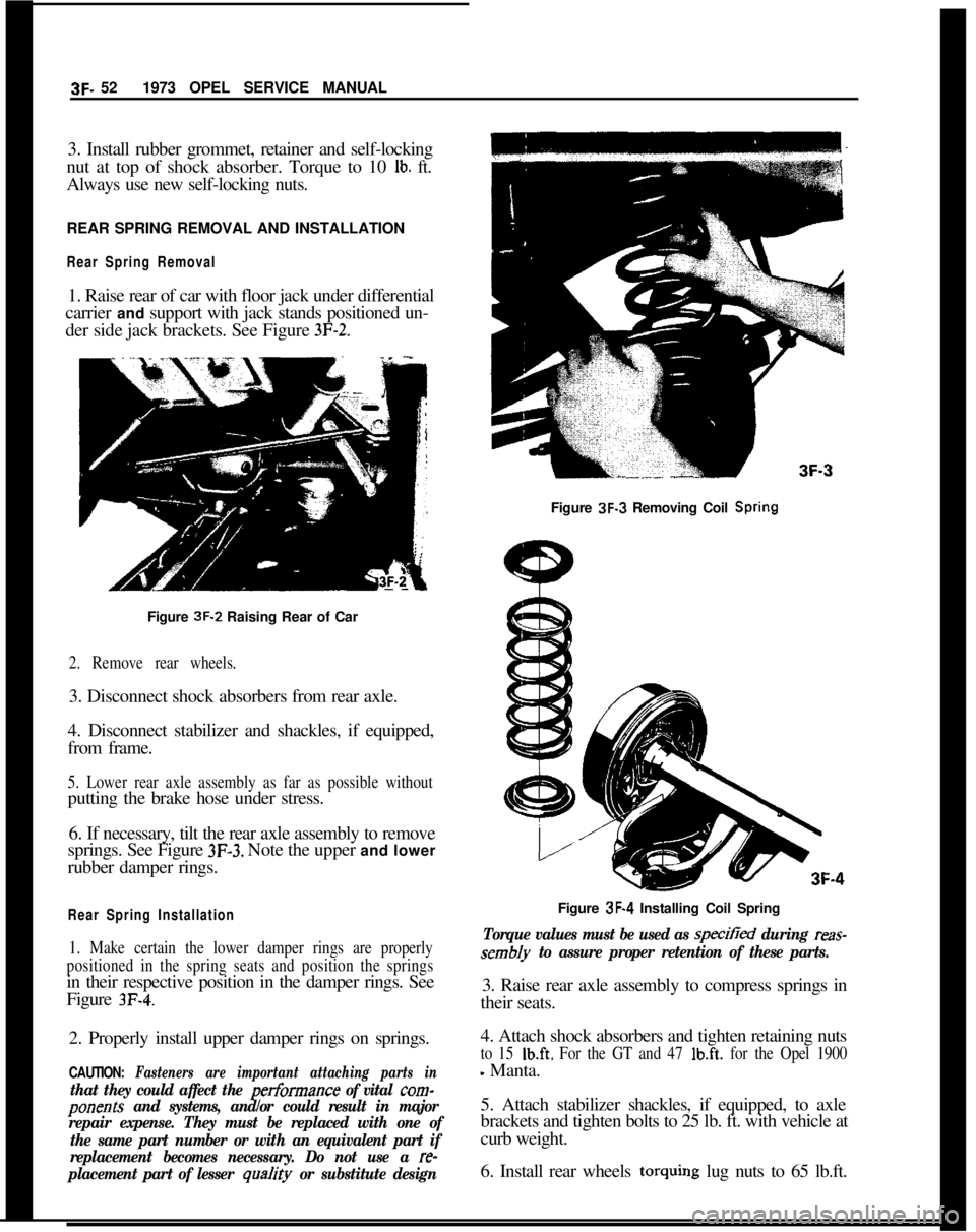
Rear Spring Removal1. Raise rear of car with floor jack under differential
carrier and support with jack stands positioned un-
der side jack brackets. See Figure
3F-2.Figure 3F-3 Removing Coil
SpringFigure 3F-2 Raising Rear of Car
2. Remove rear wheels.3. Disconnect shock absorbers from rear axle.
4. Disconnect stabilizer and shackles, if equipped,
from frame.
5. Lower rear axle assembly as far as possible withoutputting the brake hose under stress.
6. If necessary, tilt the rear axle assembly to remove
springs. See Figure
3F-3. Note the upper and lower
rubber damper rings.
Rear Spring Installation
1. Make certain the lower damper rings are properly
positioned in the spring seats and position the springsin their respective position in the damper rings. See
Figure
3F-4.2. Properly install upper damper rings on springs.
CAUTION: Fasteners are important attaching parts in
that they could affect the performance of vital corn-
ponents and systems, and/or could result in major
repair expense. They must be replaced with one of
the same part number or with an equivalent part if
replacement becomes necessary. Do not use a
re-
placement part of lesser
qua/ity or substitute designFigure 3F-4 Installing Coil Spring
Torque values must be used as specitied during reas-
sembly to assure proper retention of these parts.3. Raise rear axle assembly to compress springs in
their seats.
4. Attach shock absorbers and tighten retaining nuts
to 15 Ib.ft. For the GT and 47 lb.ft. for the Opel 1900
- Manta.
5. Attach stabilizer shackles, if equipped, to axle
brackets and tighten bolts to 25 lb. ft. with vehicle at
curb weight.
6. Install rear wheels torquing lug nuts to 65 lb.ft.
Page 220 of 625

REAR SUSPENSION3F- 53
7. Remove jack stands.
LOWER CONTROL ARM REPLACEMENTRemovalThis operation can be performed with the vehicle
standing at curb height or elevated.
1. Disconnect parking brake cable from support
bracket on control arm.
2. Loosen and remove front and rear control arm
attaching bolts and remove control arm.
installation1. On
1900’s and Manta’s place a load of approxi-
mately 350 lbs. in luggage compartment or on the
GT, place a load of approximately 150
Ibs. on dri-
ver’s seat. Torque control arm attaching nut and
bolts to 18 lb.ft on
GT’s and 23 Ib.ft. on the 1900 -Manta.
2. Connect parking brake cable to support bracket on
control
ranI.
STABILIZER ROD REPLACEMENT
Removal1. Raise and support rear of vehicle.
2. Disconnect stabilizer rod to shackle bolts.
3. Disconnect stabilizer rod to underbody retainers
and work stabilizer rod out from under vehicle.
SPECIFICATIONS
REAR SUSPENSION SPECIFICATIONS
Tightening SpecificationsInstallation1. Work stabilizer rod into position and loosely at-
tach stabilizer to underbody retainers.
2. Connect stabilizer rod to shackles.
3. With the vehicle standing on its wheels or the rear
axle assembly lifted, tighten stabilizer rod to under-
body bracket bolts to 15 lb. ft.
4. Remove jack stands and lower vehicle.
TRACK ROD REPLACEMENT
Removal1. Lift rear of car and suitably support.
2. Disconnect track rod from rear axle and frame
side member.
Installation
1. Loosely connect track rod first to side member and
then to the rear axle.
2. On the
1900 - Manta, load luggage compartment
of vehicle with approximately 350 lbs. or on the GT,
place a load of approximately 150 lbs. on driver’s
seat and tighten track rod attaching bolts to specified
torque.
3. Remove supports (jack stands) and lower vehicle.
Use a reliable torque wrench. Specifications are for clean and lightly-oiled
threads.
Part
Nut
Nut
Nut
Bolt
Nut
Nut
Nut
BoltName
WheelNuts.
.._.._......._........................................................
Control Arm Attaching (GT) .._.._.,,,........,,.,,.......,,......,,,,......
Control Arm Attaching (1 900 - Manta) .,,...._...,,,,_.....,,.,...
Stabilizer Rod to Underbody Retainers ,....._.,.,,.,.....,,,....
Shock Absorber Lower Attachment (GT) . .._.....,._.._.,,,...
Shock Absorber Lower Attachment (1900 Manta) ,,.,
Shock Absorber Upper Attachment. .._.....................
Stabilizer Shackle to Axle Bracket .._._.._,...._..,,.,,.......,,,...
Torque
Lb.Ft.
65
16
23
15
1,5
47
1025
Page 240 of 625
REAR AXLE48. 9
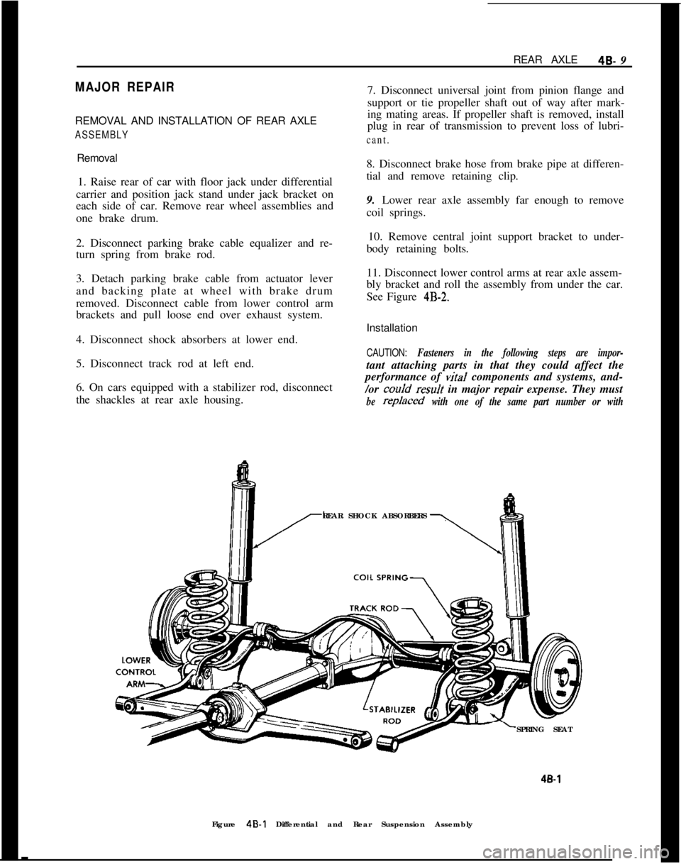
MAJOR REPAIRREMOVAL AND INSTALLATION OF REAR AXLE
ASSEMBLYRemoval
1. Raise rear of car with floor jack under differential
carrier and position jack stand under jack bracket on
each side of car. Remove rear wheel assemblies and
one brake drum.
2. Disconnect parking brake cable equalizer and re-
turn spring from brake rod.
3. Detach parking brake cable from actuator lever
and backing plate at wheel with brake drum
removed. Disconnect cable from lower control arm
brackets and pull loose end over exhaust system.
4. Disconnect shock absorbers at lower end.
5. Disconnect track rod at left end.
6. On cars equipped with a stabilizer rod, disconnect
the shackles at rear axle housing.7. Disconnect universal joint from pinion flange and
support or tie propeller shaft out of way after mark-
ing mating areas. If propeller shaft is removed, install
plug in rear of transmission to prevent loss of lubri-cant.8. Disconnect brake hose from brake pipe at differen-
tial and remove retaining clip.
9. Lower rear axle assembly far enough to remove
coil springs.
10. Remove central joint support bracket to under-
body retaining bolts.
11. Disconnect lower control arms at rear axle assem-
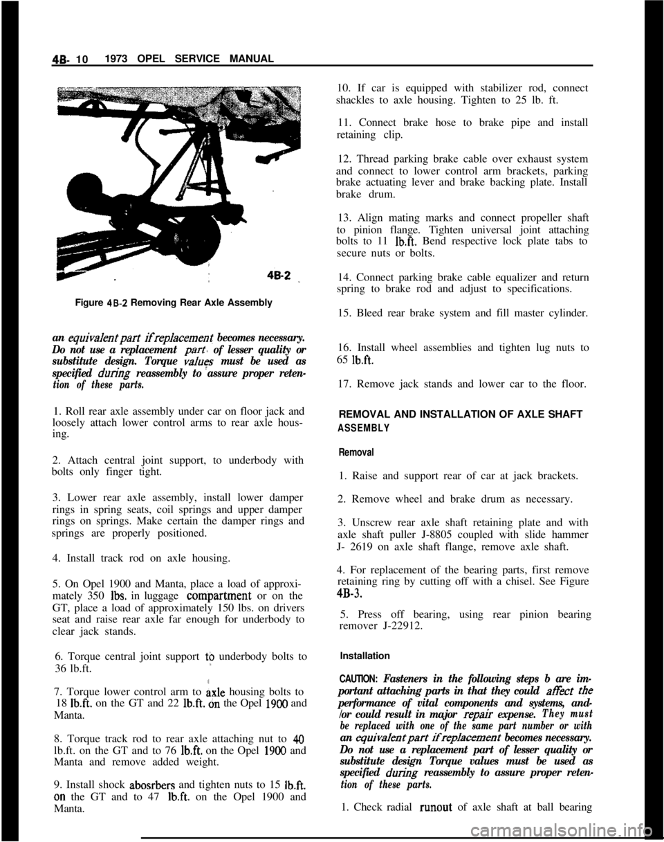
bly bracket and roll the assembly from under the car.
See Figure
4B-2.Installation
CAUTION: Fasteners in the following steps are impor-tant attaching parts in that they could affect the
performance of vital components and systems, and-
/or coo/d
resuJt in major repair expense. They must
be rep/aced with one of the same part number or withREAR SHOCK ABSORBERS
SPRING SEAT
4B-1Figure
4B-l Differential and Rear Suspension Assembly
Page 241 of 625
4B- 101973 OPEL SERVICE MANUAL
Figure 48-Z Removing Rear Axle Assemblyan equiva/entpart ifreplacement becomes necessary.
Do not use a replacement
part of lesser quality or
substitute design. Torque
values must be used as
specified
during reassembly to assure proper reten-
tion of these parts.1. Roll rear axle assembly under car on floor jack and
loosely attach lower control arms to rear axle hous-
ing.
2. Attach central joint support, to underbody with
bolts only finger tight.
3. Lower rear axle assembly, install lower damper
rings in spring seats, coil springs and upper damper
rings on springs. Make certain the damper rings and
springs are properly positioned.
4. Install track rod on axle housing.
5. On Opel 1900 and Manta, place a load of approxi-
mately 350
Ibs. in luggage conipartment or on the
GT, place a load of approximately 150 lbs. on drivers
seat and raise rear axle far enough for underbody to
clear jack stands.
6. Torque central joint support t$ underbody bolts to
36 lb.ft.
7. Torque lower control arm to
Axle housing bolts to
18
Ib.ft. on the GT and 22 lb.ft. dn the Opel 1900 and
Manta.
8. Torque track rod to rear axle attaching nut to
40lb.ft. on the GT and to 76
lb.ft. on the Opel 1900 and
Manta and remove added weight.
9. Install shock abosrbers and tighten nuts to 15
Ib.ft.on the GT and to 47
Ib.ft. on the Opel 1900 and
Manta.10. If car is equipped with stabilizer rod, connect
shackles to axle housing. Tighten to 25 lb. ft.
11. Connect brake hose to brake pipe and install
retaining clip.
12. Thread parking brake cable over exhaust system
and connect to lower control arm brackets, parking
brake actuating lever and brake backing plate. Install
brake drum.
13. Align mating marks and connect propeller shaft
to pinion flange. Tighten universal joint attaching
bolts to 11
Ib.ft. Bend respective lock plate tabs to
secure nuts or bolts.
14. Connect parking brake cable equalizer and return
spring to brake rod and adjust to specifications.
15. Bleed rear brake system and fill master cylinder.
16. Install wheel assemblies and tighten lug nuts to
65
lb.ft.17. Remove jack stands and lower car to the floor.
REMOVAL AND INSTALLATION OF AXLE SHAFT
ASSEMBLY
Removal1. Raise and support rear of car at jack brackets.
2. Remove wheel and brake drum as necessary.
3. Unscrew rear axle shaft retaining plate and with
axle shaft puller J-8805 coupled with slide hammer
J- 2619 on axle shaft flange, remove axle shaft.
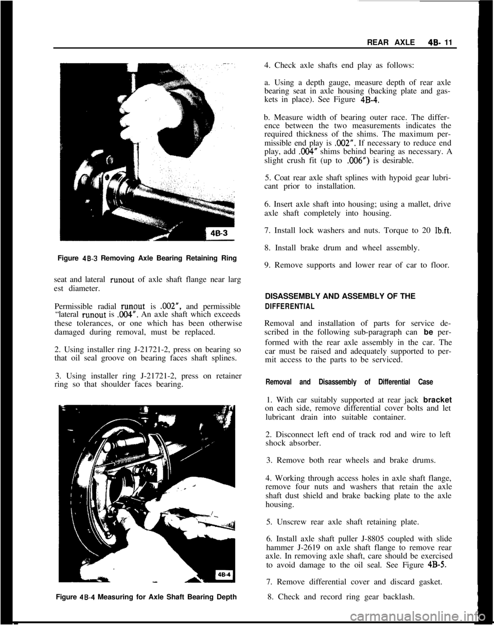
4. For replacement of the bearing parts, first remove
retaining ring by cutting off with a chisel. See Figure4B-3.
5. Press off bearing, using rear pinion bearing
remover J-22912.
Installation
CAUTION: Fasteners in the following steps b are im-
portant attaching parts in that they could at&t
tee
performance of vital components and systems, and-
/or could result in major
repair expense.They must
be replaced with one of the same part number or with
an equivalentpart ifreplacement becomes necessary.
Do not use a replacement part of lesser quality or
substitute design Torque values must be used as
specified
during reassembly to assure proper reten-
tion of these parts.1. Check radial runout of axle shaft at ball bearing
Page 242 of 625
REAR AXLE40- 11
Figure
48-3 Removing Axle Bearing Retaining Ring
seat and lateral runout of axle shaft flange near larg
est diameter.
Permissible radial runout is .002”, and permissible
“lateral runout is
.OO4”. An axle shaft which exceeds
these tolerances, or one which has been otherwise
damaged during removal, must be replaced.
2. Using installer ring J-21721-2, press on bearing so
that oil seal groove on bearing faces shaft splines.
3. Using installer ring J-21721-2, press on retainer
ring so that shoulder faces bearing.
Figure 48.4 Measuring for Axle Shaft Bearing Depth4. Check axle shafts end play as follows:
a. Using a depth gauge, measure depth of rear axle
bearing seat in axle housing (backing plate and gas-
kets in place). See Figure
4B-4.b. Measure width of bearing outer race. The differ-
ence between the two measurements indicates the
required thickness of the shims. The maximum per-
missible end play is .002”. If necessary to reduce end
play, add
,004” shims behind bearing as necessary. A
slight crush fit (up to ,006”) is desirable.
5. Coat rear axle shaft splines with hypoid gear lubri-
cant prior to installation.
6. Insert axle shaft into housing; using a mallet, drive
axle shaft completely into housing.
7. Install lock washers and nuts. Torque to 20
Ib.ft.8. Install brake drum and wheel assembly.
9. Remove supports and lower rear of car to floor.
DISASSEMBLY AND ASSEMBLY OF THE
DIFFERENTIALRemoval and installation of parts for service de-
scribed in the following sub-paragraph can be per-
formed with the rear axle assembly in the car. The
car must be raised and adequately supported to per-
mit access to the parts to be serviced.
Removal and Disassembly of Differential Case1. With car suitably supported at rear jack bracket
on each side, remove differential cover bolts and let
lubricant drain into suitable container.
2. Disconnect left end of track rod and wire to left
shock absorber.
3. Remove both rear wheels and brake drums.
4. Working through access holes in axle shaft flange,
remove four nuts and washers that retain the axle
shaft dust shield and brake backing plate to the axle
housing.
5. Unscrew rear axle shaft retaining plate.
6. Install axle shaft puller J-8805 coupled with slide
hammer J-2619 on axle shaft flange to remove rear
axle. In removing axle shaft, care should be exercised
to avoid damage to the oil seal. See Figure
4B-5.7. Remove differential cover and discard gasket.
8. Check and record ring gear backlash.
Page 269 of 625

5B- 10 1973 OPEL SERVICE MANUAL
DISC BRAKES
CONTENTS
Subject
DESCRIPTION AND OPERATION:
Description. . . . . . . . . . . . . . . . . . . . . . . . . . . . . . . . . . . . . . . . . . . . . . . . . . . . . . . . . . . . . . . . . . . . . . . . . . . .Operation
. . . . . . . . . . . . . . . . . . . . . . . . . . . . . . . . . . . . . . . . . . . . . . . . . . . . . . . . . . . * . . . . . . . . . . . . . . . . . .DIAGNOSIS:
DiscBrakeTroubleDiagnosis. . . . . . . . . . . . . . . . . . . . . . . . . . . . . . . . . . . . . . . .MAINTENANCE AND ADJUSTMENTS:
Disc Brake Maintenance
. . . . . . . . . . . . . . . . . . . . . . . . . . . . . . . . . . . . . . . . . . . . . . . .Checking Disc Brake Friction Pads for Wear
. . . . . . . . . .Replacing Friction Pads
Checking Brake Disc for Lateral
Runout. . . . . . . . . . . . . . . . . .MAJOR REPAIR:
RemovingandInstallingBrakeCaliper. . . . . . . . . . . . . . . . . . . . . .Removing and Installing Brake Disc
. . . . . . . , . . . . . . . . . . . . . . . . . .
RemovingandInstallingBrakeDiscShield. . . . . . . . . . . . . .Disassembly and Assembly of Brake Caliper
. . . . . . . . . .SPECIFICATIONS:
Disc Brake Specifications
. . . . . . . . . . . . . . . . . . . . . . . . . . . . . . . . . . . . . . . . . . . . . .Page No.
58-1058-l
1
58-12
58-15
SB-15
5&17
56-17
58-17
58-195519
58-21
DESCRIPTION AND OPERATION
DESCRIPTIONThe front wheel disc brake consists of two major
parts: The brake disc and the brake caliper with the
two friction pads. See Figure
5B-20.The brake disc is attached to the inside of the wheel
hub flange by four bolts and centered on a shoulder
of the hub. The brake caliper consists of two halves:
the mounting half, arranged on the inside of the
brake disc, and the rim half. The two halves are
firmly attached to each other by four bolts. Two
flanges on the mounting half serve as attachment of
the brake caliper to the steering knuckle. The brake
caliper is positioned behind the front suspension
cross member at steering knuckle spindle level. It is
attached to the steering knuckle by two bolts. Both
caliper halves act as brake cylinders and each houses
a piston and a fluid seal. The fluid seal, of square
cross section, is positioned in an annular groove of
the caliper bore, preventing fluid leakage past the
piston and entry of water and dirt. The pistons and
caliper half bores are protected against entry of waterFigure 58.20 Left Front Disc Brake Assembly
and dirt in brake disc direction by a rubber seal, held
on the caliper half collar by a clamp ring and against
Page 272 of 625
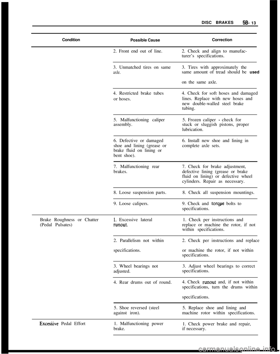
DISC BRAKES5B- 13
Condition
Possible CauseCorrection
2. Front end out of line.2. Check and align to manufac-
turer’s specifications.
3. Unmatched tires on sameaxle.3. Tires with approximately the
same amount of tread should be used
on the same axle.
4. Restricted brake tubes
or hoses.4. Check for soft hoses and damaged
lines. Replace with new hoses and
new double-walled steel brake
tubing.
5. Malfunctioning caliper
assembly.5. Frozen caliper
- check for
stuck or sluggish pistons, proper
lubrication.
6. Defective or damaged
shoe and lining (grease or
brake fluid on lining or
bent shoe).6. Install new shoe and lining in
complete axle sets.
7. Malfunctioning rear
brakes.7. Check for brake adjustment,
defective lining (grease or brake
fluid on lining) or defective wheel
cylinders. Repair as necessary.
8. Loose suspension parts.
9. Loose calipers.8. Check all suspension mountings.
9. Check and torque bolts to
specifications.
Brake Roughness or Chatter
(Pedal Pulsates)
1. Excessive lateralrunout.1. Check per instructions and
replace or machine the rotor, if not
within specifications.
2. Parallelism not within
specifications.2. Check per instructions and replace
or machine the rotor, if not within
specifications.
3. Wheel bearings not
adjusted.3. Adjust wheel bearings to correct
specifications.
4. Rear drums out of round.4. Check runout and, if not within
specifications, turn the drums within
specifications.
5. Shoe reversed (steel
against iron).5. Replace shoe and lining and
machine rotor within specifications.
ExcesGve Pedal Effort1. Malfunctioning power
brake.1. Check power brake and repair,
if necessary.
Page 276 of 625
DISC BRAKES58.17a tine cut file.Do not use any solvent except dena-
tured alcohol. Do not use a
metaIJic scraper too/.8. With a punch, drive one dowel pin from inboard
side through caliper and friction pads to stop. Install
new cross-shaped retaining spring under installed
dowel pin, then install second dowel pin. Loose tit-
ting dowel pins must be replaced.
9. Before operating vehicle, depress brake pedal sev-
eral times to adjust friction pads to brake discs.
Check brake fluid level and add fluid as necessary to
bring level up to “MAX” on reservoir.
Car owners must be informed that a break-in period
exists for new friction pads, and that they must avoid
unnecessary, forceful braking during the first 125
miles after installation of new friction pads.
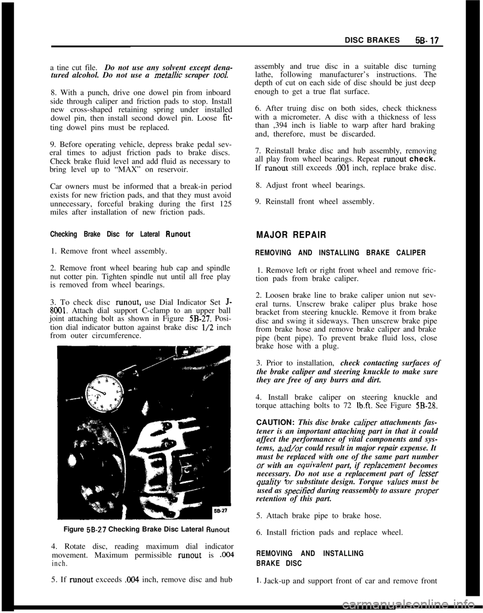
Checking Brake Disc for Lateral Runout1. Remove front wheel assembly.
2. Remove front wheel bearing hub cap and spindle
nut cotter pin. Tighten spindle nut until all free play
is removed from wheel bearings.
3. To check disc runout, use Dial Indicator Set
J-
8001. Attach dial support C-clamp to an upper ball
joint attaching bolt as shown in Figure
5B-27. Posi-
tion dial indicator button against brake disc
l/2 inch
from outer circumference.
Figure 58-27 Checking Brake Disc Lateral
Runout4. Rotate disc, reading maximum dial indicator
movement. Maximum permissible runout is
,004
inch.5. If runout exceeds
0% inch, remove disc and hubassembly and true disc in a suitable disc turning
lathe, following manufacturer’s instructions. The
depth of cut on each side of disc should be just deep
enough to get a true flat surface.
6. After truing disc on both sides, check thickness
with a micrometer. A disc with a thickness of less
than ,394 inch is liable to warp after hard braking
and, therefore, must be discarded.
7. Reinstall brake disc and hub assembly, removing
all play from wheel bearings. Repeat runout check.
If runout still exceeds
,001 inch, replace brake disc.
8. Adjust front wheel bearings.
9. Reinstall front wheel assembly.
MAJOR REPAIR
REMOVING AND INSTALLING BRAKE CALIPER1. Remove left or right front wheel and remove fric-
tion pads from brake caliper.
2. Loosen brake line to brake caliper union nut sev-
eral turns. Unscrew brake caliper plus brake hose
bracket from steering knuckle. Remove it from brake
disc and swing it sideways. Then unscrew brake pipe
from brake hose and remove brake caliper and brake
pipe (bent pipe). To prevent brake fluid loss, close
brake hose with a plug.
3. Prior to installation,check contacting surfaces of
the brake caliper and steering knuckle to make sure
they are free of any burrs and dirt.
4. Install brake caliper on steering knuckle and
torque attaching bolts to 72
lb.ft. See Figure 5B-28.CAUTION: This disc brake
cah@er attachments fas-
tener is an important attaching part in that it could
affect the performance of vital components and sys-
tems, a,ld/or could result in major repair expense. It
must be replaced with one of the same part numberor with an equivafent part, if repfacement becomes
necessary. Do not use a replacement part of Jesser
quaJity ‘or substitute design. Torque vafues must be
used as specitied during reassembly to assure proper
retention of this part.
5. Attach brake pipe to brake hose.
6. Install friction pads and replace wheel.
REMOVING AND INSTALLING
BRAKE DISC
1. Jack-up and support front of car and remove front