wheel bolts OPEL GT-R 1973 Workshop Manual
[x] Cancel search | Manufacturer: OPEL, Model Year: 1973, Model line: GT-R, Model: OPEL GT-R 1973Pages: 625, PDF Size: 17.22 MB
Page 366 of 625
CLUTCH?A- 5MAJOR REPAIR
CLUTCH REMOVAL AND INSTALLATION
Remove Clutch1. Remove transmission. Refer to Manual Transmis-
sion for removal procedure.
2. Remove bolts from engine support brackets, both
sides. Let brackets hang by front bolts.
3. Remove flywheel cover pan.
4. Remove flywheel housing to engine attaching
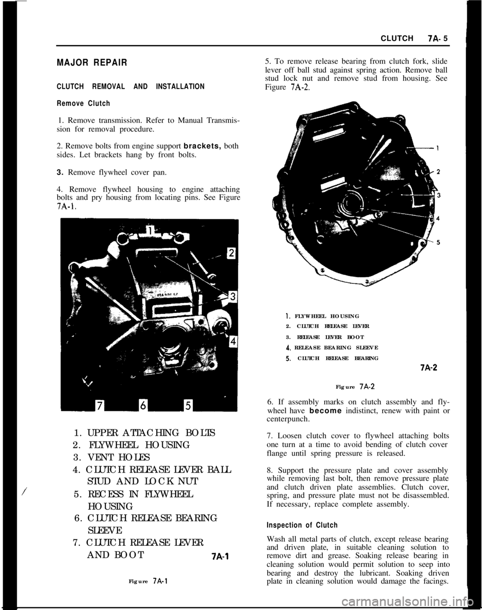
bolts and pry housing from locating pins. See Figure7A-1.
/1. UPPER ATTACHING BOLTS
2. FLYWHEEL HOUSING
3. VENT HOLES
4. CLUTCH RELEASE LEVER BALL
STUD AND LOCK NUT
5. RECESS IN FLYWHEEL
HOUSING
6. CLUTCH RELEASE BEARING
SLEEVE
7. CLUTCH RELEASE LEVER
AND BOOT
7A-1Figure 7A-15. To remove release bearing from clutch fork, slide
lever off ball stud against spring action. Remove ball
stud lock nut and remove stud from housing. See
Figure
7A-2.
1. FLYWHEEL HOUSING
2. CLUTCH RELEASE LEVER
3. RELEASE LEVER BOOT
4. RELEASE BEARING SLEEVES. CLUTCH RELEASE BEARINGi-A-2
Figure 7A-2
6. If assembly marks on clutch assembly and fly-
wheel have become indistinct, renew with paint or
centerpunch.
7. Loosen clutch cover to flywheel attaching bolts
one turn at a time to avoid bending of clutch cover
flange until spring pressure is released.
8. Support the pressure plate and cover assembly
while removing last bolt, then remove pressure plate
and clutch driven plate assemblies. Clutch cover,
spring, and pressure plate must not be disassembled.
If necessary, replace complete assembly.
Inspection of ClutchWash all metal parts of clutch, except release bearing
and driven plate, in suitable cleaning solution to
remove dirt and grease. Soaking release bearing in
cleaning solution would permit solution to seep into
bearing and destroy the lubricant. Soaking driven
plate in cleaning solution would damage the facings.
Page 367 of 625
7A- 61973 OPEL SERVICE MANUAL1. FIywheeI and Pressure PlateExamine friction surfaces of flywheel and pressure
plate for scoring or roughness. Slight roughness may
be smoothed with fine emery cloth, but if surface is
deeply scored or grooved the part should be re-
placed.
2.
CJutch Driven Plate
Inspect driven plate for condition of facings, loose
rivets, broken or very loose torsional springs.
If facings are worn down near rivets or are oily, the
plate assembly should be replaced. A very slight
amount of oil on clutch facings will cause clutch grab
and chatter. A large amount of oil on facings will
cause slippage. Removal of oil by solvents or by buff-
ing is not practical since oil will continue to bleed
from facing material when hot.
When oil is found on driven plate facings, examine
transmission drainback hole, pilot bushing, engine
rear main bearing and other points of possible oil
leakage.
Test the fit of driven plate hub on transmission main
drive gear for an easy sliding fit.
Regardless of whether the old plate or a new one is
to be installed, the plate should be checked for run-
out. Lateral run-out measured at disc circumference
should not exceed
.016 inch.
Inspect clutch release bearing for scoring or exces-
sive wear on front contact face. Test for roughness of
balls and races by pressing and turning front race
slowly. Inspect main drive gear pilot bushing in
crankshaft. If bushing is rough or worn it should be
Figure JA-3replaced. If replacement is necessary, remove bear-
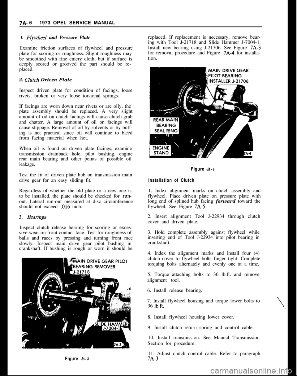
ing with Tool J-21718 and Slide Hammer J-7004-1.
Install new bearing using J-21706. See Figure 7A-3
for removal procedure and Figure 7A-4 for installa-
tion.
\,,
Figure JA-4
Installation of Clutch1. Index alignment marks on clutch assembly and
flywheel. Place driven plate on pressure plate with
long end of splined hub facing forward toward the
flywheel. See Figure 7A-5.
2. Insert alignment Tool J-22934 through clutch
cover and driven plate.
3. Hold complete assembly against flywheel while
inserting end of Tool J-22934 into pilot bearing in
crankshaft.
4. Index the alignment marks and install four (4)
clutch cover to flywheel bolts finger tight. Complete
torquing bolts alternately and evenly one at a time.
5. Torque attaching bolts to 36 lb.ft. and remove
alignment tool.
6. Install release bearing.
7. Install flywheel housing and torque lower bolts to
36
lb.ft.8. Install flywheel housing lower cover.
9. Install clutch return spring and control cable.
10. Install transmission. See Manual Transmission
Section for procedure.
11. Adjust clutch control cable. Refer to paragraph7A-3.
Page 368 of 625
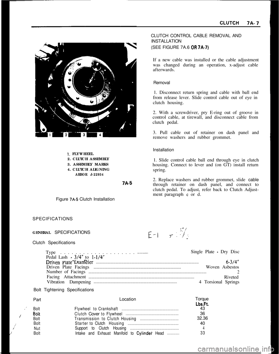
Installation1. FLYWHEEL
2. CLUTCH ASSEMBLY
3. ASSEMBLY MARKS
4. CLUTCH ALIGNING
ARBOR J-229347A-51. Slide control cable ball end through eye in clutch
housing. Connect to lever and (on GT) install return
spring.
2. Replace washers and rubber grommet, slide cable
through retainer on dash panel, and connect to
clutch pedal. To adjust, refer back to Clutch Adjust-
ment paragraph
c or d.
Figure
7A-5 Clutch Installation
SPECIFICATIONS
GENERAL SPECIFICATIONSE-l
I-‘-J- : ,“/’‘~Clutch Specifications
Type. . . . . . . . . . . . . . . . . . . .
Pedal Lash
_ 3/4” to l-1/4”-. -..-.
.........Single Plate - Dry Disc
unvenFlareuamerer.....................................................................................................6-3/4”
Driven Plate Facings
......................................................................................Woven Asbestos
Number of Facings
....................................................................................................................
2Facing Attachment
........................................................................................................Riveted
Vibration Dampening
..................................................................................4 Torsional Springs
Bolt Tightening SpecificationsCLUTCH CONTROL CABLE REMOVAL AND
INSTALLATION
(SEE FIGURE 7A.6
OR 7A-7)
If a new cable was installed or the cable adjustment
was changed during an operation, x-adjust cable
afterwards.
Removal
1. Disconnect return spring and cable with ball end
from release lever. Slide control cable out of eye in
clutch housing.
2. With a screwdriver, pry E-ring out of groove in
control cable, at tirewall, and disconnect cable from
clutch pedal.
3. Pull cable out of retainer on dash panel and
remove washers and rubber grommet.
PartLocationTorque
Lbs.Ft..’
BoltFlywheeltoCrankshaft........................................................43
/BoltClutchCovertoFlywheel....................................................36
BoltTransmissiontoClutchHousing......................................32.36;:
BoltStartertoClutchHousing..................................................40
NutSupport to Clutch Housing................................................4IBoltIntake and Exhaust Manifold to Cylindei Head............33
Page 383 of 625
78.221973 OPEL SERVICE MANUAL
3. Install new bellows. Adhere to distance A
- 8.07”.
See Figure 7B-I 1.
4. Heat up new gearshift lever knob in boiling water
to 176 degrees F. and push it onto gearshift lever
tube. Adhere to distance A .3”, see Figure
7B-15.The gearshift lever tube end is provided with trans-
verse grooves for which reason the old button cannot
be reused. Install gearshift lever.
REPLACING RUBBER DAMPENING PARTS IN
GEARSHIFT LEVER1. Remove gearshift lever.
2. Knock off gearshift lever button and loosen
threaded pin for Bowden control wire attachment.
3. Remove lower snap ring from gearshift lever tube
and pull tube off shift finger.
4. Take off and replace rubber dampening parts.
5. After installation of tube, tighten Bowden control
wire with threaded pin. Prior to tightening, pull ring
must rest on gearshift lever tube and clamping block
on pull ring. See Figure
7B-15.6. Heat up new gearshift lever knob in boiling water
to 176 degrees F. and push it onto gearshift lever
tube. Adhere to distance A
- .3”, see Figure 7B-15.The gearshift lever tube end is provided with trans-
verse grooves for which reason the old button cannot
be reused.
7. Install gearshift lever.
MAJOR REPAIR
TRANSMISSION REMOVAL1. Remove air cleaner. Remove throttle rod from
carburetor and rear support and disconnect battery.
2. Remove screws from fan shroud.
3. Remove gearshift lever (refer to paragraph on ser-
vicing gearshift lever).
4. Support car with frame or wheel stands in the
front or frame stands in the rear.
5. Loosen front exhaust pipe to manifold flange.
6. Remove clutch cable from fork by pushing fork to
disengage the clutch and unsnap cable from slot.
7. Disconnect both wires from backup lamp switch.8. Disconnect speedometer cable from transmission
case extension housing.
9. Unhook parking brake cable return spring and
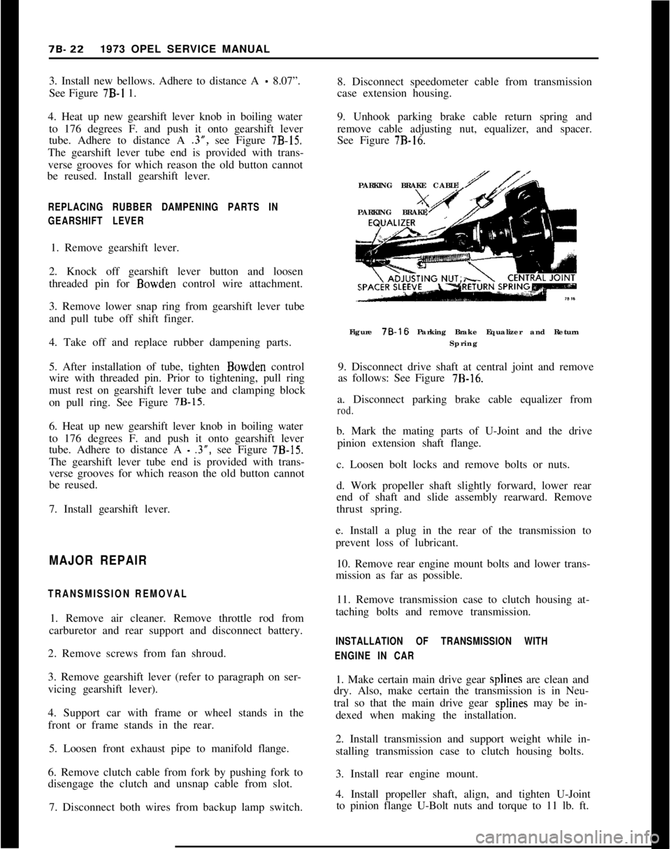
remove cable adjusting nut, equalizer, and spacer.
See Figure
7B-16.PARKING BRAKE CABLE
PARKING BRAKE
Figure 78-16 Parking Brake Equalizer and Return
Spring
9. Disconnect drive shaft at central joint and remove
as follows: See Figure
7B-16.a. Disconnect parking brake cable equalizer from
rod.b. Mark the mating parts of U-Joint and the drive
pinion extension shaft flange.
c. Loosen bolt locks and remove bolts or nuts.
d. Work propeller shaft slightly forward, lower rear
end of shaft and slide assembly rearward. Remove
thrust spring.
e. Install a plug in the rear of the transmission to
prevent loss of lubricant.
10. Remove rear engine mount bolts and lower trans-
mission as far as possible.
11. Remove transmission case to clutch housing at-
taching bolts and remove transmission.
INSTALLATION OF TRANSMISSION WITH
ENGINE IN CAR1. Make certain main drive gear splines are clean and
dry. Also, make certain the transmission is in Neu-
tral so that the main drive gear splines may be in-
dexed when making the installation.
2. Install transmission and support weight while in-
stalling transmission case to clutch housing bolts.
3. Install rear engine mount.
4. Install propeller shaft, align, and tighten U-Joint
to pinion flange U-Bolt nuts and torque to 11 lb. ft.
Page 394 of 625
MANUAL TRANSMISSION70-33
Installing Gearshift Interlock Ball and Gearshift
Thrust Spring1. Install gearshift interlock ball into top transmis-
sion bore and then install gearshift thrust spring.
Installing Transmission Case Cover1. Install case cover gasket, cover, and tighten
screws.
Installing Gearshift Linkages1. Install selector ring and lock nut onto selector
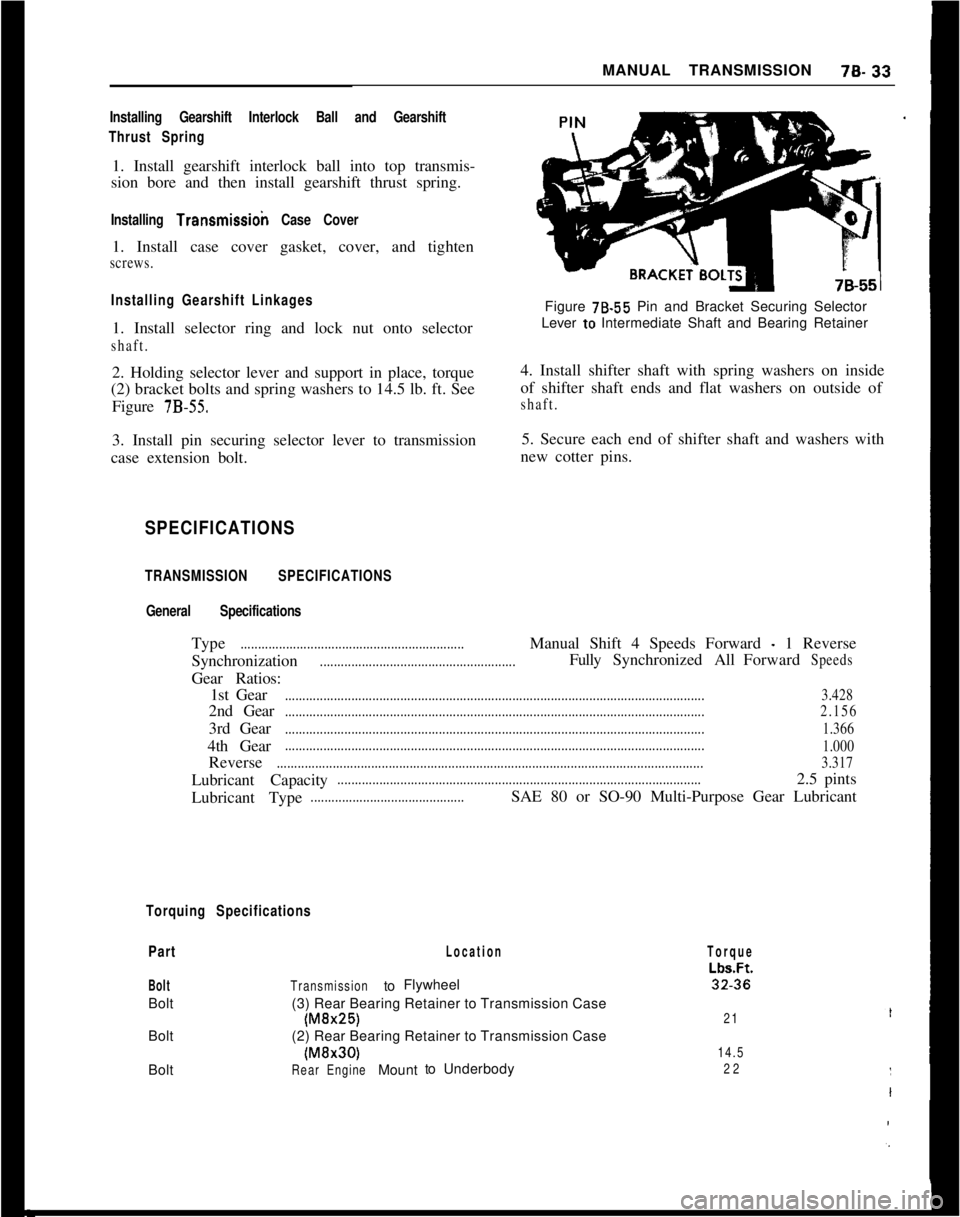
shaft.2. Holding selector lever and support in place, torque
(2) bracket bolts and spring washers to 14.5 lb. ft. See
Figure
7B-55.3. Install pin securing selector lever to transmission
case extension bolt.Figure 78.55 Pin and Bracket Securing Selector
Lever to Intermediate Shaft and Bearing Retainer
4. Install shifter shaft with spring washers on inside
of shifter shaft ends and flat washers on outside ofshaft.5. Secure each end of shifter shaft and washers with
new cotter pins.
SPECIFICATIONS
TRANSMISSION SPECIFICATIONS
General SpecificationsType
................................................................Manual Shift 4 Speeds Forward - 1 Reverse
Synchronization
........................................................FullySynchronizedAllForwardSpeedsGear Ratios:
1st Gear
........................................................................................................................3.4282nd Gear
........................................................................................................................2.1563rd Gear
........................................................................................................................1.3664th Gear
........................................................................................................................
1.000Reverse
..........................................................................................................................3.317Lubricant Capacity
........................................................................................................2.5 pints
Lubricant Type
............................................SAE 80 or SO-90 Multi-Purpose Gear Lubricant
Torquing Specifications
Part
BoltBolt
Bolt
Bolt
Location
TransmissiontoFlywheel
(3) Rear Bearing Retainer to Transmission Case
(M&25)(2) Rear Bearing Retainer to Transmission Case(MBr30)
RearEngineMounttoUnderbody
Torque
Lbs.Ft.32.36
21
14.5
22
Page 455 of 625

7C. 941973 OPEL SERVICE MANUAL
7. Drive out retaining pin and shaft and remove se-
lector detent. See Figure 7C-93.Figure
7C-93Figure
7C-94 - Exploded View of Selector Lever
8. To replace bowden cable in selector lever, knock
off selector handle, remove screws from clamping
piece and pull knob.
9. Remove pull knob and bowden cable, taking care
not to lose lock bolt bushing, thrust springs, ‘and
washer.
10. Place thrust spring, bushing, washer, and thrust
spring onto new bowden cable, in that order, and
insert cable into selector lever.
1 I. Slide pull onto selector lever and clamping piece
onto cable.
12. Heat up new selector lever handle in water to 176
degrees F. and push onto selector lever.
13. Set dimension between pull knob and selector
lever handle at
.4 inch and tighten set screws.
14. Lubricate selector lever detent and shaft. Install
detent, align selector lever with support, install shaft,
and drive in new retaining pin.
15. Install assembly to support housing and install
intermediate selector lever.
16. Install assembly to vehicle and install neutral
start switch.
17. Install console lights and cigar lighter connec-
tions to console and install console to vehicle.
18. Lubricate and connect selector rod to intermedi-
ate selector lever and adjust according to Figure 7C-
198.
MAJOR REPAIRREMOVAL AND INSTALLATION OF AUTOMATIC
TRANSMISSION
Removal
- Opel 1900 and Manta
I. Disconnect battery.
2. Remove dipstick.
3. Remove screws from fan shroud.
4. Remove 2 upper starter bolts.
5. Raise car and provide support for front and rear
and drain oil.
6. Remove bolts from engine support brackets, both
sides. Let brackets hang by front bolts. See Figure7c-105.
7. Remove flywheel cover pan.
8. Remove exhaust pipe from manifold and unhook
rubber tailpipe suspension.
9. Remove drive shaft. Do not misplace thrust spring
in spline.
10. Disconnect cooler lines at flexible hoses.
II. Detach both stabilizer supports from
crossmem-ber to body supports and loosen stabilizer bolts in
lower control arms. See Figure X-84, Callout “B”,
Page 456 of 625
AUTOMATIC TRANSMISSION 7C- 95
12. Place suitable jack under transmission and
remove transmission support bolts.
13. Lower transmission enough to remove detent
cable and modulator vacuum line.
14. Remove speedometer cable.
15. Remove selector lever.
16. Mark flywheel and converter for reassembly in
same position, and remove converter to flywheel
bolts. See Figure 7C-106.17. Remove converter housing to engine bolts and
tiller tube.
18. Pry transmission loose from engine.
19. Keep rear of transmission lower than front to
prevent converter from falling and install converter
holding fixture J-21366. Lower transmission and
move to bench.
Installation. Opel 1900 and Manta1. Assemble transmission to suitable jack and raise
transmission into position. Rotate converter to per-
mit coupling of fly wheel and converter with original
relationship. Remove J-21366.
2. Install tiller tube and converter housing to engine
block bolts. Torque to 35 lb. ft. DO NOT over
torque.
3. Install flywheel to converter bolts. Torque to 30 lb.
ft.4. Install detent cable to transmission.
5. Connect oil cooler lines.
6. Install lower bolt on starter. Torque to 40 lb. ft.
7. Connect shift linkage to transmission.
8. Connect modulator line.
9. Connect speedometer cable.
10. Install transmission support.
11. Install drive shaft. Torque U-Bolts to 18 lb. ft.
12. Install flywheel cover pan. Torque to 15 lb. ft.
13. Install engine support brackets.
14. Reconnect exhaust system.15. Attach stabilizer supports and tighten stabilizer
bolts in lower control arms.
16. Lower car.
17. Install starter bolts. Torque to 40 lb. ft.
18. Reconnect battery.
19. Fill transmission with fluid as described in
Specifications. Check selector lever and detent cable
adjustment.
Removal GT1. Disconnect battery.
2. Remove dipstick.
3. Pull throttle control rod off ball pin.
4. Remove screws from fan shroud.
5. Raise car and provide support for front and rear.
6. Remove heat protection shield from right side to
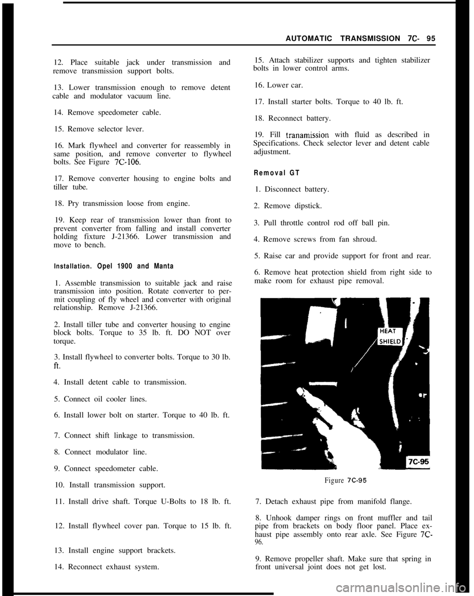
make room for exhaust pipe removal.
Figure 7C-957. Detach exhaust pipe from manifold flange.
8. Unhook damper rings on front muffler and tail
pipe from brackets on body floor panel. Place ex-
haust pipe assembly onto rear axle. See Figure 7C-
96.9. Remove propeller shaft. Make sure that spring in
front universal joint does not get lost.
Page 459 of 625
7C- 981973 OPEL SERVICE MANUAL
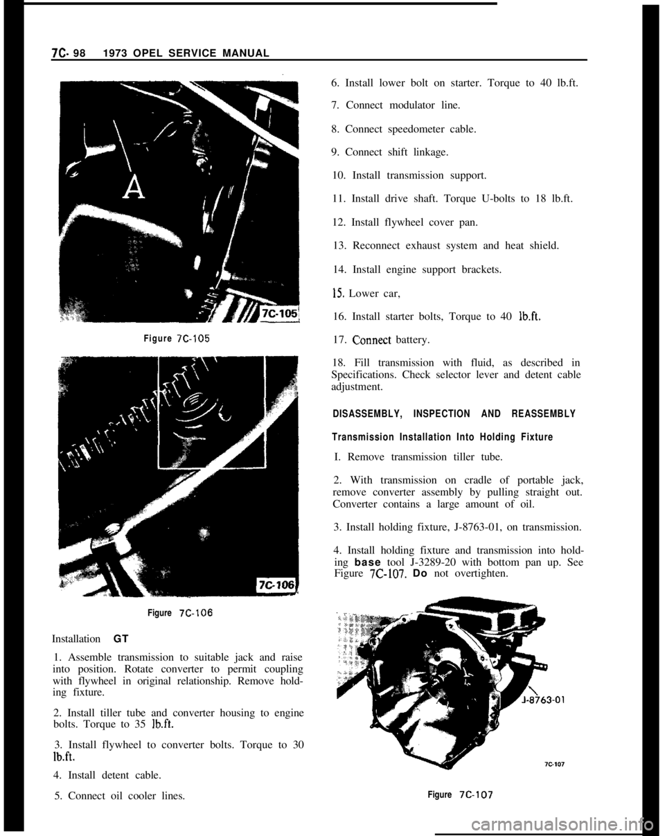
Figure 7C-105Figure
7C-106Installation GT
1. Assemble transmission to suitable jack and raise
into position. Rotate converter to permit coupling
with flywheel in original relationship. Remove hold-
ing fixture.
2. Install tiller tube and converter housing to engine
bolts. Torque to 35
lb.ft.3. Install flywheel to converter bolts. Torque to 30
lb.ft.4. Install detent cable.
5. Connect oil cooler lines.6. Install lower bolt on starter. Torque to 40 lb.ft.
7. Connect modulator line.
8. Connect speedometer cable.
9. Connect shift linkage.
10. Install transmission support.
11. Install drive shaft. Torque U-bolts to 18 lb.ft.
12. Install flywheel cover pan.
13. Reconnect exhaust system and heat shield.
14. Install engine support brackets.
15. Lower car,
16. Install starter bolts, Torque to 40
lb.ft.17.
C:onnect battery.
18. Fill transmission with fluid, as described in
Specifications. Check selector lever and detent cable
adjustment.
DISASSEMBLY, INSPECTION AND REASSEMBLY
Transmission Installation Into Holding FixtureI. Remove transmission tiller tube.
2. With transmission on cradle of portable jack,
remove converter assembly by pulling straight out.
Converter contains a large amount of oil.
3. Install holding fixture, J-8763-01, on transmission.
4. Install holding fixture and transmission into hold-
ing base tool J-3289-20 with bottom pan up. See
Figure
7C-107. Do not overtighten.
Figure
7C-107
Page 496 of 625
AUTOMATIC TRANSMISSION 7C-135
becomes necessary to check the fluid level, the trans-
mission may be checked at room temperature (70
degrees F.) as follows:
1. With manual control lever in Park position start
engine. DO NOT RACE ENGINE. Move manual
control lever through each range.
2. lmmediately check fluid level with selector lever
in Park, engine running, and vehicle on LEVEL sur-
face.At this point, when a reading is made, fluid level on
the dipstick should be I/4” below the “ADD” mark.
3. If additional fluid is required add fluid to bring
level to
l/4” below the “ADD” mark on the dip-
stick.If transmission fluid level is correctly established at
70 degrees F. it will appear at the “FULL” mark on
the dipstick when the transmission reaches normal
operating temperature (180 degrees F.) The fluid
level is set
l/4” below the “ADD” mark on the
dipstick to allow for expansion of the fluid which
occurs as transmission temperatures rise to normal
operating temperature of 180 degrees F.
Do not overfill, as foaming and loss of fluid through
the vent pipe might occur as fluid heats up. If fluid
is too low especially when cold, complete loss
of’drive may result which can cause transmission fail-
ure.
2.Draining oilpan and rep/a&g strainer assembly.
(a) Raise car on hoist or p/ace OnJxk stands, and
provide container to collect draining fluid.
(b) Remove oil pan and gasket. Discard gasket.
(c) Drain fluid from oil pan. Clean pan with solvent
and dry thoroughly with clean compressed air.
(d) Remove strainer assembly, strainer gasket and
discard.
(e) Install new oil strainer gasket. Install new strainer
assembly.
(f) Install new gasket on oil pan and install pan.
Tighten attaching bolts to 7-10 lb. ft.
(g) Lower car and add approximately three (3) pints
of transmission fluid through filler tube.
(h) With manual control lever in Park position, start
engine. DO NOT RACE ENGINE. Move manual
control lever through each range.
(i) Immediately check fluid level with selector leverin Park, engine running, and vehicle on LEVEL
sur-
face.(i) Add additional fluid to bring level to
l/4” below
the “ADD” mark on the dipstick. Do not overfill.
3.Adding Fluid to Fill Dry Transmission and Con-
verter Assembly
The fluid capacity of the Opel Three Speed Auto-
matic transmission and converter assembly is ap-
proximately IO-l/2 pints, but correct level is
determined by the mark on the dipstick rather than
by amount added. In cases of transmission overhaul,
when a complete fill is required, including a new
converter proceed as follows:
(a) Add approximately 10-l/2 pints of transmission
fluid through tiller tube.
The converter should be replaced on any major fail-
ure, such as a clutch or gearset, and an excessive
amount of foreign material is indicated in the pan. If
installation of a new converter is not required add
approximately five (5) pints of transmission fluid.
(b) With manual control lever in Park position start
engine and run at 1000 RPM. DO NOT RACE EN-
GINE. Move manual control lever through each
range.
(c) Immediately check fluid level with selector lever
in Park, engine running, and vehicle on LEVEL
sur-
face.(d) Add additional fluid to bring level to
l/4” below
the “ADD” mark on the dipstick. Do not overfill.
Opel Three Speed Automatic Transmission Towing
Instructions
If an Opel equipped with an automatic transmission
must be towed, the following precautions must be
observed:
The car may be towed safely on its rear wheels with
the shift lever in neutral position at speeds of 35 miles
per hour or less under most conditions.
However, the drive shaft must be disconnected or the
car towed on its front wheels if:
a. Tow speeds in excess of 35 mph are necessary.
b. Car must be towed for extended distances (over 50
miles).
c. Transmission is not operating properly.
If car is towed on its front wheels, the steering wheel