wheel torque OPEL GT-R 1973 Owner's Guide
[x] Cancel search | Manufacturer: OPEL, Model Year: 1973, Model line: GT-R, Model: OPEL GT-R 1973Pages: 625, PDF Size: 17.22 MB
Page 225 of 625
3G- 581873 OPEL SERVICE MANUALTire Wear IrregularitiesAn additional cause of vibrations may sometimes be
tire wear irregularities. These can also produce noise
disturbances, and can be generally corrected by
rotating the tires, Figure
3G-6. Before proceeding
further, locate and correct the cause of the irregular
tire wear. See Figure
3G-7.Use the criss-cross method of rotation of tires only
when all four tires are equally worn. In some in-
stances, it may be necessary to put the truest running
assemblies (those with the lowest tolerances) on the
front of the car.
Wheel Nut Torque end Tightening SpecificationsDuring all wheel installations, it is important to use
the correct procedures for installing wheel nuts and
torquing them uniformly and in proper sequence.
This is important in order to avoid possible distor-
tion of the brake drum or disc, and to minimize
damage to lug and nut threads and wheel stud holes.
To assure uniform tightening of wheel lug nuts, the
following procedure is recommended:
1. Install wheel lug nuts in a criss-cross pattern and
tighten just enough to seat wheel against hub. This
assures proper piloting of the wheel on its hub.
2. Tighten lug nuts uniformly to proper torque of 65
Ib.ft. using criss-cross pattern.
An impact wrench should not be used, as uniform
torque control cannot be maintained.
Summary of Diagnosis end Correction of Tire and
Wheel Vibration1. Inflate all tires to recommended pressure and
road-test car with owner to define problem.
2. Spin front tire/wheel assemblies with wheel driv-
ing equipment. Rear wheels may be spun with tires
off the ground and with one wheel held at a time. The
offending tire may cause vibration that may be felt
by touching the bumper or fender. By process of
elimination, determine offending tire/wheel assem-
bly.
3. Check for tire/wheel unbalance. Balance, if neces-
sary.4. Check each tire/wheel assembly on the car for
radial runout on the tire tread. Wheel and tire assem-
blies exceeding
.050 inches may be considered as
offending assemblies. Offending tire/wheel assemblyshould be deflated and the tire repositioned (indexed)
180 degrees from original location.
5. After repositioning, rebalance tire/wheel assembly
(static and dynamic preferred).
6. Test drive and evaluate correction.
The following procedure should be used to determine
cause of roughness or vibration with car in operation
at various speeds:
I. Jack up all wheels having jack support rear end of
car at center of rear axle housing.
2. With transmission in “Drive”, run engine at vari-
ous car speeds to note speeds at which vibration or
roughness occurs.
3. Remove rear wheels and run engine again at the
critical speeds noted in step 2. If roughness is gone,
the condition is caused by unbalanced wheel and tire
assemblies.
4. If roughness still exists with rear wheels removed,
remove rear brake drums and repeat the running
test. Elimination of the roughness indicates out of
balance brake drums.
5. If roughness still exists with brake drums
removed, run engine with transmission in “Neutral”.
Elimination of the roughness indicates that propeller
shaft is out of balance. Continued roughness indi-
cates an out-of- balance engine.
ABNORMAL TIRE WEAR
General Operating ConditionsAssuming that there is no misalignment condition to
cause abnormal wear, the life of tires depends largely
upon car operation conditions and driving habits.
Tires wear at a much faster rate in some localities
than in others because of road and operating condi-
tions. Some types of roads are much more abrasive
than others. Tire wear is also dependent upon the
number of hills and mountains which the car must
go up and down, the severity of grades, the number
of starts and stops, driging speeds, the amount of rain
and snow, and prevailing temperatures. Tire
wear
increases rapidly with speed, temperature, and loadon tire. Tires used at low speeds, in cool climates, or
with light loads will have longer life than tires used
for high-speed driving in hot climates with heavy
loads.
Driving habits have a very important hearing on tire
life. A careful driver may obtain much greater mile-
age from a set of tires than would be obtained by a
Page 230 of 625

WHEELS AND TIRES36-63would require inflation pressures above the maximum allowable, speed must be
limited to 75 miles per hour.
3.Cool tire inflation pressure: After vehicle has been inoperative for 3 hours
or more, or driven less than one mile. Hot tire inflation pressure: After vehicle
has been driven
10 miles or more at 60-70 MPH.
4.Vehicles with luggage racks do not have a vehicle load limit greater than
specified.
5. When towing trailers, the allowable passenger and cargo load must be
reduced by an amount equal to the trailer tongue load on the trailer hitch.
Torque SpecificationWheelNuts
. . . . . . . . . . . . . . . . . . . . . . . . . . . . . . . . . . . . . . . . . . . . . . . . . . . . . . . . . . . . . . . . . . . . . . . . . . . . . . . . . .65lb.ft.
IFigure 3G-8 Wheel and Tire - Exploded View
Page 241 of 625
4B- 101973 OPEL SERVICE MANUAL
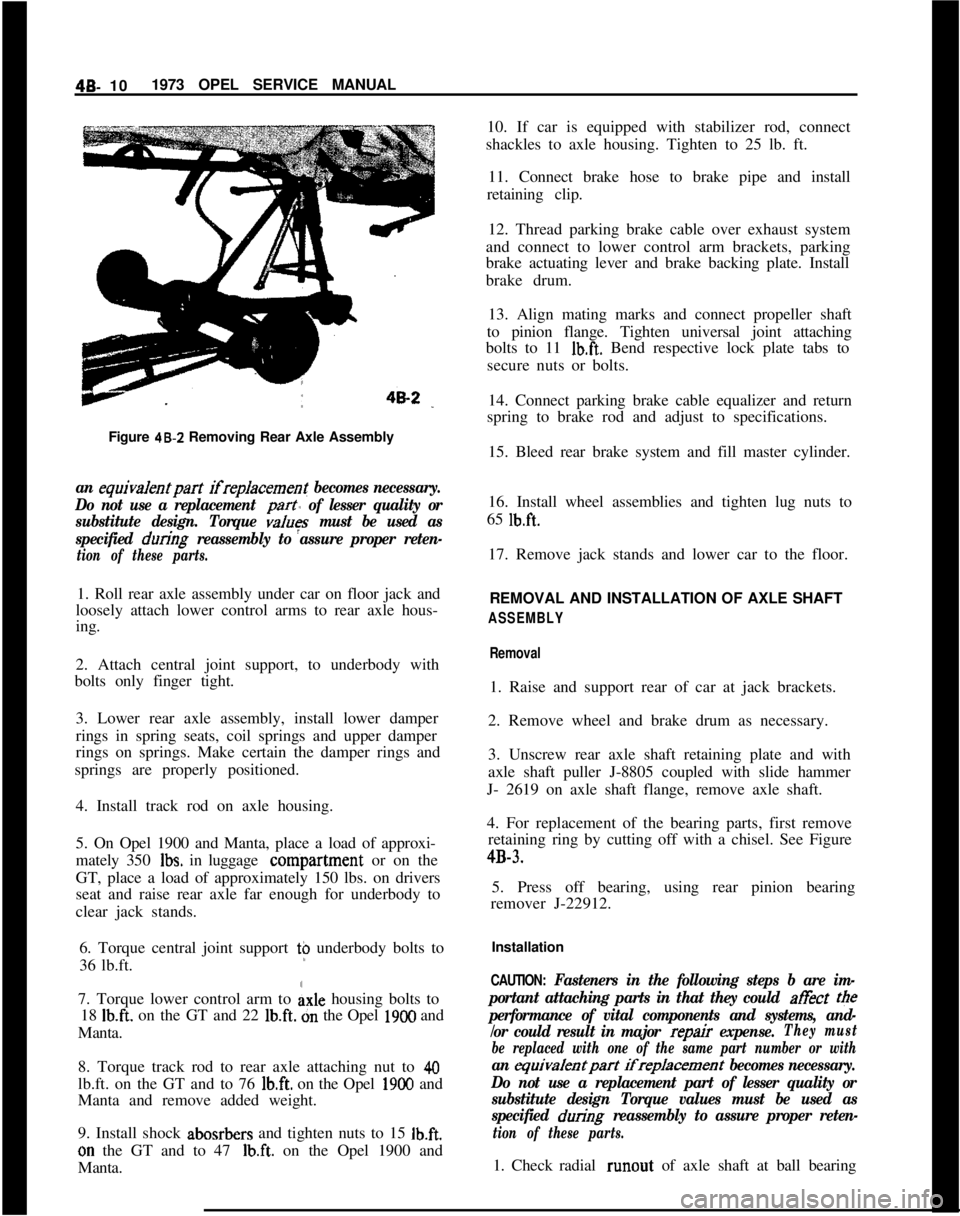
Figure 48-Z Removing Rear Axle Assemblyan equiva/entpart ifreplacement becomes necessary.
Do not use a replacement
part of lesser quality or
substitute design. Torque
values must be used as
specified
during reassembly to assure proper reten-
tion of these parts.1. Roll rear axle assembly under car on floor jack and
loosely attach lower control arms to rear axle hous-
ing.
2. Attach central joint support, to underbody with
bolts only finger tight.
3. Lower rear axle assembly, install lower damper
rings in spring seats, coil springs and upper damper
rings on springs. Make certain the damper rings and
springs are properly positioned.
4. Install track rod on axle housing.
5. On Opel 1900 and Manta, place a load of approxi-
mately 350
Ibs. in luggage conipartment or on the
GT, place a load of approximately 150 lbs. on drivers
seat and raise rear axle far enough for underbody to
clear jack stands.
6. Torque central joint support t$ underbody bolts to
36 lb.ft.
7. Torque lower control arm to
Axle housing bolts to
18
Ib.ft. on the GT and 22 lb.ft. dn the Opel 1900 and
Manta.
8. Torque track rod to rear axle attaching nut to
40lb.ft. on the GT and to 76
lb.ft. on the Opel 1900 and
Manta and remove added weight.
9. Install shock abosrbers and tighten nuts to 15
Ib.ft.on the GT and to 47
Ib.ft. on the Opel 1900 and
Manta.10. If car is equipped with stabilizer rod, connect
shackles to axle housing. Tighten to 25 lb. ft.
11. Connect brake hose to brake pipe and install
retaining clip.
12. Thread parking brake cable over exhaust system
and connect to lower control arm brackets, parking
brake actuating lever and brake backing plate. Install
brake drum.
13. Align mating marks and connect propeller shaft
to pinion flange. Tighten universal joint attaching
bolts to 11
Ib.ft. Bend respective lock plate tabs to
secure nuts or bolts.
14. Connect parking brake cable equalizer and return
spring to brake rod and adjust to specifications.
15. Bleed rear brake system and fill master cylinder.
16. Install wheel assemblies and tighten lug nuts to
65
lb.ft.17. Remove jack stands and lower car to the floor.
REMOVAL AND INSTALLATION OF AXLE SHAFT
ASSEMBLY
Removal1. Raise and support rear of car at jack brackets.
2. Remove wheel and brake drum as necessary.
3. Unscrew rear axle shaft retaining plate and with
axle shaft puller J-8805 coupled with slide hammer
J- 2619 on axle shaft flange, remove axle shaft.
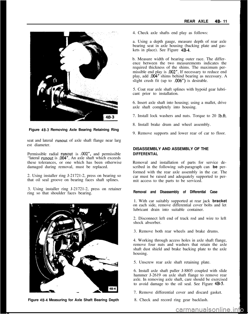
4. For replacement of the bearing parts, first remove
retaining ring by cutting off with a chisel. See Figure4B-3.
5. Press off bearing, using rear pinion bearing
remover J-22912.
Installation
CAUTION: Fasteners in the following steps b are im-
portant attaching parts in that they could at&t
tee
performance of vital components and systems, and-
/or could result in major
repair expense.They must
be replaced with one of the same part number or with
an equivalentpart ifreplacement becomes necessary.
Do not use a replacement part of lesser quality or
substitute design Torque values must be used as
specified
during reassembly to assure proper reten-
tion of these parts.1. Check radial runout of axle shaft at ball bearing
Page 242 of 625
REAR AXLE40- 11
Figure
48-3 Removing Axle Bearing Retaining Ring
seat and lateral runout of axle shaft flange near larg
est diameter.
Permissible radial runout is .002”, and permissible
“lateral runout is
.OO4”. An axle shaft which exceeds
these tolerances, or one which has been otherwise
damaged during removal, must be replaced.
2. Using installer ring J-21721-2, press on bearing so
that oil seal groove on bearing faces shaft splines.
3. Using installer ring J-21721-2, press on retainer
ring so that shoulder faces bearing.
Figure 48.4 Measuring for Axle Shaft Bearing Depth4. Check axle shafts end play as follows:
a. Using a depth gauge, measure depth of rear axle
bearing seat in axle housing (backing plate and gas-
kets in place). See Figure
4B-4.b. Measure width of bearing outer race. The differ-
ence between the two measurements indicates the
required thickness of the shims. The maximum per-
missible end play is .002”. If necessary to reduce end
play, add
,004” shims behind bearing as necessary. A
slight crush fit (up to ,006”) is desirable.
5. Coat rear axle shaft splines with hypoid gear lubri-
cant prior to installation.
6. Insert axle shaft into housing; using a mallet, drive
axle shaft completely into housing.
7. Install lock washers and nuts. Torque to 20
Ib.ft.8. Install brake drum and wheel assembly.
9. Remove supports and lower rear of car to floor.
DISASSEMBLY AND ASSEMBLY OF THE
DIFFERENTIALRemoval and installation of parts for service de-
scribed in the following sub-paragraph can be per-
formed with the rear axle assembly in the car. The
car must be raised and adequately supported to per-
mit access to the parts to be serviced.
Removal and Disassembly of Differential Case1. With car suitably supported at rear jack bracket
on each side, remove differential cover bolts and let
lubricant drain into suitable container.
2. Disconnect left end of track rod and wire to left
shock absorber.
3. Remove both rear wheels and brake drums.
4. Working through access holes in axle shaft flange,
remove four nuts and washers that retain the axle
shaft dust shield and brake backing plate to the axle
housing.
5. Unscrew rear axle shaft retaining plate.
6. Install axle shaft puller J-8805 coupled with slide
hammer J-2619 on axle shaft flange to remove rear
axle. In removing axle shaft, care should be exercised
to avoid damage to the oil seal. See Figure
4B-5.7. Remove differential cover and discard gasket.
8. Check and record ring gear backlash.
Page 272 of 625
DISC BRAKES5B- 13
Condition
Possible CauseCorrection
2. Front end out of line.2. Check and align to manufac-
turer’s specifications.
3. Unmatched tires on sameaxle.3. Tires with approximately the
same amount of tread should be used
on the same axle.
4. Restricted brake tubes
or hoses.4. Check for soft hoses and damaged
lines. Replace with new hoses and
new double-walled steel brake
tubing.
5. Malfunctioning caliper
assembly.5. Frozen caliper
- check for
stuck or sluggish pistons, proper
lubrication.
6. Defective or damaged
shoe and lining (grease or
brake fluid on lining or
bent shoe).6. Install new shoe and lining in
complete axle sets.
7. Malfunctioning rear
brakes.7. Check for brake adjustment,
defective lining (grease or brake
fluid on lining) or defective wheel
cylinders. Repair as necessary.
8. Loose suspension parts.
9. Loose calipers.8. Check all suspension mountings.
9. Check and torque bolts to
specifications.
Brake Roughness or Chatter
(Pedal Pulsates)
1. Excessive lateralrunout.1. Check per instructions and
replace or machine the rotor, if not
within specifications.
2. Parallelism not within
specifications.2. Check per instructions and replace
or machine the rotor, if not within
specifications.
3. Wheel bearings not
adjusted.3. Adjust wheel bearings to correct
specifications.
4. Rear drums out of round.4. Check runout and, if not within
specifications, turn the drums within
specifications.
5. Shoe reversed (steel
against iron).5. Replace shoe and lining and
machine rotor within specifications.
ExcesGve Pedal Effort1. Malfunctioning power
brake.1. Check power brake and repair,
if necessary.
Page 276 of 625
DISC BRAKES58.17a tine cut file.Do not use any solvent except dena-
tured alcohol. Do not use a
metaIJic scraper too/.8. With a punch, drive one dowel pin from inboard
side through caliper and friction pads to stop. Install
new cross-shaped retaining spring under installed
dowel pin, then install second dowel pin. Loose tit-
ting dowel pins must be replaced.
9. Before operating vehicle, depress brake pedal sev-
eral times to adjust friction pads to brake discs.
Check brake fluid level and add fluid as necessary to
bring level up to “MAX” on reservoir.
Car owners must be informed that a break-in period
exists for new friction pads, and that they must avoid
unnecessary, forceful braking during the first 125
miles after installation of new friction pads.
Checking Brake Disc for Lateral Runout1. Remove front wheel assembly.
2. Remove front wheel bearing hub cap and spindle
nut cotter pin. Tighten spindle nut until all free play
is removed from wheel bearings.
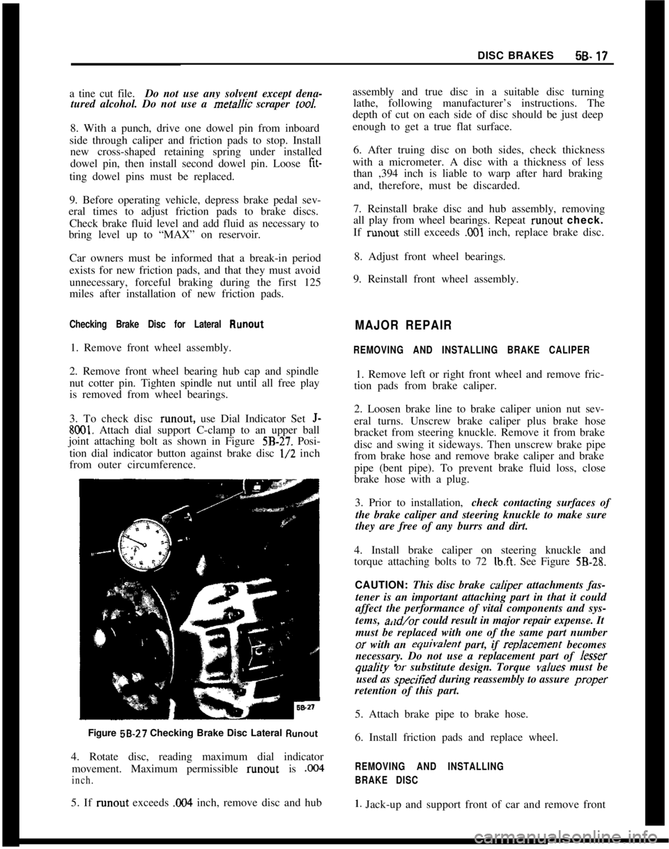
3. To check disc runout, use Dial Indicator Set
J-
8001. Attach dial support C-clamp to an upper ball
joint attaching bolt as shown in Figure
5B-27. Posi-
tion dial indicator button against brake disc
l/2 inch
from outer circumference.
Figure 58-27 Checking Brake Disc Lateral
Runout4. Rotate disc, reading maximum dial indicator
movement. Maximum permissible runout is
,004
inch.5. If runout exceeds
0% inch, remove disc and hubassembly and true disc in a suitable disc turning
lathe, following manufacturer’s instructions. The
depth of cut on each side of disc should be just deep
enough to get a true flat surface.
6. After truing disc on both sides, check thickness
with a micrometer. A disc with a thickness of less
than ,394 inch is liable to warp after hard braking
and, therefore, must be discarded.
7. Reinstall brake disc and hub assembly, removing
all play from wheel bearings. Repeat runout check.
If runout still exceeds
,001 inch, replace brake disc.
8. Adjust front wheel bearings.
9. Reinstall front wheel assembly.
MAJOR REPAIR
REMOVING AND INSTALLING BRAKE CALIPER1. Remove left or right front wheel and remove fric-
tion pads from brake caliper.
2. Loosen brake line to brake caliper union nut sev-
eral turns. Unscrew brake caliper plus brake hose
bracket from steering knuckle. Remove it from brake
disc and swing it sideways. Then unscrew brake pipe
from brake hose and remove brake caliper and brake
pipe (bent pipe). To prevent brake fluid loss, close
brake hose with a plug.
3. Prior to installation,check contacting surfaces of
the brake caliper and steering knuckle to make sure
they are free of any burrs and dirt.
4. Install brake caliper on steering knuckle and
torque attaching bolts to 72
lb.ft. See Figure 5B-28.CAUTION: This disc brake
cah@er attachments fas-
tener is an important attaching part in that it could
affect the performance of vital components and sys-
tems, a,ld/or could result in major repair expense. It
must be replaced with one of the same part numberor with an equivafent part, if repfacement becomes
necessary. Do not use a replacement part of Jesser
quaJity ‘or substitute design. Torque vafues must be
used as specitied during reassembly to assure proper
retention of this part.
5. Attach brake pipe to brake hose.
6. Install friction pads and replace wheel.
REMOVING AND INSTALLING
BRAKE DISC
1. Jack-up and support front of car and remove front
Page 278 of 625
DISC BRAKES5B- 19
CAUTION:
Fasteners in Steps 7 and 9 are important
attachingparts in that they cooId affect theperfom-
ante of vital components and systems, and/or couJd
resuJt in major repair expense. They must be re-
placed with one of the same part number or with an
equivaJent part if repJacement becomes necessary.
Do not use a replacement part
or Jesser quaJity or
substitute design. Torque
vaJues must be used as
specified during
reassembJy to assure proper reten-
tion of these parts.7. Install brake disc on wheel hub and torque attach-
ing bolts to 36
Ib.ft. If old brake disc is reused, pay
attention to locator marks on brake disc and wheel
hub.8. Prior to installing brake disc and hub assembly to
steering knuckle, check lubrication of both roller
bearings and quantity of grease in cavity of wheel
hub. If necessary, repack front wheel bearings.
9. Adjust front wheel bearing clearance and tighten
brake caliper to steering knuckle, attaching bolts to
a torque of 72
lb.ft. Prior to installing brake caliper
to steering knuckle, ensure that all contacting sur-
faces are free of dirt and burrs. Also make sure that
the friction pads are not damaged when sliding the
brake caliper onto brake disc.
10. Install wheel assembly, remove supports and
lower front of car.
REMOVING AND INSTALLING
BRAKE DISC SHIELD
Removal
1. Remove brake disc.
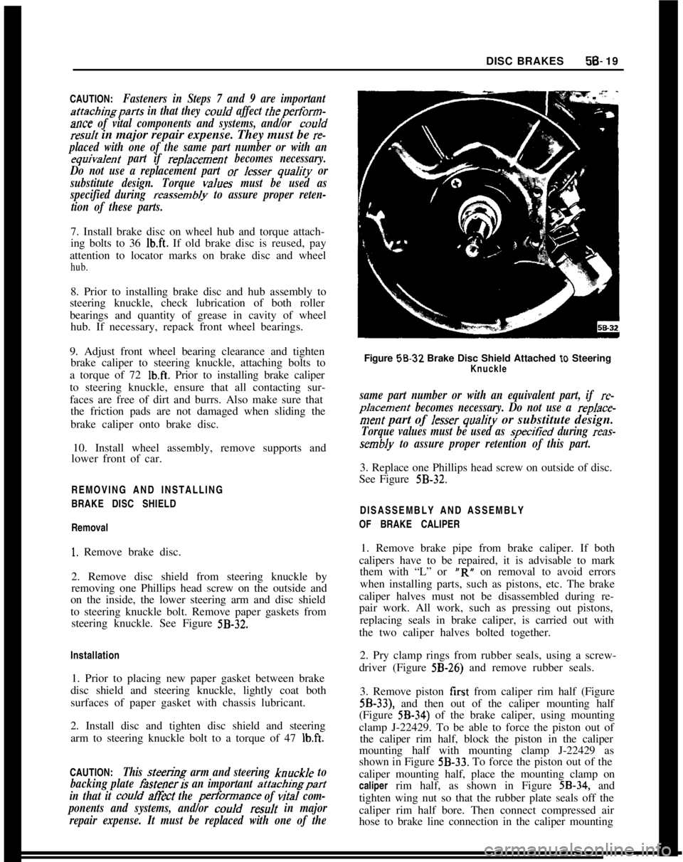
2. Remove disc shield from steering knuckle by
removing one Phillips head screw on the outside and
on the inside, the lower steering arm and disc shield
to steering knuckle bolt. Remove paper gaskets from
steering knuckle. See Figure
5B-32.Installation
1. Prior to placing new paper gasket between brake
disc shield and steering knuckle, lightly coat both
surfaces of paper gasket with chassis lubricant.
2. Install disc and tighten disc shield and steering
arm to steering knuckle bolt to a torque of 47
lb.ft.CAUTION:
This steen;Og arm and steering knuckJe to
backing plate
fisteneris an important attachingpart
in that it
couJd at&t the performance of viral com-
ponents and systems, and/or
couJd resuJt in major
repair expense. It must be replaced with one of theFigure 58-32 Brake Disc Shield Attached
to SteeringKnuckle
same part number or with an equivalent part, if re-
pJacement becomes necessary. Do not use a rep/ace-
merit part of Jesser quaJity or substitute design.
Torque values must be used as specitied during reas-
sembly to assure proper retention of this part.3. Replace one Phillips head screw on outside of disc.
See Figure
5B-32.DISASSEMBLY AND ASSEMBLY
OF BRAKE CALIPER
1. Remove brake pipe from brake caliper. If both
calipers have to be repaired, it is advisable to mark
them with “L” or “R” on removal to avoid errors
when installing parts, such as pistons, etc. The brake
caliper halves must not be disassembled during re-
pair work. All work, such as pressing out pistons,
replacing seals in brake caliper, is carried out with
the two caliper halves bolted together.
2. Pry clamp rings from rubber seals, using a screw-
driver (Figure
5B-26) and remove rubber seals.
3. Remove piston first from caliper rim half (Figure
5B-33), and then out of the caliper mounting half
(Figure
5B-34) of the brake caliper, using mounting
clamp J-22429. To be able to force the piston out of
the caliper rim half, block the piston in the caliper
mounting half with mounting clamp J-22429 as
shown in Figure
5B-33. To force the piston out of the
caliper mounting half, place the mounting clamp on
caliper rim half, as shown in Figure
5B-34, and
tighten wing nut so that the rubber plate seals off the
caliper rim half bore. Then connect compressed air
hose to brake line connection in the caliper mounting
Page 280 of 625
DISC BRAKES5B- 21caliper half collars and the clamp rings are correctly
positioned on rubber seals.
12. Install brake caliper on steering knuckle, torqu-
ing bolts to 72 lb.ft.or with an equivalent part, if replacement becomes
necessary. Do not use a replacement part of lesser
quality or substitute design. Torque values must be
used as specified during reassembly to assure proper
retention of this part.
CAUTION: This disc brake caliper attachments fas-
tener is an important attaching part in that it couldatExt the performance of vital components and sys-
tems, and/or could result in
ma@r repair expense. It
must be replaced with one of the
same part number13. Attach brake pipe to caliper and torque to 22
lb.ft.14. Bleed brakes as necessary.
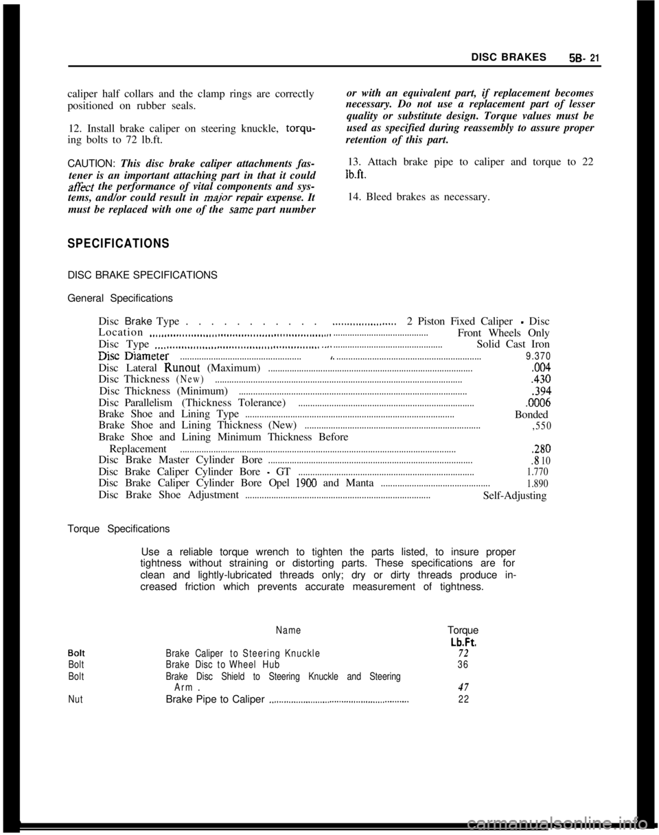
SPECIFICATIONSDISC BRAKE SPECIFICATIONS
General Specifications
DiscBrakeType. . . . . . . . . . .
Location
..,,.,..__....__.,,.,,,................,,,................,....Disc Type
.._.......................................................I.-. -.
......................2 Piston Fixed Caliper - Disc
........................................Front Wheels Only
..............................................Solid Cast Iron
useuameter...................................................,..............................................................9.370Disc Lateral Runout (Maximum)
......................................................................................,004DiscThickness
(New).........................................................................................................430DiscThickness(Minimum)
................................................................................................,394DiscParallelism(ThicknessTolerance)
...........................................................................0006Brake Shoe and Lining Type
........................................................................................Bonded
Brake Shoe and Lining Thickness (New)
..........................................................................
,550Brake Shoe and Lining Minimum Thickness Before
Replacement
....................................................................................................................,280Disc Brake Master Cylinder Bore
.......................................................................................8 10Disc Brake Caliper Cylinder Bore
- GT..........................................................................1.770Disc Brake Caliper Cylinder Bore Opel
1900 and Manta..............................................
1.890Disc Brake Shoe Adjustment
..............................................................................Self-Adjusting
Torque Specifications
Use a reliable torque wrench to tighten the parts listed, to insure proper
tightness without straining or distorting parts. These specifications are for
clean and lightly-lubricated threads only; dry or dirty threads produce in-
creased friction which prevents accurate measurement of tightness.
Bolt
Bolt
Bolt
NutName
BrakeCalipertoSteeringKnuckle
BrakeDisctoWheelHub
Brake Disc Shield to Steering Knuckle and Steering
Arm.
Brake Pipe to Caliper
.,.,...............................,......................Torque
Lb.Ft.
72
36
47
22
Page 290 of 625
DRUM BRAKES5c- 31
remove grooves, and the ridges in the lining should
be lightly removed with a lining grinder.
If brake linings are more than half worn, but do not
need replacement, the drum should be polished with
fine emery cloth but should not be rebored. At this
stage, eliminating the grooves in drum and smooth-
ing the ridges on lining would necessitate removal of
too much metal and lining, while if left alone, the
grooves and ridges match and satisfactory service
can be obtained.
If brake linings are to be replaced, a grooved drum
should be rebored for use with oversize linings. A
grooved drum, if used with new lining, will not only
wear the lining but will make it
diff%xlt, if not im-
possible, to obtain etXcient brake performance.
Out-of-Round DrumAn out-of-round drum makes accurate brake shoe
adjustment impossible and is likely to cause excessive
wear of other parts of brake mechanism due to its
eccentric action. An out-of-round drum can also
cause brake pulsation. Maximum permissible drumrunout is 004”. A drum that has more run-out than
this should be rebored. Runout can be accurately
checked by using an inside micrometer fitted with
proper extension rods.
When measuring a drum for run-out, take measure-
ments at open and closed edges of machined surface
and at right angles to each other.
Turning Brake DrumsIf a brake drum is to be turned, enough metal should
be removed to obtain a true, smooth braking surface.
Measure brake drum diameter; standard drum inner
diameter is 9.060”. Drums may be turned to an over-
size of ,030”. If maximum inner diameter after turn-
ing exceeds 9.090”, brake drum will have to be
replaced. Removal of more metal will affect dissipa-
tion of heat and may cause distortion of the drum.
1. Remove rear wheels and drums.
2. Mount brake drum on brake drum lathe and turn
drums as necessary, within limits.
3. After turning, check drum diameter. Inner diame-
ter not to exceed 9.090.
4. A newly-bored drum should always have center
contact with brake shoes. For this reason, arc grind
linings to
.OlO” under drum radius, or to ,020” under
drum diameter.
5. Clean and install drums and wheels.
BRAKE WHEEL CYLINDER OVERHAUL1. Remove wheel, drum, and brake shoes. Be careful
not to get grease or dirt on brake lining.
2. Disconnect brake pipe or hose from wheel cylinder
and cover opening with tape to prevent entrance of
dirt. Remove wheel cylinder from backing plate.
3. Remove boots, pistons, cups, and spring from cyl-
inder. Remove bleeder valve.
4. Discard rubber boots and piston cups. Thoroughly
clean all other parts with hydraulic brake fluid orDeclene. Do not use anti-freeze, alcohol, gasoline,
kerosene, or any other cleaning fluid that might con-
tain even a trace of mineral oil.
5. Inspect pistons and cylinder bore for scores, scrat-
ches, or corrosion. Light scratches may be polished
with crocus cloth. Do not use emery cloth or sandpa-
per.
Shght corro~on may be cleaned wth tine steel
wool. If scratches or corroded spots are too deep to
be polished satisfactorily, the cylinder should be re-
placed since honing is not recommended.
6. Dip internal parts in brake fluid and reassembly
wheel cylinder. When installing piston cups, use care
to avoid damaging the edges.
7. If the rear wheel backing plate is removed: Always
install new paper gaskets one on each side
- on the
backing plate. Prior to installation, lightly coat paper
gaskets with chassis lubricant. Torque backing plate
to rear axle housing bolts to 43
lb.ft. and wheel brake
cylinder to backing plate bolts to 5
lb.ft. Install wheel
cylinder on brake backing plate and connect brake
pipe or hose.
8. Install brake shoes, drum, and wheel, then flush
and bleed hydraulic system.
9. Adjust brakes, then road test car for brake per-
formance.
CAUTION:This brake backing plate to rear axle fis-
tener is an important attaching part in that it could
affect the performance of vital components and sys-
tems, and/or could result in major repair expense. It
must be replaced with one of the same part number
or with an equivalent part, if replacement becomes
necessary. Do not
use a replacement part of lesser
quahty or substitute design. Torque v&es must be
used as specified during reassembly to assure proper
retention of this part.
REPLACING BRAKE PIPESAny brake pipe assembly which is needed must be
made up from service bulk tubing and fittings. All
brake pipes must be made of tin or copper coated
wrapped steel tubing with the ends double lap flared.
Page 291 of 625
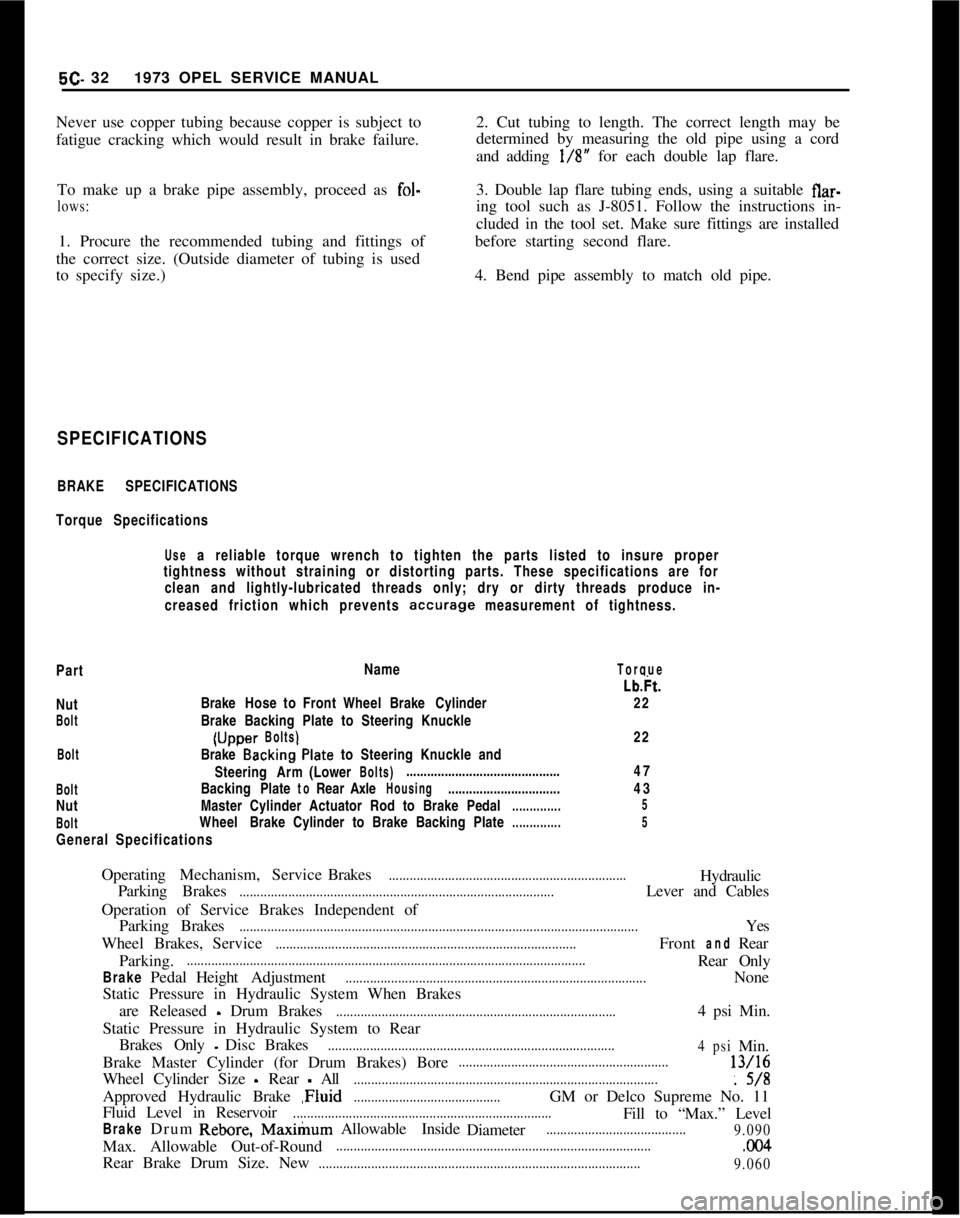
5C- 321973 OPEL SERVICE MANUAL
Never use copper tubing because copper is subject to
fatigue cracking which would result in brake failure.2. Cut tubing to length. The correct length may be
determined by measuring the old pipe using a cord
and adding l/8” for each double lap flare.
To make up a brake pipe assembly, proceed as fol-
lows:3. Double lap flare tubing ends, using a suitable flar-
ing tool such as J-8051. Follow the instructions in-
cluded in the tool set. Make sure fittings are installed
1. Procure the recommended tubing and fittings of
the correct size. (Outside diameter of tubing is used
to specify size.)before starting second flare.
4. Bend pipe assembly to match old pipe.
SPECIFICATIONS
BRAKE SPECIFICATIONS
Torque Specifications
Use a reliable torque wrench to tighten the parts listed to insure proper
tightness without straining or distorting parts. These specifications are for
clean and lightly-lubricated threads only; dry or dirty threads produce in-
creased friction which prevents
accurage measurement of tightness.
PartName
TorqueNut
BoltBrakeHose to Front WheelBrake Cylinder
Brake Backing Plate to Steering Knuckle(Uccer
Bolts)Lb&.
22
22...BoltBrake Backing’Plate to Steering Knuckle and
SteeringArm(Lower
Bolts)............................................
BoltBackingPlatetoRearAxleHousing................................
NutMaster Cylinder Actuator Rod to BrakePedal
..............
BoltWheelBrake Cylinder to Brake Backing Plate
..............
General Specifications47
43
5
5OperatingMechanism,ServiceBrakes
....................................................................Hydraulic
Parking Brakes
..........................................................................................Lever and Cables
Operation of Service Brakes Independent of
ParkingBrakes
..................................................................................................................Yes
WheelBrakes,Service
......................................................................................FrontandRear
Parking.
..................................................................................................................Rear Only
BrakePedalHeightAdjustment......................................................................................None
Static Pressure in Hydraulic System When Brakes
are Released
- Drum Brakes................................................................................4 psi Min.
Static Pressure in Hydraulic System to Rear
BrakesOnly
-DiscBrakes..................................................................................
4psiMin.
Brake Master Cylinder (for Drum Brakes) Bore
............................................................13/16
Wheel Cylinder Size
- Rear - All.......................................................................................: 5/8
Approved Hydraulic Brake ,Fluid
..........................................GM or Delco Supreme No. 11
Fluid Level in Reservoir
..........................................................................Fill to “Max.” Level
BrakeDrumRebore,Max&urnAllowable Inside
Diameter........................................
9.090Max. Allowable Out-of-Round
...........................................................................................CKl4Rear Brake Drum Size. New
............................................................................................
9.060