window OPEL GT-R 1973 Service Manual
[x] Cancel search | Manufacturer: OPEL, Model Year: 1973, Model line: GT-R, Model: OPEL GT-R 1973Pages: 625, PDF Size: 17.22 MB
Page 5 of 625

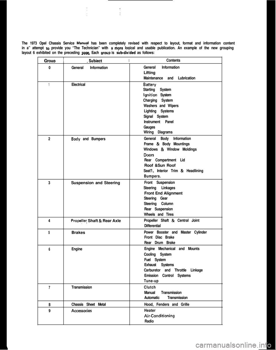
The 1973 Opel Chassis Service MayI has been completely revised with respect to layout, format and information content
in a” attempt
to provide you “The Technician” with a tiore logical and usable publication. An example of the new grouping
layout 6 exhibited on the preceding
page. Each wow is rubdivided as follows:
Grouo 1
_. _
Subiect IIContents.
0
General InformationIGeneral InformationLifting
Maintenance and Lubrication
1ElectricalBattery
Starting System
lgriition System
Charging System
Washers and Wipers
Lighting Systems
Signal SystemI
Instrument Panel
Gauges
Wiring Diagrams
2
Body and Bumpers:General Body InformationI
Frame & Body Mountings
Windows
& Window Moldings
DONS
Rear Compartment LidRoof &Sun Roof
Seat?., Interior Trim & Headlining
Bumpers.
3Suspension and Steering
Front Suspension
Steering Linkages1Front End Alignment
Steering Gear
Steering Column
Rear Suspension
Wheels and Tires
4
Propelley Shaft & Rear AxlePropeller Shaft & Central Joint
Differential
5Brakes ~Power Booster and Master Cylinder
Front Disc BrakeI
Rear Drum Brake
6EngineEngine Mechanical and Mounts
Cooling System
Fuel System
Exhaust Systems
Carburetor and Throttle Linkage
Emission Control Systems
Tune-up
7TransmissionClutch
Manual Transmission
Automatic Transmission
BChassis Sheet MetalHood, Fenders and Grille
9
Accessol;iesHeaterAirConditioning
Radio
Page 42 of 625

IGNITION SYSTEMlC-214. Rota&distributor counterclockwise slightly until
contact pbints just start to open. This must be done
very carefully or engine will not start.
5. Install distributor cap. Make sure spark plug wires
are correctly installed in distributor cap, through clip
and on spark plugs.
Finish TimingIContact boint gap
(.016” at widest gap) or dwell 50
degrees plus or minus 3 degrees should always be
checked before adjusting ignition timing.
1. Connekt timing light to No. 1 spark plug.
2. Disconnect and plug vacuum advance unit and
retard u$it hoses.
3. Connect a tachometer from distributor side of coil
to
groun$l.4. Start dngine. Set idle speed to 900 RPM.
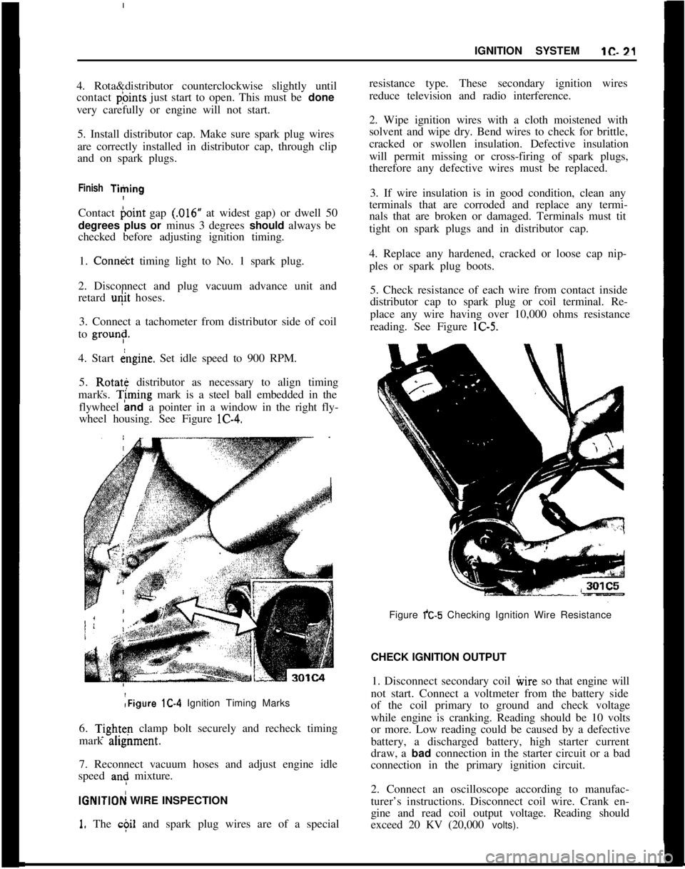
5. Rotate distributor as necessary to align timing
marks. T;ming mark is a steel ball embedded in the
flywheel and a pointer in a window in the right fly-
wheel housing. See Figure lC-4.:Figure lC-4 Ignition Timing Marks
6.
Tightq clamp bolt securely and recheck timing
mark ahgnment.
7. Reconnect vacuum hoses and adjust engine idle
speed
an: mixture.
IGNlTlOFj WIRE INSPECTION
1. The c$il and spark plug wires are of a specialresistance type. These secondary ignition wires
reduce television and radio interference.
2. Wipe ignition wires with a cloth moistened with
solvent and wipe dry. Bend wires to check for brittle,
cracked or swollen insulation. Defective insulation
will permit missing or cross-firing of spark plugs,
therefore any defective wires must be replaced.
3. If wire insulation is in good condition, clean any
terminals that are corroded and replace any termi-
nals that are broken or damaged. Terminals must tit
tight on spark plugs and in distributor cap.
4. Replace any hardened, cracked or loose cap nip-
ples or spark plug boots.
5. Check resistance of each wire from contact inside
distributor cap to spark plug or coil terminal. Re-
place any wire having over 10,000 ohms resistance
reading. See Figure lC-5.
Figure fC-5 Checking Ignition Wire Resistance
CHECK IGNITION OUTPUT
1. Disconnect secondary coil ivire so that engine will
not start. Connect a voltmeter from the battery side
of the coil primary to ground and check voltage
while engine is cranking. Reading should be 10 volts
or more. Low reading could be caused by a defective
battery, a discharged battery, high starter current
draw, a bad connection in the starter circuit or a bad
connection in the primary ignition circuit.
2. Connect an oscilloscope according to manufac-
turer’s instructions. Disconnect coil wire. Crank en-
gine and read coil output voltage. Reading should
exceed 20 KV (20,000 volts).
Page 66 of 625

LIGHTING SYSTEMSlF-45LIGHTING SYSTEMS
CONTENTS
Subject
DESCRIPTION AND OPERATION:
LightingSystems................................................................
DIAGNOSIS:MAINTENANCT AND ADJUSTMENTS:
Headlamp Aiming..............................................................
MAJOR REPAIR:
Opel 1900
- Manta
HeadlightSwitch............................................................
Fog Lamp or Heated Rear Window Switch
..........
SealBeam........................................................................
Tail Lamps........................................................................
LicensePlateLamp........................................................
FrontSideMarker..........................................................
Rear Side Marker..........................................................
Courtesy Light................................................................
DoorJamSwitch............................................................
GT
Front Turn Signal..........................................................
SealBeam........................................................................
Tail Lamps........................................................................
Side Marker......................................................................
LicensePlateLamp........................................................
Backup Lamp
..................................................................
InteriorLight....................................................................
Headlamp Switch..........................................................
DoorJamSwitch............................................................
SPECIFICATIONS:
Page No.
1 F-45
1 F-46
1 F-46
1 F-47
1 F-47
1 F-40
1 F-49
1 F-49
1 F-50
1 F-50
1 F-50lF-51lF-51lF-51
1 F-52
1 F-52
1 F-53
1 F-53
1 F-53
1 F-53
DESCRIPTION AND OPERATION
DESCRIPTION OF LIGHTING SYSTEMThe
three-baition light switch on Opel 1900 and
Manta corjtrols the headlights, taillights, parking
lights, side marker lights, instrument panel lights,
and the lic&se plate light.
When the
Qght switch knob is pulled out to the first
stop, the .pxking lights, side marker lights, the Ii-
cerise plate light, and the instrument panel lights will
light.
Pulling the knob out all the way turns the headlights
on.The instrument panel lights come on when the head-
light switch is pulled out to the first stop or pulled
out ‘all the way. The instrument panel lights are
turned off by turning the switch knob counterclock-
wise past the first detent.
Page 78 of 625

,I
IINSTRUMENT PANEL
lH- 57
/
/SubjectPage No. INSTRUMENT PANEL
CONTENTS
DESCRIPTION AND OPERATION:
Instrument Panel
- Opel 1900 - Manta. . . . . . . . . . . . . . . . . . . . . .Instrument
Panel-GT. . . . . . . . . . . . . . . . . . . . . . . . . . . . . . . . . . . . . . . . . . . . . . . . . . . . . .DIAGNOSIS:
MAINTENANCE AND ADJUSTMENTS:
MAJOR REPAIR:
Instrument Cluster Housing
- Opel 1900 - Manta . .
Windshield Wiper Switch
. , . . . . . . . . . . . . . . . . . . . . . . . . . . . . . . . . . . . . . . . . . . . .InstrumentCluster
Bulbs. . . . . . . . . . . . . . . . . . . . . . . . . . . . . . . . . . . . . . . . . . . . . . . .InstrumentCluster
Housing-GT. . . . . . . . . . . . . . . . . . . . . . . . . . . . . . . . . .Combined Switch Assemblies
. . . . . , . . . . . . . . . . . . . . . . . . . . . . . . . . . . . . . .CigarLighter
. . . . . . . . . . . . . . . . . . . . . . . . . . . . . . . . . . . . . . . , . . . . . . . . . . . . . . . . . . . . . . . . . . . . . . . .SPECIFICATIONS: (Not Applicable)
I H-57
1H-58
1H-59
1H-61
lH-61
1H-61
1H-63
1H-64
DESCF(lPTlON AND OPERATION2. The fog light toggle switch lower half is pushed in.INSTRUFENT PANEL (OPEL 1900. MANTA)
Headligl$ Switch
3. The parking lights and/or low beam headlights are
on.The thr& position light switch controls the head-
lights, @lights, parking lights, side marker lights,
license
plate light and instrument panel lights and is
located
4t the lower left on the instrument panel.
With thk switch knob pulled outward to the first
stop,
thi parking lights, side marker lights, license
plate
ligiit and instrument panel lights will light. Theinstrumdnt panel lights can be turned off by turning
the
lightSwitch knob counterclockwise past the first
detent. IThe fog lights are automatically turned off if the
ignition switch is on and the headlights are on high
beam.
Windshield Wiper Switch
The windshield wiper switch is located on the instru-ment panel to the right of the headlight switch.
By pull&g the lightswitch knob out all the way, the
headlights will also be turned on.
IBy pushing the lower half of this switch in to the first
stop, the wipers will operate at slow speed. By push-ing in to the second stop, the wipers will operate at
fast speed.
Fog
Ligh) Switch (Rallye)The fog
iight toggle switch is located in the instru-
ment cluster to the left of the temperature and fuel
gauge
cl+ster. The fog lights can be turned off at any
time by
t,he toggle switch, but can only be turned on
when: ,
Electrically Heated Rear Window Switch (If
Equipped)The heated rear
wind&v switch is located in the
instrument panel to the right of the clock opening.
1. The ignition switch is on or the engine running.
ITo operate (only possible with the engine running),
push in on the lower half of the switch. When the
rear window is being heated, the switch will
belighted.
Page 79 of 625

1 H- 581973 OPEL SERVICE MANUAL
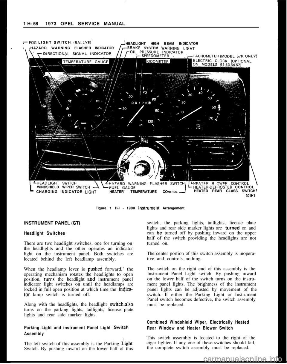
/-FOG LIGHT SWITCH IRALLYEi
\HEADLIGHT HIGH BEAM INDICATOR
-HAZARD WARNINGFLASHERINDICATORSYSTEM WARN,NGLlGHT
LWINDSHIELD WIPER SWlTCH -1 LFUEL&,UGELHEATER-DEFROSTER CONTROL
CHARGING INDICATOR LlGHTHEATER’ TEMPERATURE CONTROLHEATED REAR GLASS SWITCH1
301H1Figure 1 H-l
- 1900 lnstrumellt Arrangement
INSTRUMENT PANEL
(GT)I
Headlight SwitchesThere are two headlight switches, one for turning on
the headlights and the other operates an indicator
light on the instrument panel. Both switches are
located behind the left headlamp assembly.
When the headlamp lever is @shed forward,’ the
operating mechanism rotates the headlights to open
position, tuins the headlight and instrument panel
indicator light switches on until the headlamps are
locked in full open position at which time the indica-
tar lamp switch is turned off.
Along with the headlights, the headlight switch,also
turns on the parking lights, taillights, license plate
lights and rear side marker lights.
Parking Light and instrument Panel Light SwitCh
AssemblyThe left switch of this assembly is the Parking Light
Switch. By pushing inward on the lower half of thisswitch, the parking lights, taillights, license plate
lights and rear side marker lights are turned on and
can be turned off by pushing inward on the upper
half of the switch providing the headlights are not
turned on.
The center portion of this switch assembly is inopera-
tive and controls nothing.
The switch on the right end of this assembly is the
Instrument Panel Light switch. By pushing inward
on the lower half of the switch turns on the instru-
ment panel lights. The brightness of the instrument
panel lights can be adjusted by movement of the
switch. If either the Parking Light or Instrument
Panel switch becomes defective, the switch assembly
must be replaced.
Combined Windshield Wiper, Electrically Heated
Rear Window and Heater Blower SwitchThis switch assembly is located to the right of the
cigar lighter. If any one of these switches should fail,
the complete switch assembly must be replaced.
Page 80 of 625

/
I
IINSTRUMENT PANELlH- 59
Figure 1 H-2
- GT Instrument and Switch Arrangement
The Wihdshield Wipers have two-speed operation.
By pushing the lower half of the switch inward to the
first stop, the wipers will operate at half speed and
by deprbssing to the second stop will provide full
speed oieration. When the switch is returned to the
off posit/on, the wiper blades automatically return to
their park position.
I
The El
this optlpn. The engine must be running before
suffi-cient current can be generated to energize this circuit
even th6ugh the switch is depressed to the “ON”
position! When the window is being heated, a warm-
ing light’on the instrument panel will glow. This light
is locate? below the left ventilation inlet.
The
Heiter Blower Switch is a three position switch.
By depressing the lower half of the switch to the first
stop,
th& blower will operate at low speed. Whendepressdd to the second stop, the blower will operate
at high ipeed.
Four Way Hezrerd Warning Flasher SwitchThe
hazard warning flasher switch is located below
the heater controls in the center console. By
depress-ing the lower half of the switch, all four turn- signal
lamps flash at the same time. Although this system
makes use of the regulat turn signal system, it has a
separate feed wire to the switch which allows for its
operation even with the ignition switch and doors
locked. No vehicle should be driven with this system
in operation because of its universal meaning “This
Vehicle Is Not Moving”. To turn the system off,
simply depress the upper half of the switch.
MAJOR REPAIR
Removal of Instrument Cluster Housing Assembly.Opel 1900 Manta
Before starting any instrument panel repair, always
disconnect battery ground cable first.
I
Page 81 of 625

/
I1 H- 601973 OPEL SEW& MANUAL
1. Remove headlight switch button by depressing
retaining clip on shaft and pulling back on switch
knob. See Figure lH-3.
Figure 1 H-5
- Removing Cluster Screws
Figure lH-3
- Removing Headlight Switch Knob,
2. Remove two (2) plugs on cluster panel. See FigurelH-4.301H6
-Figure 1 H-4 Removing Plugs
3. Remove two (2) sheet metal screws behind plugs
on cluster. See Figure lH-5.
4. Pull off heater control knobs toward front.
j5. On top, carefully pull instrument ‘trim plate
:to-wards steering wheel and remove plate.
6. Remove two screws for lower housing
attach&t.See Figure lH-6.Figure 1 H-6 Lower Housing Attaching Screws
7. Disconnect speed0 cable at cluster by turning cou-
pling counterclockwise.
8. If equipped, pull heated rear window or fog lamp
switch out of instrument housing and disconnect
wires from switches.
9. Pull cluster right and left sides partially out and
disconnect wires on back of cluster. See Figure lH-7.
Installation
1.
P&e instrument cluster in position and connect
wires on back of cluster.
2. Pull fog light or heated back glass switch wires
into opening, if equipped, and connect wires and
replace switch.
3. Connect two screws on lower housing attachment.
Page 124 of 625

GROUP 2
[I
L
RnnVI----.
anlnIT\..YI-
BUMPERSII-
L
L
Section
2A
2B
2C
2D
2E
2F
2G 2H
Title
General Information Frame and Body Mountings
. . . . . . . . . . . . . . . . . . . .
Windows and Window
Moldings
Doors
_................................
Rear Compartment Lid
Roof and Sun Roof
Seats, Interior Trim and Headlining
Bumpers
. . . . . . . . . . . . . . . . . . . . . . . . . . .
Page No.
2A- 2
2B- 6
2c- 9
2D-13
2E-22
2F-24
26-33
2H-38
Page 132 of 625

WINDOWS AND WINDOW MOLDINGS2c-9WINDOWS AND WINDOW MOLDINGS
CONTENTS
Subject
DESCRIPTION AND OPERATION: (Not Applicable)
DIAGNOSIS: (Not Applicable)
MAINTENANCE AND ADJUSTMENTS: (Not
Applicable)
MAJOR REPAIR:
Removal and Installation
Windshield
RevealMolding. . . . . . . . . . . . . . . . . . . . . . . . . . . . . . . . . . . . . . . .Windshield
andBackWindow. . . . . . . . . . . . . . . . . . . . . . . . . . . . . . . . . .
DoorWindow. . . . . . . . . . . . . . . . . . . . . . . . . . . . . . . . . . . . . . . . . . . . . . . . . . . . . . . . . . . . . . . . . .Rear Quarter Window Molding
. . . . . . . . . . . . . . . . . . . . . . . . . . . . . . . .Rear Quarter Window
-1900 -Manta. . . . . . . . . . . . . . . . . .RearQuarterWindow
-GT. . . . . . . . . . . . . . . . . . . . . . . . . . . . . . . . . . . . . . . .
RearQuarterWindowLock. . . . . . . . . . . . . . . . . . . . . . . . . . . . . . . . . . . . . . . .SPECIFICATIONS: (Not Applicable)Page No.
2c- 9
2c-10
2c-11
2c-11
2c-12
2c-12
2c-12
MAJOR REPAIR
REMOVAL AND INSTALLATION OF WINDSHIELD3. With Tools J-2 1828 and J-2 1549, insert new reveal
REVEAL MOLDINGmolding and install escutcheon.
1. Remove reveal molding escutcheon. Starting at
one end, pull molding out of rubber channel. See
Figure
2C-2.Figure ZC-2 Removing Reveal Molding
Figure ZC-3 Pushing Windshield Out 2. Prior to installation, place molding in water and
heat up to approximately 113
- 122 degrees F.
Page 133 of 625

2c-101973 OPEL SERVICE MANUAL
REMOVAL AND INSTALLATION OF WINDSHIELD
OR BACK WINDOW-WINDSHIELD SHOWN
1. Flap back windshield wiper arms,
2. Beginning at one end, pull molding out of rubber
channel.
3. Beginning at one corner, push out windshield
together with rubber channel. See Figure 2C-3.4. Place new windshield on glass holding fixture and
tit new rubber channel. See Figure
2C-4.5. Insert a thick string into large sealing lip of rubber
channel so that both ends are crossed at bottom cen-
ter of windshield. See Figure
2C-5.6. With a sealer gun, coat outside of pinchweld flange
with sealing compound. See Figure
2C-6./’
Figure
2C-4 Fitting Rubber Channel on Windshield
Figure
2C-5 String Inserted Into Rubber ChannelFigure 2C-6 Applying Sealer on Pinchweld Flange
7. Place windshield in body opening and, with in-
serted string, pull rubber channel lip over pinchweld
flange, always tapping windshield from outside with
a striking pad. See Figure
2C-7.Figure
2C-7 Pulling Rubber Channel Lip Over
Pinchweld Flange