checking oil OPEL GT-R 1973 Service Manual
[x] Cancel search | Manufacturer: OPEL, Model Year: 1973, Model line: GT-R, Model: OPEL GT-R 1973Pages: 625, PDF Size: 17.22 MB
Page 20 of 625
LUBRICATION AND MAINTENANCE OC-11
Throttle Linkage
Check for damaged or missing parts, interference or
binding. Any deficiencies should be corrected with-
out delay.
Headlights
Check for proper aim. Correct as necessary. More
frequent checks should be made if oncoming motor-
ists signal when you are already using your low
beams, or if illumination of the area ‘ahead seems
inadequate.
Underbody
In geographic areas using a heavy concentration of
road salt or other corrosive materials for snow re-
moval or road dust control, flush and inspect the
complete under side of the car at least once each
year, preferably after a winter’s exposure. Particular
attention should be given to cleaning out underbody
members where dirt and other foreign materials may
have collected.
EMISSION CONTROL MAINTENANCE
Thermostatically Controlled Air Cleaner
Inspect installation to make certain that all hoses and
ducts are connected and correctly installed. Also,
check valve for proper operation.
Carburetor Choke
Check choke mechanism for free operation. A bind-
ing condition may have developed from petroleum
gum formation on the choke shaft or from overtight-
ening of air cleaner clamp. Also check electric choke
terminal connections and fuse.
Timing, Dwell and Distributor
Adjust timing and dwell accurately as outlined under
Tune-Up in Group 6 at the first 4 months or 6,ooOmiles of operation, then at 12 month or
12,OQO mile
intervals. Adjustments must be made with test equip-
ment known to be accurate.
Replace distributor points every 12 months or 12,000
miles and carefully clean and inspect the complete
distributor cap to prevent misfiring and deteriora-
tion.
Carburetor and Idle
SpeedTorque carburetor attaching bolts and/or nuts to 12
ft.lbs. to compensate for compression of gasket atiirst 4 months or 6,000 miles of vehicle operation.Adjust idle speed to specifications with known accu-
rate equipment.
Proper functioning of the carburetor is particularly
essential to control of emissions. Correct mixtures
for emission compliance and idle quality have been
preset by Opel. Plastic idle mixture limiters have
been installed on the idle mixture screw, idle air
screw, and throttle stop screw to preclude unauthor-
ized adjustment. The plastic caps on the idle mixture
screw and the idle adjustment screw must be
removed to perform an idle speed adjustment. The
plastic cap on the throttle stop screw is not to be
removed unless some major carburetor repair or re-
placement which affects the throttle stop screw ad-
justment has been necessary.
Carburetor Fuel Inlet Filter
Replace filter at 12 month or
12,OCO mile intervals
or more often if clogged.
Spark Plugs
Replace at
6,ooO mile intervals when operating with
leaded fuels or at 12,000 mile intervals when using
unleaded fuels. Use of leaded fuels results in lead
deposits on spark plugs and can cause misfiring at
mileages less than
12,OilO miles. Where misfiring oc-
curs prior to
6,ooO miles, spark plugs in good condi-
tion can often be cleaned, tested and reinstalled in an
engine with acceptable results.
Spark Plug Wires
Inspect spark plug wires for evidence of checking or
cracking of exterior insulation and tight fit in the
distributor cap and at the spark plugs. Exterior of
wires should be cleaned, any evidence of corrosion
on ends removed and wire replace if deteriorated.
Positive Crankcase Ventilation System
The PCV metered orifice should be cleaned at 12,000
mile intervals under normal use, and at 6,000 mile
intervals when the vehicle is used under the follow-
ing conditions: driving in dusty conditions, extensive
idling, trailer pulling and short trip operation at
freezing temperatures (engine not thoroughly
warmed-up).
Evaporation Control System
Check all fuel and vapor lines and hoses for proper
connections and correct routing as well as condition.
Remove canister and check for cracks or damage.
Replace damaged or deteriorated parts as necessary.
Replace filter in open end of canister at 24month/24,000 mile intervals.
Page 31 of 625
1 B- 101973 OPEL SERVICE #MANUAL
STARTlhG SYSTEM
/
ALL
MODEILS
CONTENTS
Subject
DESCRIPTION AND OPERATION:
Starting SystemDescription
. . . . . . . . . . . . . . . . . . . . . . . . . . . . . . . . . . . . \
. . . . . .
DIAGNOSIS:
Starting System Diagnosis,
. . . . . . . . . . . . . . . . . , . . . . . . . . . . . . . . . . . . \
. . . . . . . .
MAINTENANCE AND ADJUSTMENTS:Starting System
Checks. . . . . . . . . . . . . . . . . . . . . . . . . . . . . . . . . . . . \
. . . . . . . . . . . . . .
MAJOR REPAIR:
Removal. . . . . . . . . . . . . . . . . . . . . . . . . . . . . . . . . . . . \
. . . . . . . . . . . . . . . . . ., . . . . . . . . . . . . . . . . . . . . . . . . . .
Disassembly. . . . . . . . . . . . . . . . . . . . . . . . . . . . . . . a.... . . . . . . . . . . . . . . . . . . . . . . . . . . . . . . . . . . . .\
CleaningandInspecting Parts. . . . . . . . . . . . . . . . . . . . . . . . . . . . . . . . . . . . \
. .
Replacing Field Coils. . . . . . . . . . . , . . . . . . . . . . . . . . . . . . . . . . . . \
. . . . . . . . . . . . . . . . . . . .
Checking and Replacing Brushes. . . . . . . . . . . . . . . . . . . . . . . . . . . . . . . .
Replacing Bushings. . . . . . . . . . . . . . . . . . . . . . . . . . . . . . . , . . . . \
. . . . . . . . . . . . . . . . . . . . . .
Assembly. . . . . . . . . . . . . . . . . . . . . . . . . . . . . . . . . . . . \
. . . . . . . . . . . . . . . . . . . . . . . . . . . . . . . . . . . . \
. . . . . .
Installation. . . . . . . . . . . . . . . . . . . . . . . . . . . . . . . . . . . . \
. . . . . . . . . . . . . . . . . . . . . . . . . . . . . . . . . . . . \
. . . .
SPECIFICATIONS:
Starter Specifications
. . . . , . , . . . . . . . . . . . . . . . . . . . . . . . . . . . . . . . . . . . . . . . . . . . . . . .
Page No.
lB-10
16-10
18-12
18-13
18-13
18-14
18-14
16-15
18-16
lB-16
18-17
18-17
DESCRIPTION AND OPERATION
STARTING SYSTEM DESCRlPTlqN
The new Delco Remy starter for 1973 is a brush-
type series wound electric motor equipped with an
overrunning clutch and operated by a
soienoid. The
field frame is enclosed by the commutator end frame
and the drive housing and carries the pole shoes and
the
field coils. The armature has a spline on the drive
end which carries the over-running clutch and pinion
assembly. The armature shaft is supported in
sin-
tered bronze bushings in the commtitator end frame
and the drive end housing. These bushings are
packed with lubricant during initial assembly
and
TROUBLE DIAGNOSIS ’
STARTING SYSTEM DIAGNOSIS/
require no additional lubrication between overhaul
periods.
As the starter is operated by turning the ignition
switch on the instrument panel, the shift lever is
moved against spring tension. By means of the guide
ring, the shift lever moves the pinion into mesh with
the flywheel ring gear.
After the pinion meshes with the flywheel ring gear
teeth, the solenoid contact disc closes the circuit and
the engine is cranked. When the engine starts, the
speed of the rotating flywheel causes the pinion to
over-run the clutch and armature. The pinion con-
tinues to be engaged as long as the shift lever is kept
in the cranking position.
In case of cranking motor breakdown, it should be kept in mind that the
relevant cause(s) for the trouble may not only lie in the cranking mot\
or itself
Page 35 of 625
lB- 14 1973 OPEL SERVICE MANUAL !
6. Remove shift lever shaft and: lift armature aid
shift lever assembly.
7. Drive back retaining ring on armature shaft. See
Figure
lB-5.
8. Take the lock ring, retaining ring, and
over&-
ning clutch and pinion off armature shaft. Cheqk
groove in shaft for burrs and remove with a soft tile.
Cleaning and Inspecting Parts
1. Clean and check all parts. Replace defective parts.
2. Turn down worn or burnt
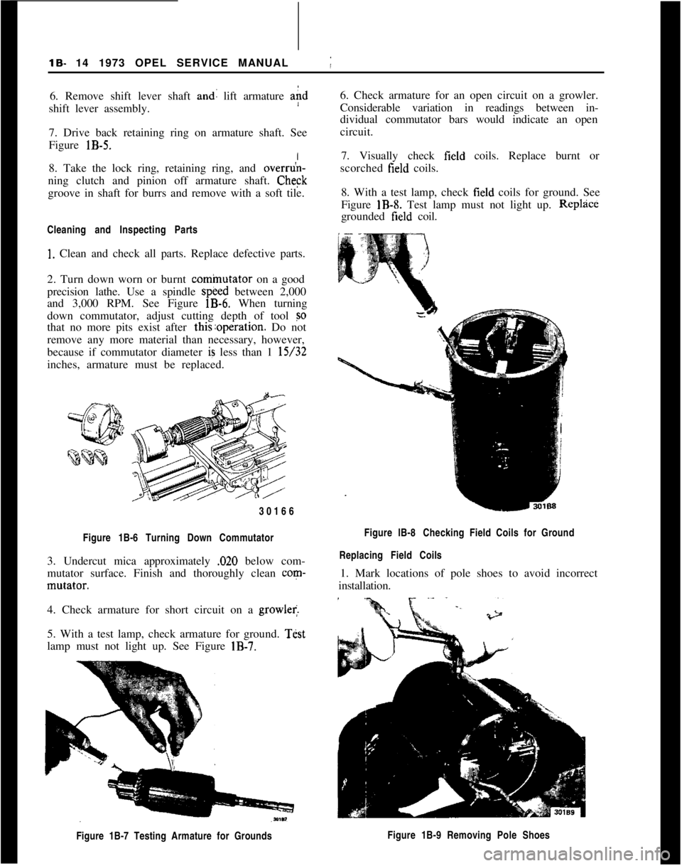
cominutator on a good
precision lathe. Use a spindle
speed between 2,000
and 3,000 RPM. See Figure
lB-6. When turning
down commutator, adjust cutting depth of tool
so
that no more pits exist after this:operation. Do not
remove any more material than necessary, however,
because if commutator diameter
is less than 1 15/32
inches, armature must be replaced.
30166
Figure 1B-6 Turning Down Commutator
3. Undercut mica approximately ,020 below com-
mutator surface. Finish and thoroughly clean
corn-
mutator.
I
4. Check armature for short circuit on a
growler.
5. With a test lamp, check armature for ground.
Test
lamp must not light up. See Figure
IB-7.
Figure 1B-7 Testing Armature for Grounds
j
6. Check armature for an open circuit on a growler.
Considerable variation in readings between in-
dividual commutator bars would indicate an open
circuit.
7. Visually check
field coils. Replace burnt or
scorched
field coils.
8. With a test lamp, check
field coils for ground. See
Figure
IB-8. Test lamp must not light up. Replzice
grounded field coil.
Figure lB-8 Checking Field Coils for Ground
Replacing Field Coils
1. Mark locations of pole shoes to avoid incorrect
installation.
Figure 1B-9 Removing Pole Shoes
Page 36 of 625
STARTING SYSTEMlS- 15
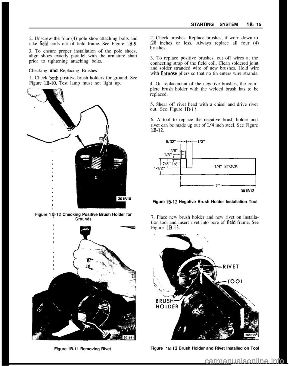
2. Unscrew the four (4) pole shoe attaching bolts and
take
field coils out of field frame. See Figure lB-9.
3. To ensure proper installation of the pole shoes,
align shoes exactly parallel with the armature shaft
prior to tightening attaching bolts.
Checking
a’nd Replacing Brushes
1. Check
b&h positive brush holders for ground. See
Figure
lB-,lO. Test lamp must not light up.
Figure 1g-10 Checking Positive Brush Holder forGrounds
2. Check brushes. Replace brushes, if worn down to
.28 inches or less. Always replace all four (4)
brushes.
3. To replace positive brushes, cut off wires at the
connecting strap of the field coil. Clean soldered joint
and solder stranded wire of new brushes. Hold wire
with
flatnose pliers so that no tin enters wire strands.
4. On replacement of the negative brushes, the com-
plete brush holder with the welded brush has to be
replaced. 5. Shear off rivet head with a chisel and drive rivet
out. See Figure
lB-11.
6. A tool to replace the negative brush holder and
rivet can be made up out of
l/4 inch steel. See Figure
Figure 18.12 Negative Brush Holder Installation Tool
7. Place new brush holder and new rivet on installa-
tion tool and insert rivet into bore of
field frame. See
Figure
lB-13.
Figure 1B-11 Removing Rivet Figure 18-13
Brush Holder and Rivet Installed on Tool
Page 42 of 625
IGNITION SYSTEMlC-214. Rota&distributor counterclockwise slightly until
contact pbints just start to open. This must be done
very carefully or engine will not start.
5. Install distributor cap. Make sure spark plug wires
are correctly installed in distributor cap, through clip
and on spark plugs.
Finish TimingIContact boint gap
(.016” at widest gap) or dwell 50
degrees plus or minus 3 degrees should always be
checked before adjusting ignition timing.
1. Connekt timing light to No. 1 spark plug.
2. Disconnect and plug vacuum advance unit and
retard u$it hoses.
3. Connect a tachometer from distributor side of coil
to
groun$l.4. Start dngine. Set idle speed to 900 RPM.
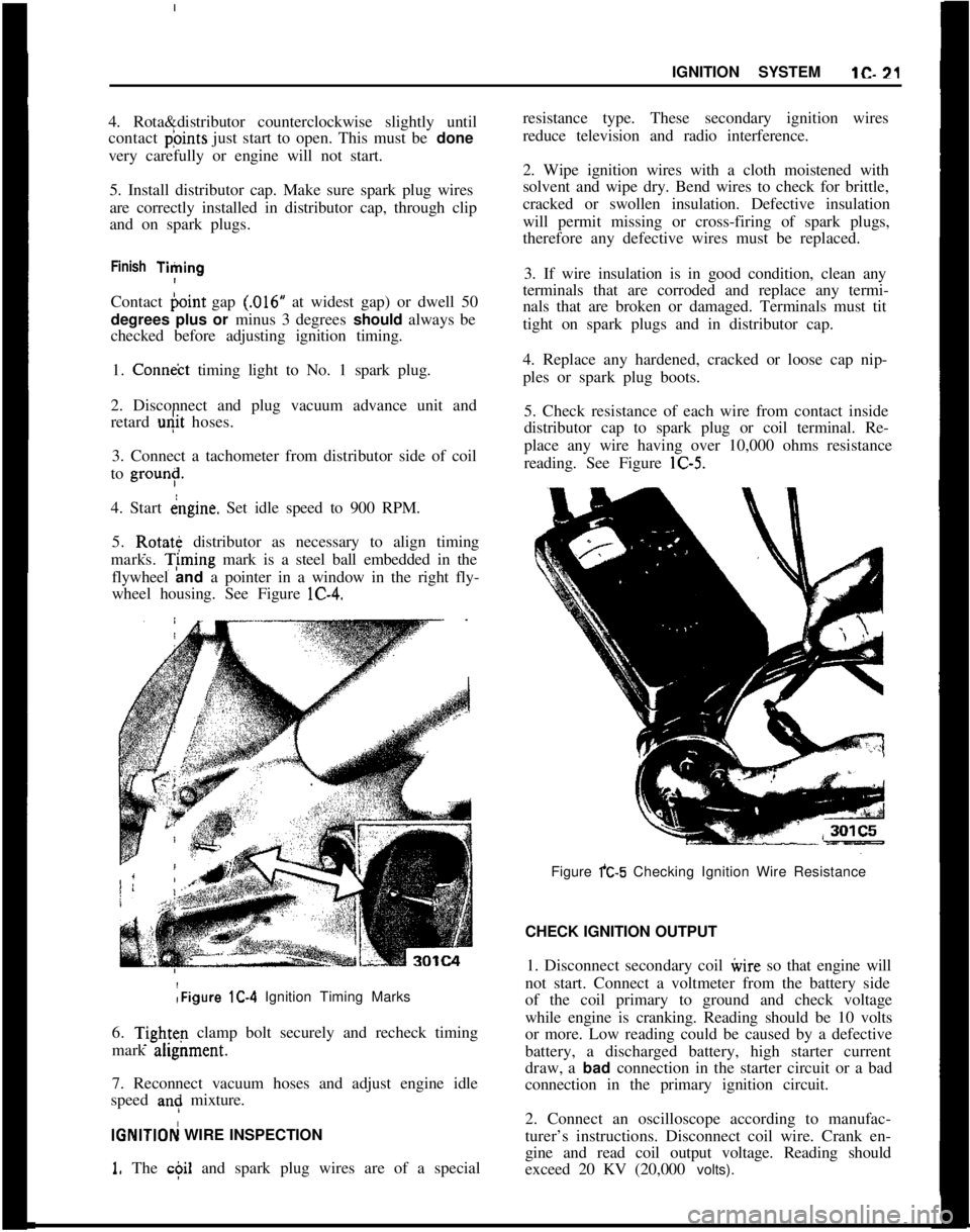
5. Rotate distributor as necessary to align timing
marks. T;ming mark is a steel ball embedded in the
flywheel and a pointer in a window in the right fly-
wheel housing. See Figure lC-4.:Figure lC-4 Ignition Timing Marks
6.
Tightq clamp bolt securely and recheck timing
mark ahgnment.
7. Reconnect vacuum hoses and adjust engine idle
speed
an: mixture.
IGNlTlOFj WIRE INSPECTION
1. The c$il and spark plug wires are of a specialresistance type. These secondary ignition wires
reduce television and radio interference.
2. Wipe ignition wires with a cloth moistened with
solvent and wipe dry. Bend wires to check for brittle,
cracked or swollen insulation. Defective insulation
will permit missing or cross-firing of spark plugs,
therefore any defective wires must be replaced.
3. If wire insulation is in good condition, clean any
terminals that are corroded and replace any termi-
nals that are broken or damaged. Terminals must tit
tight on spark plugs and in distributor cap.
4. Replace any hardened, cracked or loose cap nip-
ples or spark plug boots.
5. Check resistance of each wire from contact inside
distributor cap to spark plug or coil terminal. Re-
place any wire having over 10,000 ohms resistance
reading. See Figure lC-5.
Figure fC-5 Checking Ignition Wire Resistance
CHECK IGNITION OUTPUT
1. Disconnect secondary coil ivire so that engine will
not start. Connect a voltmeter from the battery side
of the coil primary to ground and check voltage
while engine is cranking. Reading should be 10 volts
or more. Low reading could be caused by a defective
battery, a discharged battery, high starter current
draw, a bad connection in the starter circuit or a bad
connection in the primary ignition circuit.
2. Connect an oscilloscope according to manufac-
turer’s instructions. Disconnect coil wire. Crank en-
gine and read coil output voltage. Reading should
exceed 20 KV (20,000 volts).
Page 67 of 625
1F. 46 1973 OPEL SERVICE MANUAL
’
/
Headlight High-Low Beam Control and Passing:
SignalI
When the headlights have been switched on, high
and low beam selection is made by raising the direc-
tional signal lever toward steering wheel. Each
ti&the lever is raised, beam position, will change.
When the headlights are not on, a flashing headlight
signal may be given by raising and lotiering the di-
rectional signal lever. With the headlights on and
inlow beam position, raising and lowering the direc-
tional signal lever will also cause the headlights to
flash.
Fog Light SwitchAll Rallye models are equipped with two white f?g
lights mounted below the front bumper.
The fog light toggle switch is located on the
insty-ment cluster to the left of the temperature and
fuelgauge cluster.
/
The fog lights can be turned off at any time by the
toggle switch, but can only be tyrned on when: :
1. The ignition switch on or the
?gine running.!
2. The fog light toggle switch lower half is pushed
in.3. The parking lights and/or low beam headlights
are
OKThe fog lights are automatically turned off if the
ignition switch is on and the headlights are switched
to high beam position.
Courtesy LightThe courtesy light illuminates the interior of the Car
when any door is opened. The courtesy light can also
be turned on with all doors closed by tilting the l&s.
GT Headlamp MechanismThe concealed headlamps are moved mechanically.
Pushing actuating lever on left side of console opens
headlamps and pulling lever closes headlamps. Two
(2) meshing gear segments convert the movement, of
the lever to a rotation of 180 degrees. The pivots of
the headlamps lie below the centerline so that with
headlamps in closed position, the headlamp housing
is flush with front sheet metal. Refer to Group 110,
Section “F”, for service procedures on the GT head-
lamp mechanism.
A white indicator lamp in the instrument panel lights
if the headlamps are not completely opened lorclosed The switches of the headlamp electrical sys-
tem are located behind the left headlamp operating,
mechanism.
MAINTENANCE AND ADJUSTMENTSHEADLAMP AIMING
The headlamps must be properly aimed in order to
obtain maximum road illumination and safety that
has been built into the headlighting equipment. With
the Guide T-3 type sealed beam units, proper aiming
is even more important because the increased range
and power of this lamp make even slight variations
from recommended aiming hazardous to approach-
ing motorists. The headlamps must be checked for
proper aim whenever a sealed beam unit is replaced
and after an adjustment or repairs of the front end
sheet metal assembly.
Regardless of method used for checking headlamp
aim, car must be at normal weight, that is, with gas,
oil, water, and spare tire. Tires must be uniformly
inflated to specified pressure. If car will regularly
carry an unusual load in rear compartment, or a
trailer, these loads should be on car when headlamps
are checked. Some States have special requirements
for headlamp aiming adjustment, and these require-
ments should be known and observed.
Horizontal and vertical aiming of each seal beam
unit is provided by two adjusting screws which move
the mounting ring in the body against the tension of
the coil spring. There is no adjustment for focus,
since the sealed beam unit is set for proper focus
during manufacturing assembly.
MAJOR REPAIRHEADLIGHT SWITCH
- OPEL 1900. MANTA
Removal1. Remove instrument cluster cover panel. See Sec-
tion H.
2. Compress retaining springs and pull switch out.
See Figure 1 F-
1.3. Pull multiple socket off switch.
Installation
1: Plug multiple socket in switch and push switch in
panel until clips lock in place.
2. Replace instrument cover and secure with two (2)
screws.
Page 253 of 625
48. 221973 OPEL SERVICE MANUAL
9. Position
case assembly and outer races in the car-
rier. Use a soft-faced hammer to drive the case into
the carrier until the side bearing outer races bottom
in their bores.
10. Install side bearing caps in their original location
and torque the bolts to 33
lb.ft.IN. LB. TORQUL
11. Rotate case assembly several times to seat the
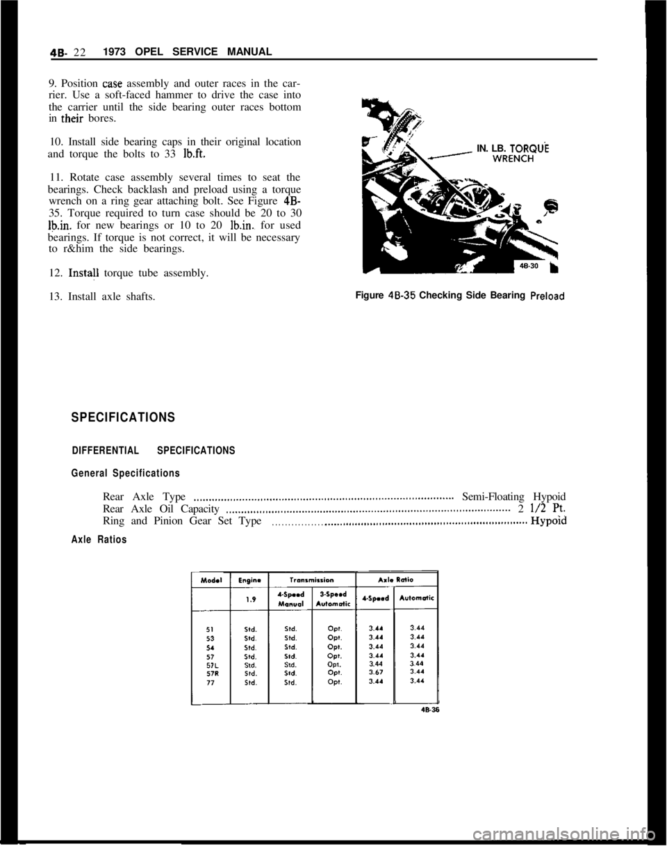
bearings. Check backlash and preload using a torque
wrench on a ring gear attaching bolt. See Figure 4B-
35. Torque required to turn case should be 20 to 30
Ib.in. for new bearings or 10 to 20 lb.in., for used
bearings. If torque is not correct, it will be necessary
to r&him the side bearings.
12. Insta!l torque tube assembly.
13. Install axle shafts.Figure 48.35 Checking Side Bearing
Preload
SPECIFICATIONS
DIFFERENTIAL SPECIFICATIONS
General SpecificationsRear Axle Type
.,,...,,,...,,_...._..,,...,,,...,,,....,,.,...,,.,,...,,..,,,........................ Semi-Floating Hypoid
Rear Axle Oil Capacity
..____,,...,,,...,.,..,............,,..,,..,,................................................. 2 l/2 7’.Ring and Pinion Gear Set Type
. . . . . . . . . . . . . . . . . .._................................................................Hypold
Axle Ratios
Page 274 of 625

DISC BRAKES5B- 15
ConditionPossible Cause
2. Binding brake pedal
mechanism.Correction
2. Check and lubricate, ifnecessary.3. Corroded caliper
assembly.3. Clean and lubricate.
MAINTENANCE AND ADJUSTMENTSDISC BRAKE MAINTENANCE
Checking Brake Fluid Level
The brake fluid level in the brake fluid container
must be checked during predelivery inspection, then
every 3,000 miles during inspection and preventive
maintenance servicing.
The brake fluid level must not be higher than the
inscription “MAX” and must be at least up to
“MIN”. Replenish brake fluid, if necessary.
Because of the relatively large brake caliper bore
cross section and the self-adjustment of the disc
brakes, resulting in a greater piston travel to compen-
sate for friction pad wear, the brake fluid level drops
faster than in fluid containers for drum brakes with
their smaller wheel brake cylinders. For this reason
pay special attention to the fluid level in the brake
fluid container.
Drop of brake fluid level can be due to friction pad
wear and may not be due to leakage in the braking
system.On loss of brake fluid due to leakage, the brake sys-
tem must be checked thoroughly.
Friction Pad Adjustment
Friction pad adjustment is not necessary on the front
wheel disc brakes as this is done automatically by the
pistons in the brake calipers.
Lubricating Front Wheel Bearings
When removing one or both brake discs, check lu-
brication of front wheel bearings and the cavity of
the wheel hub and replenish if necessary (see operat-
ion
“Removing and Reinstalling Brake Disc”).
When carrying out other work on disc brakes which
does not necessitate the removal and installation of
the brake disc, lubricating wheel bearings is not
necessary.Checking Disc Brake Friction Pads for Wear
Whenever a disc brake equipped car is in for periodic
service, while the car is raised, the friction pads in
both brake calipers should be checked for wear by
making a simple measurement. Worn or oily friction
pads must be replaced.
Measure friction pad wear as follows:
1. Remove friction pads.
2. Using a one-inch micrometer, measure the thick-
ness of the pad and friction plate. See Figure
5B-23.Figure 58-23 Checking Brake Friction Pad Thickness
3. If any one of the four measurements is less than
-.280, replace all four friction pads. (Partial replace-
ment of friction pads would cause unequal braking.)
Removal and Installation of Friction Pads
1. Raise car and remove front wheels.
2. Drive dowel pins out of brake calipers toward
center of car. See Figure
5B-24. Dowel pins must be
driven inward because they are secured by enlarge
fluted inner ends.
3. Remove friction pads from brake calipers. See
Figure
5B-25.
Page 307 of 625
6A- 161973 OPEL SERVICE MANUALInspection of Connecting Rod Bearings and
Crankshaft JournalsRemove oil pan.
After removal of oil pan, disconnect two connecting
rods at a time from crankshaft and inspect the bear-
ings and crankpin journals. While,tuming crankshaft
it is necessary to
t&porarily reconnect the rods to
crankshaft to avoid possibility of damaging the jour-
nals through contact with loose rods.
If connecting rod bearings are chipped or scored they
should be replaced. If bearings
are in good physical
condition check for proper clearance on crankpins as
described under, checking clear$nce and selecting
replacement connecting rod beartngs.
If crankpin journals are scored or ridged, the crank-
shaft must be replaced, or reground for undersize
bearings, to insure satisfactory life of connecting rod
bearings. Slight roughness may be polished out withfine grit polishing cloth thoroughly wetted with en-
gine oil. Burrs may be honed off with a fine oil stone.
Use an outside micrometer to check crankpins for
out- of-round. If crankpins are mpre than
,002” out-
of- round, satisfactory life of new ,bearings cannot be
expected.
Checking Clearance and Selecting Replacement
Connecting Rod BearingsService bearings are furnished in standard size and
several undersizes. The clearance of connecting rod
(and crankshaft) bearings may be checked by use of
Plastigage, Type PG-1 (green), or equivalent, which
is soluble in oil.
1. Remove connecting rod cap with bearing shell.
Wipe off oil from bearing and crankpin journal, also
blow oil out of hole in crankshaft.
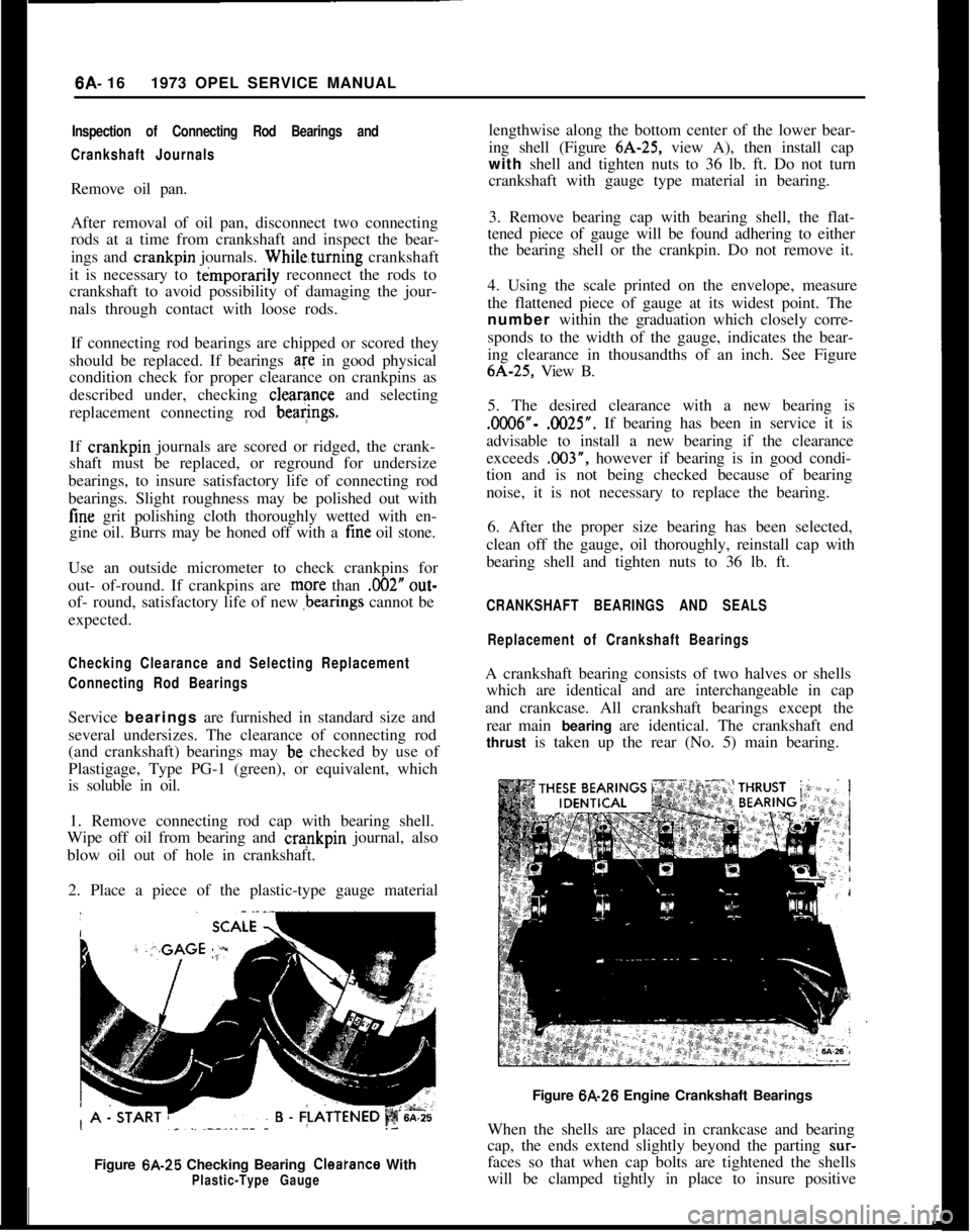
2. Place a piece of the plastic-type gauge material
Figure 6A-25 Checking Bearing
Cleatance WithPlastic-Type Gaugelengthwise along the bottom center of the lower bear-
ing shell (Figure 6A-25, view A), then install cap
with shell and tighten nuts to 36 lb. ft. Do not turn
crankshaft with gauge type material in bearing.
3. Remove bearing cap with bearing shell, the flat-
tened piece of gauge will be found adhering to either
the bearing shell or the crankpin. Do not remove it.
4. Using the scale printed on the envelope, measure
the flattened piece of gauge at its widest point. The
number within the graduation which closely corre-
sponds to the width of the gauge, indicates the bear-
ing clearance in thousandths of an inch. See Figure6A-25, View B.
5. The desired clearance with a new bearing is.0006”- .0025”. If bearing has been in service it is
advisable to install a new bearing if the clearance
exceeds .003”, however if bearing is in good condi-
tion and is not being checked because of bearing
noise, it is not necessary to replace the bearing.
6. After the proper size bearing has been selected,
clean off the gauge, oil thoroughly, reinstall cap with
bearing shell and tighten nuts to 36 lb. ft.
CRANKSHAFT BEARINGS AND SEALS
Replacement of Crankshaft BearingsA crankshaft bearing consists of two halves or shells
which are identical and are interchangeable in cap
and crankcase. All crankshaft bearings except the
rear main bearing are identical. The crankshaft end
thrust is taken up the rear (No. 5) main bearing.
Figure 6A-26 Engine Crankshaft Bearings
When the shells are placed in crankcase and bearing
cap, the ends extend slightly beyond the parting
sur-faces so that when cap bolts are tightened the shells
will be clamped tightly in place to insure positive
Page 308 of 625
ENGINE MECHANICAL AND MOUNTS6A- 17
seating and to prevent turning.The ends of she//s
must never be tiled flush with parting surface of
crankcase or bearing cap.Crankshaft bearings are the precision type which do
not require reaming to size. Shims are not provided
for adjustment since worn bearings are readily re-
placed with new bearings of proper size. Bearings for
service replacement are furnished in standard size
and undersizes. Under no circumstances should
crankshaft bearing caps be tiIed to adjust for wear in
old bearing.After removal of oil pan, pipe and screen assembly,
perform the following removal, inspection and in-
stallation operations on each crankshaft bearing in
turn so that the crankshaft will be well supported by
the other bearings.
If crankshaft has been removed to check straightness
the following procedure is suggested. Rest crank-
shaft on “V-blocks” at number one and number live
main bearing journals. Check indicator runout at
No. 3 main bearing journal. Total indicator reading
should not exceed
.C012”.1. Since any service condition which affects the
crankshaft bearings may also affect the connecting
rod bearings, it is advisable to inspect connecting rod
bearings
first. If crankpins are worn to the extent
that crankshaft should be replaced or reground, re-
placement of crankshaft bearings only will not be
satisfactory.
If replacement of cylinder block or crankshaft is re-
quired, always check main bearing clearance with
plastic-type gauge to obtain specified limits.
2. Remove one bearing cap, then clean and inspect
lower bearing shell and the crankshaft journal. If
journal surface is scored or ridged, the crankshaft
must be replaced or reground to insure satisfactory
operation with new bearings. Slight roughness may
be polished out with tine grit polishing cloth
thoroughly wetted with engine oil, and burrs may be
honed off with a tine stone.
3. If condition of lower bearing shell and crankshaft
journal is satisfactory, check the bearing clearance
with a plastic-type gauge.
4. When checking a crankshaft bearing with plastic-
type gauging material, turn crankshaft so that oil
hole is up to avoid dripping of oil on the gauge
material. Place paper shims in lower halves of adja-
cent bearings and tighten cap bolts to take the weight
of crankshaft
off the lower shell of beating being
checked.5. If bearing clearance exceeds
.C03”, it is advisable
to install a new bearing; however, if bearing is in
good condition and is not being checked because ofbearing noise, it is not necessary to replace the bear-
ing.6. Loosen all crankshaft bearing cap bolts
l/2 turn,
and remove cap of bearing to be replaced.
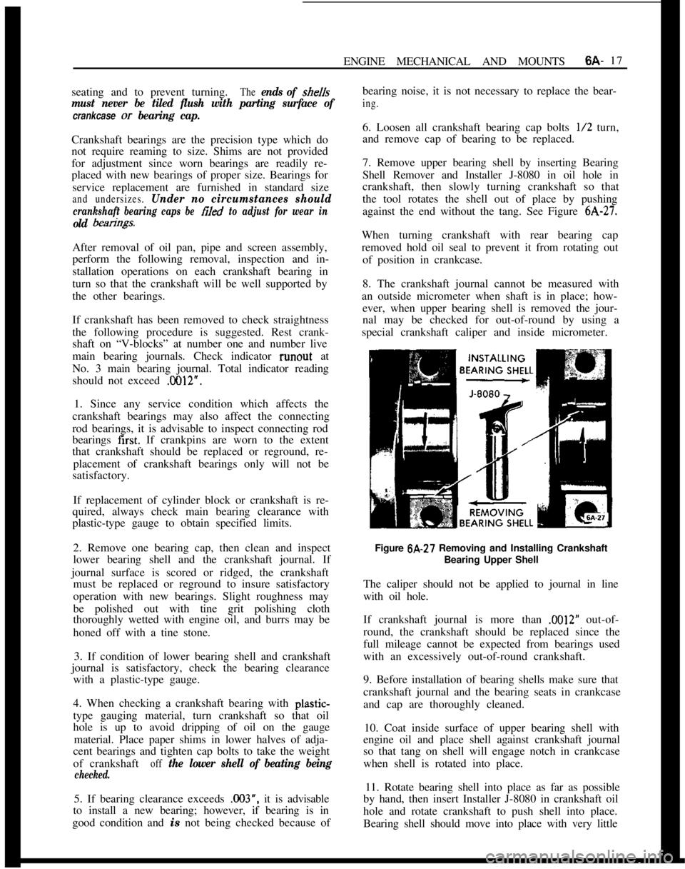
7. Remove upper bearing shell by inserting Bearing
Shell Remover and Installer J-8080 in oil hole in
crankshaft, then slowly turning crankshaft so that
the tool rotates the shell out of place by pushing
against the end without the tang. See Figure
6A-27.When turning crankshaft with rear bearing cap
removed hold oil seal to prevent it from rotating out
of position in crankcase.
8. The crankshaft journal cannot be measured with
an outside micrometer when shaft is in place; how-
ever, when upper bearing shell is removed the jour-
nal may be checked for out-of-round by using a
special crankshaft caliper and inside micrometer.
Figure 6A-27 Removing and Installing Crankshaft
Bearing Upper Shell
The caliper should not be applied to journal in line
with oil hole.
If crankshaft journal is more than
.M)12” out-of-
round, the crankshaft should be replaced since the
full mileage cannot be expected from bearings used
with an excessively out-of-round crankshaft.
9. Before installation of bearing shells make sure that
crankshaft journal and the bearing seats in crankcase
and cap are thoroughly cleaned.
10. Coat inside surface of upper bearing shell with
engine oil and place shell against crankshaft journal
so that tang on shell will engage notch in crankcase
when shell is rotated into place.
11. Rotate bearing shell into place as far as possible
by hand, then insert Installer J-8080 in crankshaft oil
hole and rotate crankshaft to push shell into place.
Bearing shell should move into place with very little