headlights OPEL GT-R 1973 Service Manual
[x] Cancel search | Manufacturer: OPEL, Model Year: 1973, Model line: GT-R, Model: OPEL GT-R 1973Pages: 625, PDF Size: 17.22 MB
Page 20 of 625
LUBRICATION AND MAINTENANCE OC-11
Throttle Linkage
Check for damaged or missing parts, interference or
binding. Any deficiencies should be corrected with-
out delay.
Headlights
Check for proper aim. Correct as necessary. More
frequent checks should be made if oncoming motor-
ists signal when you are already using your low
beams, or if illumination of the area ‘ahead seems
inadequate.
Underbody
In geographic areas using a heavy concentration of
road salt or other corrosive materials for snow re-
moval or road dust control, flush and inspect the
complete under side of the car at least once each
year, preferably after a winter’s exposure. Particular
attention should be given to cleaning out underbody
members where dirt and other foreign materials may
have collected.
EMISSION CONTROL MAINTENANCE
Thermostatically Controlled Air Cleaner
Inspect installation to make certain that all hoses and
ducts are connected and correctly installed. Also,
check valve for proper operation.
Carburetor Choke
Check choke mechanism for free operation. A bind-
ing condition may have developed from petroleum
gum formation on the choke shaft or from overtight-
ening of air cleaner clamp. Also check electric choke
terminal connections and fuse.
Timing, Dwell and Distributor
Adjust timing and dwell accurately as outlined under
Tune-Up in Group 6 at the first 4 months or 6,ooOmiles of operation, then at 12 month or
12,OQO mile
intervals. Adjustments must be made with test equip-
ment known to be accurate.
Replace distributor points every 12 months or 12,000
miles and carefully clean and inspect the complete
distributor cap to prevent misfiring and deteriora-
tion.
Carburetor and Idle
SpeedTorque carburetor attaching bolts and/or nuts to 12
ft.lbs. to compensate for compression of gasket atiirst 4 months or 6,000 miles of vehicle operation.Adjust idle speed to specifications with known accu-
rate equipment.
Proper functioning of the carburetor is particularly
essential to control of emissions. Correct mixtures
for emission compliance and idle quality have been
preset by Opel. Plastic idle mixture limiters have
been installed on the idle mixture screw, idle air
screw, and throttle stop screw to preclude unauthor-
ized adjustment. The plastic caps on the idle mixture
screw and the idle adjustment screw must be
removed to perform an idle speed adjustment. The
plastic cap on the throttle stop screw is not to be
removed unless some major carburetor repair or re-
placement which affects the throttle stop screw ad-
justment has been necessary.
Carburetor Fuel Inlet Filter
Replace filter at 12 month or
12,OCO mile intervals
or more often if clogged.
Spark Plugs
Replace at
6,ooO mile intervals when operating with
leaded fuels or at 12,000 mile intervals when using
unleaded fuels. Use of leaded fuels results in lead
deposits on spark plugs and can cause misfiring at
mileages less than
12,OilO miles. Where misfiring oc-
curs prior to
6,ooO miles, spark plugs in good condi-
tion can often be cleaned, tested and reinstalled in an
engine with acceptable results.
Spark Plug Wires
Inspect spark plug wires for evidence of checking or
cracking of exterior insulation and tight fit in the
distributor cap and at the spark plugs. Exterior of
wires should be cleaned, any evidence of corrosion
on ends removed and wire replace if deteriorated.
Positive Crankcase Ventilation System
The PCV metered orifice should be cleaned at 12,000
mile intervals under normal use, and at 6,000 mile
intervals when the vehicle is used under the follow-
ing conditions: driving in dusty conditions, extensive
idling, trailer pulling and short trip operation at
freezing temperatures (engine not thoroughly
warmed-up).
Evaporation Control System
Check all fuel and vapor lines and hoses for proper
connections and correct routing as well as condition.
Remove canister and check for cracks or damage.
Replace damaged or deteriorated parts as necessary.
Replace filter in open end of canister at 24month/24,000 mile intervals.
Page 25 of 625
1A. 4 1973 OPEL SERVICE MANUAL
gravity corrected to 80 degrees F.’ shows more than
a thirty point
(.030) drop from the initial tilling with
electrolyte, or if one or more cells’gas violently after
addition of electrolyte, the batteiy should be fulty
charged before use.
3. For best performance in cold weather (32 degrees
F. or less), or if the battery and the electrolyte are not
at 60 degrees F., or above at time of activation, warm
the battery by boost charging.
TROUBLE DIAGNOSIS
BATTERY AND CABLES. TRDUBLE DIAGNOSIS
Quick Check of Battery and Cables
Whenever electrical trouble developes, it is desirable
to make a quick check of the battery and cables to
make certain that this source of current is in good
condition, securely connected, and is functioning
properly. This check will also give a good check on
the cranking system.
1. Turn on the lights. They should’burn steadily and
with normal brilliance.
2. With lights burnings, operate the cranking motor.
Either have the headlights shining on a wall so their
brilliance can be noted, or have someone watching
the headlights.
3. When cranking motor solenoid switch is
closeh,one of the following conditions will occur; (1) Lights
will stay bright or will dim slightly if temperature is
cold, and engine will be cranked at normal speed; (P
Lights will
gb out; (3) Lights will dim considerably;
(4) Lights will stay bright but no cranking action will
take place. The first named condition indicates that
nothing is wrong with the battery, cables, and crank-
ing system. The other conditions indicate trouble
aSfollows:
4. If fightsgo
out as cranking motor solenoid switch
is closed, it indicates a poor connection in the circuit
between battery and cranking motor. Check battery
cables and clean and tighten loose or corroded termi-
nals.
5. If
lights dim considerably as cranking motor
solenoid switch is closed, it indicates that the battery
is run down, or there is a condition in cranking
mb-tor or engine which causes an excessive current drain
on the battery. A low battery will be indicated by ,a
clattering noise in cranking motor solenoid because
the battery cannot sustain the voltage required to
hold solenoid plunger “in” after switch contacts
close and the “pull in” winding is shorted out.
Test battery with a 421 Battery Test. If battery is
found to be in good condition check cranking motor.
6.Iflights stay bright but no cranking action occurswhen cranking motor solenoid switch is closed, it
indicates an open circuit in cranking motor, switch,
or control circuit.
Testing Resistance of Cables and Terminal
Connections
Battery cables and terminal connections may be
tested with equipment comprising of a voltmeter (5
volts maximum), ammeter of 300 or more amperes
capacity, and carbonpile rheostat having a minimum
capacity of 300 amperes connected in series with the
ammeter.
I. Adjust rheostat to provide maximum resistance
(“OFF” position).
2. Connect ammeter positive lead to post on starting
motor. Connect ammeter negative lead to one side of
rheostat and connect other side of rheostat to ground
on engine, preferably at point where battery ground
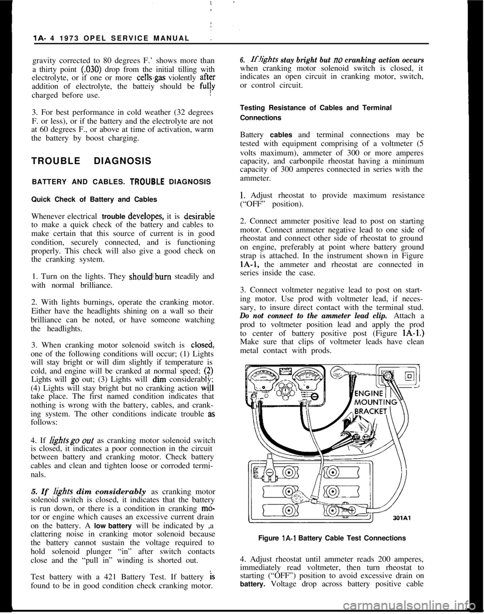
strap is attached. In the instrument shown in FigurelA-1, the ammeter and rheostat are connected in
series inside the case.
3. Connect voltmeter negative lead to post on start-
ing motor. Use prod with voltmeter lead, if neces-
sary, to insure direct contact with the terminal stud.
Do not connect to the ammeter lead clip.Attach a
prod to voltmeter position lead and apply the prod
to center of battery positive post (Figure lA-1.)
Make sure that clips of voltmeter leads have clean
metal contact with prods.
Figure l A-l Battery Cable Test Connections
4. Adjust rheostat until ammeter reads 200 amperes,
immediately read voltmeter, then turn rheostat to
starting (“OFF”) position to avoid excessive drain on
battery. Voltage drop across battery positive cable
Page 33 of 625
19- 12 1973 OPEL SERVICE MANUAL :ConditionPosiible CauseCorrection4. Voltage drop.1. Check wiring and wiring
connections.
5. Overrun&g clutch slips.1. Replace overrunning clutch.
The cranking motor keeps
on rotating after ignition
switch is off.1. Ignition
{witch does not
cut off or solenoid switch
sticks.
1, Immediately disconnect cranking
motor cable from battery. Inspect
and/or replace or repair ignition and
solenoid switches as required.
The drive pinion does notdemesh after engine has
been cranked.1. Drive pinion or ring gear
1. Clean components as specified.
teeth clogged or flattened.Replace as required.
Return spring slack or broken.MAlNTEilANCE AND ADJUSTMENT
/
STARTING SYSTEM CHECKS
Voltage Loss ChecksWhen the starter cranks too slowly, check the bat-
tery state of charge and all electrical connections
between the battery and starter.
1. Turn on headlights and
opera’te starter. If head-
lights dim considerably when starter is engaged, the
battery may be discharged or be defective. Check the
battery.
2. If the headlights stay bright but the starter d&s
not turn over, the starter cables may be faulty or the
starter defective.
(a) Test battery voltage while cranking engine
1(9volts minimum).
(b) Check voltage from starter tkrminal of solenoid
to starter frame while cranking engine.
3. The difference in readings taken in Operations 2a
and 2b above represents the
volt& drop through the
cables and solenoid switch. Voltdge drop should
Gotexceed
.5 volt.
4. Locate excessive resistance as follows:
(a) Turn voltmeter to scale above 12 volts and con-
nect voltmeter leads
across connection or switch: to
be checked.
(b) With starter switch closed, turn voltmeter switch
to lowest scale and take reading as quickly as possi-
ble, then turn switch back to higher scale and stop
cranking engine.(c) Voltmeter must not read more than
.2 volt across
any
c:onnection. If voltmeter reads more than .2 volt,
the
d~efect must be corrected.
Starter Current Draw - Lock Test1. Make sure battery is fully charged and in good
condition.
2. Connect a volt ampere starter tester according to
manufacturer’s instructions.
3. Pull parking brake on securely, shift transmission
into 4th (direct) gear and actuate starter. (Starter will
not
t,urn engine because engine is locked through
transmission.)
4. While starter is actuated, read voltage and current.
Refer to Specification Chart.
(a) Voltage low
_ poor battery or a voltage loss in the
starter circuit.
(b) Current high
- short circuit in starter. Overhaul
starter.
(c) Current low
- commutator dirty, brushes worn,
solenoid switch contacts defective or open circuit in
starter. Overhaul starter.
Starter Current Draw. On Car1. Bring engine to normal operating temperature.
2. Stop engine and disconnect coil wire from dis-
tributor.
3. Ground coil wire to prevent excessive coil voltage
build up.
Page 66 of 625

LIGHTING SYSTEMSlF-45LIGHTING SYSTEMS
CONTENTS
Subject
DESCRIPTION AND OPERATION:
LightingSystems................................................................
DIAGNOSIS:MAINTENANCT AND ADJUSTMENTS:
Headlamp Aiming..............................................................
MAJOR REPAIR:
Opel 1900
- Manta
HeadlightSwitch............................................................
Fog Lamp or Heated Rear Window Switch
..........
SealBeam........................................................................
Tail Lamps........................................................................
LicensePlateLamp........................................................
FrontSideMarker..........................................................
Rear Side Marker..........................................................
Courtesy Light................................................................
DoorJamSwitch............................................................
GT
Front Turn Signal..........................................................
SealBeam........................................................................
Tail Lamps........................................................................
Side Marker......................................................................
LicensePlateLamp........................................................
Backup Lamp
..................................................................
InteriorLight....................................................................
Headlamp Switch..........................................................
DoorJamSwitch............................................................
SPECIFICATIONS:
Page No.
1 F-45
1 F-46
1 F-46
1 F-47
1 F-47
1 F-40
1 F-49
1 F-49
1 F-50
1 F-50
1 F-50lF-51lF-51lF-51
1 F-52
1 F-52
1 F-53
1 F-53
1 F-53
1 F-53
DESCRIPTION AND OPERATION
DESCRIPTION OF LIGHTING SYSTEMThe
three-baition light switch on Opel 1900 and
Manta corjtrols the headlights, taillights, parking
lights, side marker lights, instrument panel lights,
and the lic&se plate light.
When the
Qght switch knob is pulled out to the first
stop, the .pxking lights, side marker lights, the Ii-
cerise plate light, and the instrument panel lights will
light.
Pulling the knob out all the way turns the headlights
on.The instrument panel lights come on when the head-
light switch is pulled out to the first stop or pulled
out ‘all the way. The instrument panel lights are
turned off by turning the switch knob counterclock-
wise past the first detent.
Page 67 of 625
1F. 46 1973 OPEL SERVICE MANUAL
’
/
Headlight High-Low Beam Control and Passing:
SignalI
When the headlights have been switched on, high
and low beam selection is made by raising the direc-
tional signal lever toward steering wheel. Each
ti&the lever is raised, beam position, will change.
When the headlights are not on, a flashing headlight
signal may be given by raising and lotiering the di-
rectional signal lever. With the headlights on and
inlow beam position, raising and lowering the direc-
tional signal lever will also cause the headlights to
flash.
Fog Light SwitchAll Rallye models are equipped with two white f?g
lights mounted below the front bumper.
The fog light toggle switch is located on the
insty-ment cluster to the left of the temperature and
fuelgauge cluster.
/
The fog lights can be turned off at any time by the
toggle switch, but can only be tyrned on when: :
1. The ignition switch on or the
?gine running.!
2. The fog light toggle switch lower half is pushed
in.3. The parking lights and/or low beam headlights
are
OKThe fog lights are automatically turned off if the
ignition switch is on and the headlights are switched
to high beam position.
Courtesy LightThe courtesy light illuminates the interior of the Car
when any door is opened. The courtesy light can also
be turned on with all doors closed by tilting the l&s.
GT Headlamp MechanismThe concealed headlamps are moved mechanically.
Pushing actuating lever on left side of console opens
headlamps and pulling lever closes headlamps. Two
(2) meshing gear segments convert the movement, of
the lever to a rotation of 180 degrees. The pivots of
the headlamps lie below the centerline so that with
headlamps in closed position, the headlamp housing
is flush with front sheet metal. Refer to Group 110,
Section “F”, for service procedures on the GT head-
lamp mechanism.
A white indicator lamp in the instrument panel lights
if the headlamps are not completely opened lorclosed The switches of the headlamp electrical sys-
tem are located behind the left headlamp operating,
mechanism.
MAINTENANCE AND ADJUSTMENTSHEADLAMP AIMING
The headlamps must be properly aimed in order to
obtain maximum road illumination and safety that
has been built into the headlighting equipment. With
the Guide T-3 type sealed beam units, proper aiming
is even more important because the increased range
and power of this lamp make even slight variations
from recommended aiming hazardous to approach-
ing motorists. The headlamps must be checked for
proper aim whenever a sealed beam unit is replaced
and after an adjustment or repairs of the front end
sheet metal assembly.
Regardless of method used for checking headlamp
aim, car must be at normal weight, that is, with gas,
oil, water, and spare tire. Tires must be uniformly
inflated to specified pressure. If car will regularly
carry an unusual load in rear compartment, or a
trailer, these loads should be on car when headlamps
are checked. Some States have special requirements
for headlamp aiming adjustment, and these require-
ments should be known and observed.
Horizontal and vertical aiming of each seal beam
unit is provided by two adjusting screws which move
the mounting ring in the body against the tension of
the coil spring. There is no adjustment for focus,
since the sealed beam unit is set for proper focus
during manufacturing assembly.
MAJOR REPAIRHEADLIGHT SWITCH
- OPEL 1900. MANTA
Removal1. Remove instrument cluster cover panel. See Sec-
tion H.
2. Compress retaining springs and pull switch out.
See Figure 1 F-
1.3. Pull multiple socket off switch.
Installation
1: Plug multiple socket in switch and push switch in
panel until clips lock in place.
2. Replace instrument cover and secure with two (2)
screws.
Page 75 of 625

lG- 54 1973 OPEL SERVICE’ MANtiAL/SIGNAL SYSTEMSCdNTENTS
9Subject
DESCRIPTION AND OPERAT!ON:
Directional Signal Lever
. . . . . . . . . . . . . . . . . . . . . . . . . . . . . . . . . . . . . . . . . . . . . . . . . .
Horn. . . . . . . . . . . . . . . . . . . . . . . . . . . . . . . . . . . . . . . . . . . . . . . . . . . . . . . . . . . . . . . . . . . . . . . . . . . . . . . . . . . . . . . .HazardWarning
Flasher. . . . . . . . . . . . . . . . . . . . . . . . . . . . . . . . . . . . . . . . . . . . . . . .BrakeSystemWarningLight
. . . . . . . . . . . . . . . . . . . . . . . . . . . . . . . . . . . . . . . .DIAGNOSIS:
SignalSystem,.......................
i . . . . . . . . . . . . . . . . . . . . . . . . . . . . . . . . . . . . . . . . . . . . .MAINTENANCE AND ADJUS,TMENTS:
MAJOR REPAIR:
Directional Signal Switch
:. . . . . . . . . . . . . . . . . . . . . . . . . . . . . . . . . . . . . . . . . . . . .
HornRemoval. . . . . . . . . . . . . . . . . . . . . . . . . . . . . . . . . . . . . . . . . . . . . . . . . . . . . . . . . . . . . . . . . . . . . .Removing Horn Contact
. . . . :.............................................
SPECIFICATIONS:
FuseChart. . . . . . I . . . . . . . . . . . . . . . . . . . . . . . . . . . . . . . . . . . . . . . . . . . . . . . . . . . . . . . . . . . . . . . . . . . . .Page No.
1 G-54
1 G-54
1 G-55
lG-55 _1 G-55
1 G-55
16-551 G-55
1 G-56
DESCRIPTION AND OPERATION
DIRECTIONAL SIGNAL LEVERThe direction signal switch lever is a multi- purpose
lever controlling direction signals, passing signal,
and high and low beams. See Figure
lG-1.301Gl
Figure lG-1 Directional Signal Position for Headlamp
OperationThe direction signal lever is provided with a
two-step mechanism for operation of headlight high and
low beams, and passing signal (not in New Jersey).
With headlights off, moving the lever repeatedly to-
wards steering wheel flashes headlights as a passing
signal. With headlights on, moving the lever repeat-
edly towards steering wheel up to first stop also
flashes passing signal regardless whether or not the
direcl:ion signals are switched on. When the lever is
moved up to the second stop, the headlights are
changed from high to low beam
dr vice versa. On all
Rallye cars, when switching from low to high beam
position, with the fog lamp instrument panel switch
“ON” and ignition switch in “RUN” position, the
fog lights are automatically
switChed off. Direction
signals work in the normal manner; pushing the lever
up for right turn signal and pulling the lever down
for left turn signal.
The horn button is located in the center part of the
steering wheel. The horn is actuated by pushing
down on the ends of both spokes on Opel 1900 andManta’s or on the center horn button on the Rallye.
The button is provided with a spring-loaded plunger.See Figure
lG-2.
Page 78 of 625

,I
IINSTRUMENT PANEL
lH- 57
/
/SubjectPage No. INSTRUMENT PANEL
CONTENTS
DESCRIPTION AND OPERATION:
Instrument Panel
- Opel 1900 - Manta. . . . . . . . . . . . . . . . . . . . . .Instrument
Panel-GT. . . . . . . . . . . . . . . . . . . . . . . . . . . . . . . . . . . . . . . . . . . . . . . . . . . . . .DIAGNOSIS:
MAINTENANCE AND ADJUSTMENTS:
MAJOR REPAIR:
Instrument Cluster Housing
- Opel 1900 - Manta . .
Windshield Wiper Switch
. , . . . . . . . . . . . . . . . . . . . . . . . . . . . . . . . . . . . . . . . . . . . .InstrumentCluster
Bulbs. . . . . . . . . . . . . . . . . . . . . . . . . . . . . . . . . . . . . . . . . . . . . . . .InstrumentCluster
Housing-GT. . . . . . . . . . . . . . . . . . . . . . . . . . . . . . . . . .Combined Switch Assemblies
. . . . . , . . . . . . . . . . . . . . . . . . . . . . . . . . . . . . . .CigarLighter
. . . . . . . . . . . . . . . . . . . . . . . . . . . . . . . . . . . . . . . , . . . . . . . . . . . . . . . . . . . . . . . . . . . . . . . .SPECIFICATIONS: (Not Applicable)
I H-57
1H-58
1H-59
1H-61
lH-61
1H-61
1H-63
1H-64
DESCF(lPTlON AND OPERATION2. The fog light toggle switch lower half is pushed in.INSTRUFENT PANEL (OPEL 1900. MANTA)
Headligl$ Switch
3. The parking lights and/or low beam headlights are
on.The thr& position light switch controls the head-
lights, @lights, parking lights, side marker lights,
license
plate light and instrument panel lights and is
located
4t the lower left on the instrument panel.
With thk switch knob pulled outward to the first
stop,
thi parking lights, side marker lights, license
plate
ligiit and instrument panel lights will light. Theinstrumdnt panel lights can be turned off by turning
the
lightSwitch knob counterclockwise past the first
detent. IThe fog lights are automatically turned off if the
ignition switch is on and the headlights are on high
beam.
Windshield Wiper Switch
The windshield wiper switch is located on the instru-ment panel to the right of the headlight switch.
By pull&g the lightswitch knob out all the way, the
headlights will also be turned on.
IBy pushing the lower half of this switch in to the first
stop, the wipers will operate at slow speed. By push-ing in to the second stop, the wipers will operate at
fast speed.
Fog
Ligh) Switch (Rallye)The fog
iight toggle switch is located in the instru-
ment cluster to the left of the temperature and fuel
gauge
cl+ster. The fog lights can be turned off at any
time by
t,he toggle switch, but can only be turned on
when: ,
Electrically Heated Rear Window Switch (If
Equipped)The heated rear
wind&v switch is located in the
instrument panel to the right of the clock opening.
1. The ignition switch is on or the engine running.
ITo operate (only possible with the engine running),
push in on the lower half of the switch. When the
rear window is being heated, the switch will
belighted.
Page 79 of 625
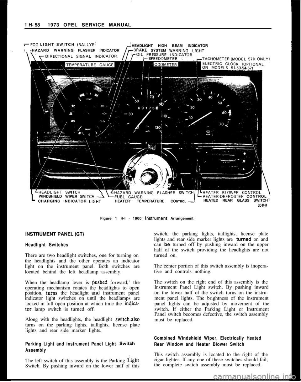
1 H- 581973 OPEL SERVICE MANUAL
/-FOG LIGHT SWITCH IRALLYEi
\HEADLIGHT HIGH BEAM INDICATOR
-HAZARD WARNINGFLASHERINDICATORSYSTEM WARN,NGLlGHT
LWINDSHIELD WIPER SWlTCH -1 LFUEL&,UGELHEATER-DEFROSTER CONTROL
CHARGING INDICATOR LlGHTHEATER’ TEMPERATURE CONTROLHEATED REAR GLASS SWITCH1
301H1Figure 1 H-l
- 1900 lnstrumellt Arrangement
INSTRUMENT PANEL
(GT)I
Headlight SwitchesThere are two headlight switches, one for turning on
the headlights and the other operates an indicator
light on the instrument panel. Both switches are
located behind the left headlamp assembly.
When the headlamp lever is @shed forward,’ the
operating mechanism rotates the headlights to open
position, tuins the headlight and instrument panel
indicator light switches on until the headlamps are
locked in full open position at which time the indica-
tar lamp switch is turned off.
Along with the headlights, the headlight switch,also
turns on the parking lights, taillights, license plate
lights and rear side marker lights.
Parking Light and instrument Panel Light SwitCh
AssemblyThe left switch of this assembly is the Parking Light
Switch. By pushing inward on the lower half of thisswitch, the parking lights, taillights, license plate
lights and rear side marker lights are turned on and
can be turned off by pushing inward on the upper
half of the switch providing the headlights are not
turned on.
The center portion of this switch assembly is inopera-
tive and controls nothing.
The switch on the right end of this assembly is the
Instrument Panel Light switch. By pushing inward
on the lower half of the switch turns on the instru-
ment panel lights. The brightness of the instrument
panel lights can be adjusted by movement of the
switch. If either the Parking Light or Instrument
Panel switch becomes defective, the switch assembly
must be replaced.
Combined Windshield Wiper, Electrically Heated
Rear Window and Heater Blower SwitchThis switch assembly is located to the right of the
cigar lighter. If any one of these switches should fail,
the complete switch assembly must be replaced.
Page 202 of 625

OPEL 1900 AND MANTA STEERING COLUMN ASSEMBLY 3E.35
II
OPEL 1900 AND MANTA STEERING COLUMN
ASSEMBLY
CONTENTS
SubjectPage No.
DESCRIPTION AND OPERATION:
Description and Operation of Directional Signal
Lever. . . . . . . . . . . . . . . . . . . . . . . . . . . . . . . . . . . . . . . . . . . . . . . . . . . . . . . . . . . . . . . . . . . . . . . . . . . . . . . . . .Description
andOperationofHorn. . . . . . . . . . . . . . . . . . . . . . . . . . . . . .Description of Steering Column Assembly
. . . . . . . . . . . . . .DIAGNOSIS: (Not Applicable)
MAINTENANCE AND ADJUSTMENTS: (Not
Applicable)
MAJOR REPAIR:
3E-353E-363E-36
Removal and Installation of Steering Column
Assembly
. . . . . . . . . . . . . . . . . . . . . . . . . . . . . . . . . . . . . . . . . . . . . . . . . . . . . . . . . . . . . . . . . . . . . . . . . .
RemovalandInstallationofSteeringWheel. . . . . . . . . . . .Disassembly and Reassembly of Direction Signal
Switch
. . . . . . . . . . . . . . . . . . . . . . . . . . . . . . . . . . . . . . . . . . . . . . . . . . . . . . . . . . . . . . . . . . . . . . . . . . . . . . . .Disassembly and Reassembly of Steering and
Ignition Lock Cylinder, and Electrical Switch
from Mast Jacket Assembly
. . . . . . . . . . . . . . . . . . . . . . . . . . . . . . . . . . . . .SPECIFICATIONS:
Steering
ColumnSpecifications. . . . . . . . . . . . . . . . . . . . . . . . . . . . . . . . . . . .3E-363E-383E-393E-403E-41
DESCRIPTION AND OPERATIONDESCRIPTION AND OPERATION OF
DIRECTIONAL SIGNAL LEVERhigh to low beam or vice versa. On all
19M) Rallye
cars, when switching from low to high beam posi-
tion, with the fog lamp instrument panel switch ON
The direction signal switch lever is a multi- purpose
lever controlling direction signals, passing signal and
headlight high and low beams. See Figure
3E-2.The dire&M signal lever is provided with a two-
step mechanism for operation of headlight high and
low beams, and passing signal (not in N.J.). With
headlights off, moving the lever repeatedly towards
steering wheel flashes headlights as a passing signal.
With headlights on, moving the lever repeatedly to-
wards steering wheel up to first stop also flashes
passing signal regardless whether or not the direction
signals are switched on. When the lever is moved up
to the second stop, the headlights are changed from
SE.2Figure
3E-2 Directional Signal Lever Position for
Headlamp Operation