dead battery OPEL GT-R 1973 Service Manual
[x] Cancel search | Manufacturer: OPEL, Model Year: 1973, Model line: GT-R, Model: OPEL GT-R 1973Pages: 625, PDF Size: 17.22 MB
Page 30 of 625

BATTERY AND CABLES - ALL MODELSlA- 9
plus 61 terminal of the voltage regulator and protects
the circuit to the generator telltale light.
BATTERY RECHARGING
There are two separate methods of recharging batter-
ies which giffer basically in the rate of charge. In the
slow-charge method, the battery is supplied a rela-
tively small amount of current for an extended
period of time. In the quick-charge method, the bat-
tery is supplied with a high current for a short period
of time.
Slow-Charging
Slow charking is the best and only method of com-
pletely ch+rging a battery. The slow-charge method,
properly applied, may be safely used under all possi-
ble conditions of the battery, provided electrolyte is at proper
wl in all cells. The battery may be fully
charged by this method, unless the battery is not
capable of taking a full charge. The normal slow
charging rate for the
12.volt battery is 5 amperes.
Full ch&e of battery is indicated when all cell spe-
cific gravities do not increase when checked at three
intervals
of one hour and all cells are gassing freely.
Due to the low rate during slow charging, plenty of
time must ,be allowed. Charge periods of 24 hours or
more are often required.
Quick-Charging
Since time!is often of most importance to the battery
owner, quick-charging must sometimes be used to
partially charge the battery so that the engine will
start and the owner can be on his way.
Charge at:50 amperes for 20 minutes (50 times 20
equals
100Q ampere minutes). If charger will not give
this rate, charge for an equal number of ampere mi-
nutes at the best rate available. Too high a current
during quick-charging will damage battery plates.
A battery cannot be brought up to a fully charged
condition
by the quick-charge method. The battery
can be substantially recharged or boosted, but in
order to bring the battery to a fully charged condi-
tion, the charging cycle must be finished by charging
at a low
oi normal rate. Some quick-chargers have
a
provisioA for finishing the charging cycle at a low
rate so
tha’t the battery can be brought up to a fully
charged condition.
Used
with:care, and employing all safeguards prov-
ided by the manufacturer, a quick-charger will not
damage a battery
which is in good condition.
BATTERY REMOVAL AND INSTALLATION
Removal
1. Disconnect battery cables (remove negative cable
first to prevent possible shorting).
2. Remove battery hold down
l&acket.
3. Remove battery.
Installation
‘1. Place battery back in hold down position.
2. Tighten hold down bracket bolts.
3. Connect battery cables (connect positive cable first
to prevent possible shorting).
FUSIBLE LINK REMOVAL AND INSTALLATION
Replace a burned out fusible link as follows:
1. Disconnect battery.
2. Disconnect connector eye on end of fusible link.
3. Cut off other end of burned out link, along with
solder joint.
4. Strip insulation from end of new fusible link and
from end of wiring harness so that each will slide into
soldering sleeve.
5. Crimp new link in soldering sleeve and solder
carefully.
6. Cover new connection tightly with electrical tape.
I. Install new link connector eye on other end of
fusible link.
A burned out fusible link connected to the starter
solenoid would be indicated by:
1. All electrical accessories dead.
2. Starter dead - will not even click. Even with a
nearly dead battery, the starter solenoid will
gener-
ally engage; therefore, no click means no solenoid
action, possibly due to a burned out fusible link.
SPECIFICATIONS
BATTERY SPECIFICATIONS
Delco-General 12 volt-44 amp hour storage battery
is installed as original equipment. Replace with a
Delco Energizer
Y55.
Page 40 of 625

IIIGNITION SYSTEMlC- 19
11. (Startx position.) The ignition key must be
released as soon as engine starts. The switch then
returns aujomatically to the on position.
IGNITION
GOILThe ignition coil consists of a laminated non- mag-
netic iron
(core enclosed by two coils; the primary
winding and the secondary winding.
The prim+y circuit consists of the power source
(battery), the ignition switch, the ignition coil pri-
mary winding, the distributor breaker points with
ignition condenser connected in parallel, and all con-
necting
lo& tension wiring.
The secondary circuit consists of the ignition coil
secondary ‘winding, the spark plugs, all connecting
high tens@ wiring, the distributor cap and the
ro-tor.
When the’ ignition switch is turned on and the
breaker pdints are closed, current flows through the
ignition
c&l primary winding and produces a mag-
netic field wound the coil windings.
When the breaker points are separated by the revolv-
ing distributor cam, the magnetic field collapses and
induces a high voltage surge in the secondary wind-
ing,
produ;cing a spark between the spark plug elec-
trodes. ,
The ignitidn condenser which is connected in paral-
lel with the breaker points, prevents arcing between
the
separa’ted breaker contacts, and current flow
after~ the breaker points have been separated, thus
causing a kery rapid collapse of the magnetic field
around th$ Ignition coil.
/
IGNITION ‘DISTRIBUTORThe ignitidn distributor breaks the primary current,distributeslthe high voltage surges induced in the coil
secondary winding to the spark plugs according to
the engin< tiring order and sets ignition timing in
relation to. engine RPM and load.
The housi+g of the distributor contains the centrifu-
gal advance mechanism and the movable breaker
plate with’s breaker lever and contact support. The
vacuum advance mechanism is attached to the
breaker plate and mounted on the outside of the
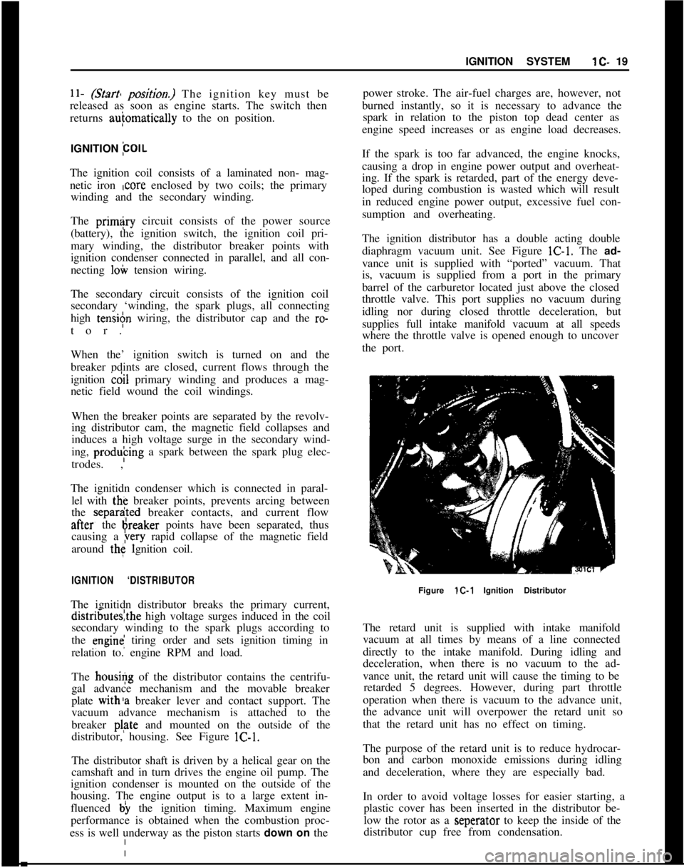
distributor, housing. See Figure lC-1.
The distributor shaft is driven by a helical gear on the
camshaft and in turn drives the engine oil pump. The
ignition condenser is mounted on the outside of the
housing. The engine output is to a large extent in-
fluenced b) the ignition timing. Maximum engine
performance is obtained when the combustion proc-
ess is well underway as the piston starts down on thepower stroke. The air-fuel charges are, however, not
burned instantly, so it is necessary to advance the
spark in relation to the piston top dead center as
engine speed increases or as engine load decreases.
If the spark is too far advanced, the engine knocks,
causing a drop in engine power output and overheat-
ing. If the spark is retarded, part of the energy deve-
loped during combustion is wasted which will result
in reduced engine power output, excessive fuel con-
sumption and overheating.
The ignition distributor has a double acting double
diaphragm vacuum unit. See Figure lC-1. The ad-
vance unit is supplied with “ported” vacuum. That
is, vacuum is supplied from a port in the primary
barrel of the carburetor located just above the closed
throttle valve. This port supplies no vacuum during
idling nor during closed throttle deceleration, but
supplies full intake manifold vacuum at all speeds
where the throttle valve is opened enough to uncover
the port.
Figure lC-1 Ignition Distributor
The retard unit is supplied with intake manifold
vacuum at all times by means of a line connected
directly to the intake manifold. During idling and
deceleration, when there is no vacuum to the ad-
vance unit, the retard unit will cause the timing to be
retarded 5 degrees. However, during part throttle
operation when there is vacuum to the advance unit,
the advance unit will overpower the retard unit so
that the retard unit has no effect on timing.
The purpose of the retard unit is to reduce hydrocar-
bon and carbon monoxide emissions during idling
and deceleration, where they are especially bad.
In order to avoid voltage losses for easier starting, a
plastic cover has been inserted in the distributor be-
low the rotor as a seperator to keep the inside of the
distributor cup free from condensation.
Page 332 of 625

FUEL SYSTEM6C- 41
covered with sound deadening compound. See Fig-
ure
6C-10.7. Remove fuel tank vent hose and tiller hose. See
Figure 6C- 11.
8. Remove fuel tank attaching bolts and gauge wire
and remove tank.
Installation
1. Install tank and tighten attaching bolts.
2. Replace gauge wire. Install vent hose, making cer-
tain it is not kinked and seal vent hose hole in floor.
3. Install spare tire support attaching brackets, sup-
port panel, hold-down, and brackets.
4. Install spare tire and jack.
5. Install fuel line and rubber cap.
6. Connect battery.FUEL LINES. FUEL GAUGE TANK UNITS
All fuel lines are plastic and have an outside diameter
of
,240 inches. Unlike metal lines, plastic lines are
not flared.
When replacing a plastic line, place the line in hot
water to make it flexible. Using the old line as a
pattern, form the new line. Let the line cool com-
pletely, then route it in the same location as the old
line. To prevent chafing against the underbody, nine
(9) rubber grommets are placed at points on the line
between the fuel tank and the fuel pump. When re-
placing fuel gauge tank units, coat gasket on both
sides and first threads of attaching screws with seal-
ing compound.
CLEANING FUEL TANK
1. Remove fuel tank.
2. Empty fuel tank through filler neck.
3. Remove fuel gauge tank unit, together with suc-
tion tube and screen. Clean screen and blow out from
cover side. Flush fuel tank.
SPECIFICATIONSFuel Tank Capacity (Gallons)
Opel 1900 and Manta
....................................................................................................11.9GT
....................................................................................................................................13.2FuelGaugeType
........................................................................................................Electrical
Fuel Pump Type
......................................................................................................Mechanical
Fuel Pump Drive
..................................................................................Eccentric on Camshaft
Fuel Pump Pressure at 1950 (RPM)................................................................3.1 to 3.7 P.S.I.FuelFilter
............................................................................................................In-LineFilter