windshield wipers OPEL GT-R 1973 Service Manual
[x] Cancel search | Manufacturer: OPEL, Model Year: 1973, Model line: GT-R, Model: OPEL GT-R 1973Pages: 625, PDF Size: 17.22 MB
Page 18 of 625

LUBRICATION AND MAINTENANCE OC-9
4. Remove dipstick and wipe clean.
5. Reinsert dipstick untip cap seats.
6. Remove dipstick and note reading.
If fluid level is at, or below the ADD mark, add
sufficient fluid to rais the level to the FULL mark.
One pint raises the level from ADD to FULL. Do
not overfill.
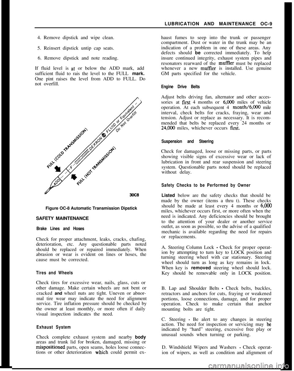
3OC8Figure OC-8 Automatic Transmission Dipstick
SAFETY MAINTENANCE
Brake Lines and HosesCheck for proper attachment, leaks, cracks, chafing,
deterioration, etc. Any questionable parts noted
should be replaced or repaired immediately. When
abrasion or wear is evident on lines or hoses, the
cause must be corrected.
Tires and WheelsCheck tires for excessive wear, nails, glass, cuts or
other damage. Make certain wheels are not bent or
cracked and wheel nuts are tight. Uneven or abnor-
mal tire wear may indicate the need for alignment
service. Tire inflation pressure should be checked by
the owner at least monthly, or more often if daily
visual inspection indicates the need.
Exhaust SystemCheck complete exhaust system and nearby body
areas and trunk lid for broken, damaged, missing orm&positioned parts, open seams, holes loose connec-
tions or other deterioration wiuch could permit ex-haust fumes to seep into the trunk or passenger
compartment. Dust or water in the trunk may be an
indication of a problem in one of these areas. Any
defects should be corrected immediately. To help
insure continued integrity, exhaust system pipes and
resonators rearward of the muftler must be replaced
whenever a new mufIler is installed. Use genuine
GM parts specified for the vehicle.
Engine Drive BeltsAdjust belts driving fan, alternator and other acces-
sories at first 4 months or
6,ooO miles of vehicle
operation. At each subsequent 4 month/6,000 mile
interval, check belts for cracks, fraying, wear and
tension. Adjust or replace as necessary. It is recom-
mended that belts be replaced every 24 months or
24,C00 miles, whichever occurs first.
Suspension and SteeringCheck for damaged, loose or missing parts, or parts
showing visible signs of excessive wear or lack of
lubrication in front and rear suspension and steering
system. Questionable parts noted should be replaced
without delay.
Safety Checks to be Performed by OwnerListed below are the safety checks that should be
made by the owner (items a thru t). These checks
should be made at least every 4 months or
6,ooOmiles, whichever occurs first, or more often when the
need is indicated. Any deficiencies should be brought
to the attention of your dealer or another service
outlet, as soon as possible, so the advise of a qualified
mechanic is available regarding the need for repairs
or replacements.
A. Steering Column Lock
_ Check for proper operat-
ion by attempting to turn key to LOCK position and
turning steering wheel with car stationary. Steering
wheel should turn as long as key remains in lock.
When key is removed steering wheel should lock.
Key should be removable only in LOCK position.
B. Lap and Shoulder Belts
- Check belts, buckles,
retractors and anchors for cuts, fraying or weakened
portions, loose connections, damage, and for proper
operation. Check to make certain that anchor
mounting bolts are tight.
C. Steering
- Be alert to any changes in steering
action. The need for inspection or servicing may
beindicated by “hard” steering, excessive free play or
unusual sounds when turning or parking.
D. Windshield Wipers and Washers
- Check operat-
ion of wipers, as well as condition and alignment of
Page 58 of 625

WINDSHIELD WIPERSlE- 37WINDSHEILD WIPERS
ALL MODELS
CONTENTS
Subject
DESCRIPTION AND OPERATION:
Windshield Wiper Motor. . . . . . . . . . . . . . . . . . . . . . . . . . . . . . . . . . . . . . . . . . . . . . .DIAGNOSIS:
Windshield Wiper
. . . . . . . . . . . . . . . . . . . , , . . . . . . . . . . . . . . . . . . . . . . . . . . . . . . . . . . . . . . . . .MAINTENANCE AND ADJUSTMENTS: (Not
Applicable)
MAJOR REPAIR:Wiper Transmission
- 1900 and Manta. . . . . . . . . . . . . . . . . . . .W/per Transmission
- GT. . . . . a.* . . . . . . . . . . . . . . . . . . . . . . . . . . . . . . . . . . . . . . . .Disassembly of Wiper Motor
. . . . . . . . . . . . . . . . . . . . . . . . . . . . . . . . . . . . . . . .Cleaning and Inspection of Parts
. . . . . . . . . . . . . . . . . . . . . . . . . . . . . . .Assembly of Wiper Motor
. . . . . . . . . . . . . . . . . . . . . . . . . . . . . . . . . . . . . . . . . . . . . .Installation
. . . . . . . . . . . . . . . . . . . . . . . . . . . . . . . . . . . . . . . . . . . . . . . . . . . . . . . . . . . . . . . . . . . . . . . . . . . .SPECIFICATIONS:
GeneralSpecifications
. . . . . . . . . . . . . . . . . . . . . . . . . . . . . . . . . . . . . . . . . . . . . . . . . . . . . .Torque Specifications
. . . . . . . a.. . . . . . . . . . . . . . . . . . . . . . . . . . . . . . . . . . . . . . . . . . . . .
DESCRIPTIOfV AND OPERATION
GENERAL;DESCRlPTlDNThe two-sbeed wiper consists of a round shaped per-
manent magnet type motor and speed reduction gear
box. IOPERATldN
=The wipei motor is controlled through a dash
mounted &itch on all cars. The Rallye and GT, in
addition tb the dash mounted switch, also have a
switch moimted in conjunction with the windshield
washer fodt pump. Depressing the washer pump will
allow the bipers to operate while the pump is de-
pressed. i
DIAGNO;SIS
PRELIMINj9RY INSPECTION
1. Make
c&in of firm wire connections at wiper
motor fuse block and wiper switch.
Page No.
1 E-37
1 E-37E-38
E-38
E-40
E-41
E-4 1E-42
1 E-43
1 E-432. Check to see that the fuse is not blown.
3. Be sure wiper motor is not loose on fire wall.
4. With the yellow wire disconnected from terminal
No. 53 on the
wi@er motor, turn the ignition switch
and wiper switch to the on position and check volt-
age available to the wiper motor. There should be 12
volts available at the durple wire with a properly
charged battery.
Checking Wiper Operation1. Turn ignition switch on and engage wiper switch
to see if wiper motor will operate.
2. If wiper action is slow or inoperative, turn swit-
ches off and detach wiper control
inn from crank
arm.3. Operate wiper manually checking for excessive
bind in linkage. Correct if necessary.
Page 60 of 625

WINDSHIELD WIPERSlE- 39
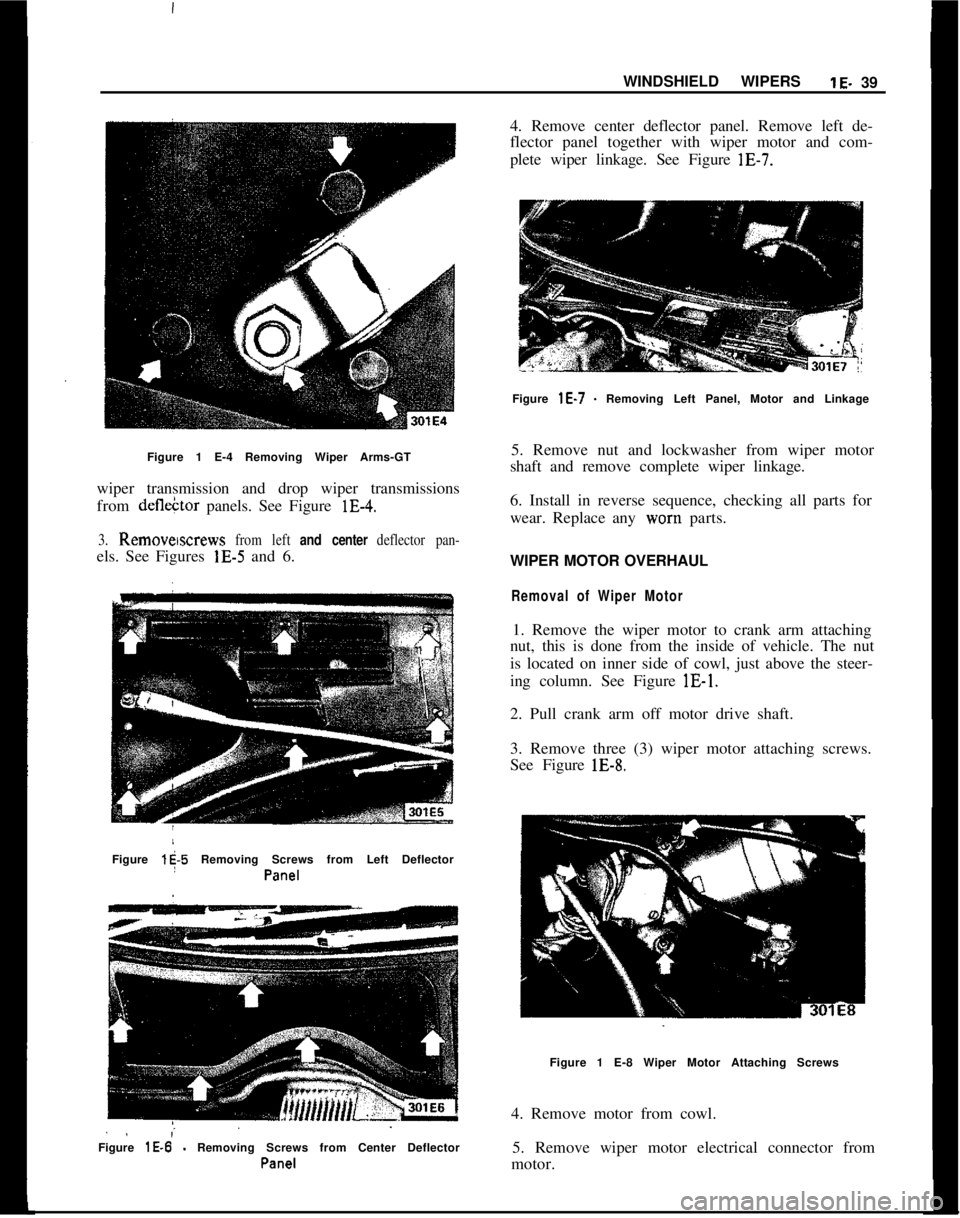
Figure 1 E-4 Removing Wiper Arms-GT
wiper transmission and drop wiper transmissions
from defleCtor panels. See Figure lE-4.3. Remowscrews from left and center deflector pan-els. See Figures lE-5 and 6.
Figure
l$-5 Removing Screws from Left Deflector
I
Pa%?1
. .;Figure
lE-6 - Removing Screws from Center Deflector
Pall-Z!14. Remove center deflector panel. Remove left de-
flector panel together with wiper motor and com-
plete wiper linkage. See Figure lE-7.
Figure
lE-7 - Removing Left Panel, Motor and Linkage
5. Remove nut and lockwasher from wiper motor
shaft and remove complete wiper linkage.
6. Install in reverse sequence, checking all parts for
wear. Replace any worn parts.
WIPER MOTOR OVERHAUL
Removal of Wiper Motor1. Remove the wiper motor to crank arm attaching
nut, this is done from the inside of vehicle. The nut
is located on inner side of cowl, just above the steer-
ing column. See Figure lE-1.
2. Pull crank arm off motor drive shaft.
3. Remove three (3) wiper motor attaching screws.
See Figure lE-8.
Figure 1 E-8 Wiper Motor Attaching Screws
4. Remove motor from cowl.
5. Remove wiper motor electrical connector from
motor.
Page 62 of 625

WINDSHIELD WIPERSlE-41
Figurk 1 E-l 3 Cut Off Positive Brush Leads
i
Figure iE-14 Remove Negative Brush Retaining
S.X?WI
Cleaning apd Inspection of PartsWith the ekception of electrical parts and bushings,
clean all components in a cleaning solvent.
1. Check irmatare windings for ground, or open
circuit. If
b ground or open circuit is evident, the
armature must be replaced. If the armature checks
out, the c
brushes should be 6.35 to 8.47 ounces. Spring pres-
sure of worn brushes should be at least 3.5 ounces.
In case of /ower spring pressure, replace springs.
3. Check blushes for wear and replace if necessary.
Minimum brush length should be
.24’inch.4. Check d$ven gear for wear and replace if neces-
sary.
Assembly
02383. I
2. Install
d&en gear into housing3. Apply a small amount of grease to ball cavity of
driven gear and insert ball. See Figure lE-15.
Figure lE-15 Insert Ball into Driven Gear
4. Install transmission housing cover. See Figure
lE-
16.2. DRIVEN GEAR
3. CONTACT SPRINGS
4. TRANSMISSION
HOUSING COVER
Figure 1 E-l 6 Install Transmission Housing
Cover5. Solder positive brush lead(s) to brush holder(s).
Hold brush lead with needle nose pliers to prevent
solder from running up wire strands. See Figure
lE-
17.6. Install negative brush
7. Apply a small amount of grease to end of armature
shaft. Lightly oil armature shaft.
8. Insert brush springs and brushes into brush hold-
ers. Slide armature into housing, taking care not to
damage brushes.
Page 64 of 625

WINDSHIELD WIPERSlE-43SPEhFlCATlONS
IGENEPAL SPECIFICATIONSiRated Voltage .
..__.,,,.,,,......................................,.,,... ~ __..__...__...._..................................... 12 VDC
,Test Voltage ___..................................................,...................,..,..................................... 13 VDC
Current Draw (Amps)
;No Load_, Low Speed
..__...__..__..,_,,..,,,.,,,,..,....................,,.................................................................. 1.5
I Hieh
SDeed .___,,...,,..,,._.._..............,...............................,,,..,,,.............................................. 2.2lLock:d
’
:Low Speed ___.,._,,,..,,,....................................,,.........,,..,,,.,,,,..................,,,........................... 16
,
High Speed . . . . . . . ..___.._........................................................................................................... 17
~Minimum Commutator Diameter __.................,,,,........................................................... .86 in.
‘Brush Spring Pressure
:New Brush
. . . . . . .._...__...................................................................................... 6.35 to 8.47 oz.Used Brush
..__,,,...,,.,,..................,...............................,,.,,,,.,,....................... 3.5 oz. minimum‘MinimumBrushLength
. . . . . . . . . . . . . . . . . . . . . . . . . . . . . . . . . . . . . . . . . . . . . . . . . . . . . . . . . . . . . . . . . . . . . . . . . . . . . . . . . . . . . . . . . . . . . . . . . .24in.The windshield wiper motor instead of field coils has a permanent magnet
(oxide magnet). This motor design is sturdier and consumes less current.TORQirE SPECIFICATIONS
‘CrankArmtoMotorDriveShaft. . . . . . . . . . . . . . . . . . . . . . . . . .70to87in.lbs.iper Motor to Cowl
,
,.,,,.,,,,..,,............,..,,.,,.........................................14 to 17 in.lbs.
Page 77 of 625

:lG- 56 1973 OPEL SERVICE MANUAL
I
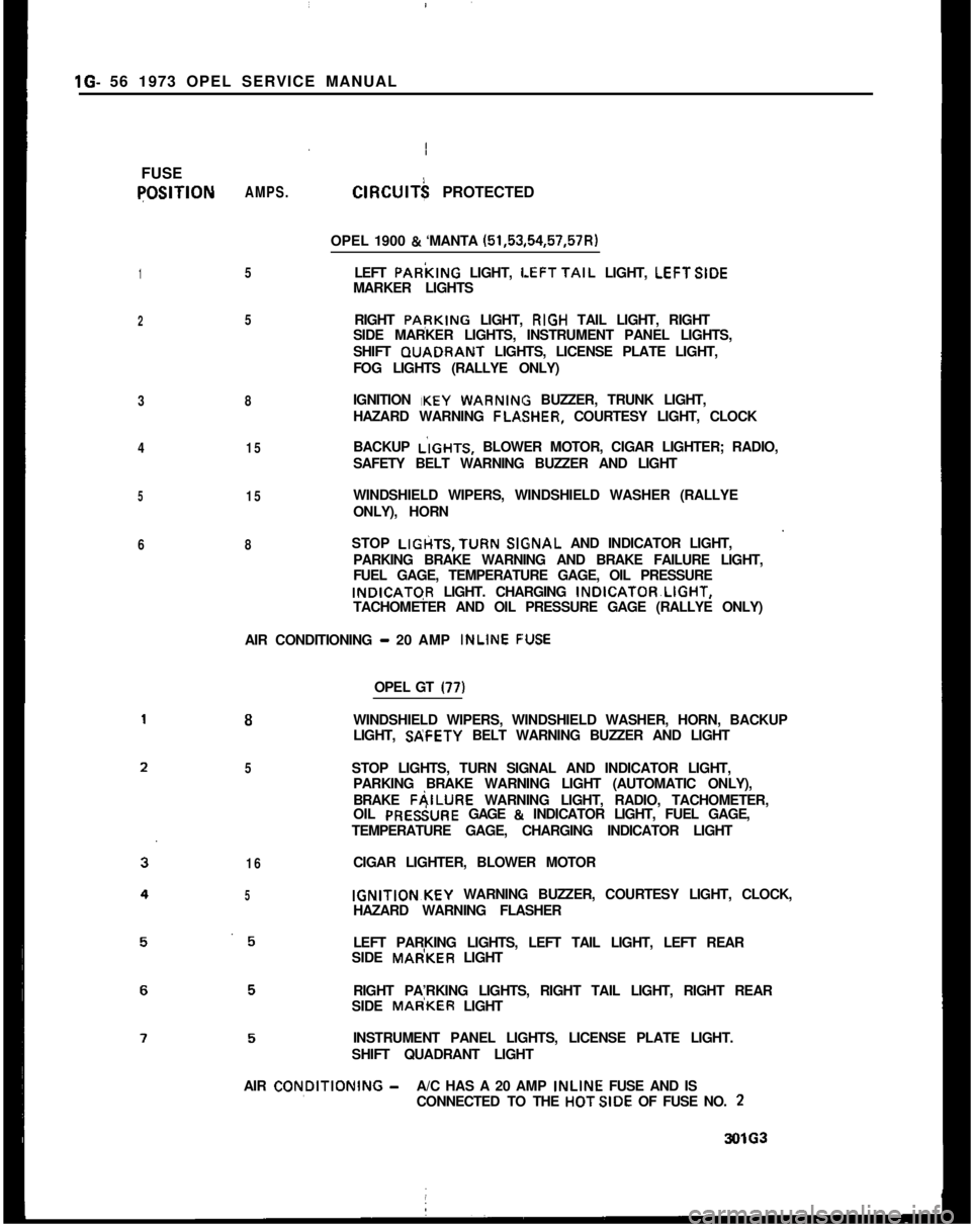
FUSEqOSlTlON
1
2
3
4
5
6AMPS.
5
5
8
15
15
8ClRClJlT$ PROTECTED
OPEL 1900
& ‘MANTA (51,53,54,57,57R)
LEFT PARkING LIGHT,
LEFTTAIL LIGHT, LEFTSIDE
MARKER LIGHTS
RIGHT PApKING LIGHT, RIGH TAIL LIGHT, RIGHT
SIDE MARKER LIGHTS, INSTRUMENT PANEL LIGHTS,
SHIFT GUADRANT LIGHTS, LICENSE PLATE LIGHT,
FOG LIGHTS (RALLYE ONLY)
IGNITION IKEY
WARNIN BUZZER, TRUNK LIGHT,
HAZARD WARNING FLA,SHER, COURTESY LIGHT, CLOCK
BACKUP L’IGHTS, BLOWER MOTOR, CIGAR LIGHTER; RADIO,
SAFETY BELT WARNING BUZZER AND LIGHT
WINDSHIELD WIPERS, WINDSHIELD WASHER (RALLYE
ONLY), HORN
STOP LIGtiTS,TURN
SlGsNAL AND INDICATOR LIGHT,
PARKING BRAKE WARNING AND BRAKE FAILURE LIGHT,
FUEL GAGE, TEMPERATURE GAGE, OIL PRESSUREINDICATGR LIGHT. CHARGING INDICATOR~LIGHT,
TACHOMETER AND OIL PRESSURE GAGE (RALLYE ONLY)
AIR CONDITIONING
- 20 AMP INLINE F:USE
8
5
16
5OPEL GT
(77)WINDSHIELD WIPERS, WINDSHIELD WASHER, HORN, BACKUP
LIGHT, SP;FETY BELT WARNING BUZZER AND LIGHT
STOP LIGHTS, TURN SIGNAL AND INDICATOR LIGHT,
PARKING BRAKE WARNING LIGHT (AUTOMATIC ONLY),
BRAKE FAILURE WARNING LIGHT, RADIO, TACHOMETER,
OIL PRESiURE GAGE
& INDICATOR LIGHT, FUEL GAGE,
TEMPERATURE GAGE, CHARGING INDICATOR LIGHT
CIGAR LIGHTER, BLOWER MOTORIGNITION~KEY WARNING BUZZER, COURTESY LIGHT, CLOCK,
HAZARD WARNING FLASHER
LEFT PARKING LIGHTS, LEFT TAIL LIGHT, LEFT REAR
SIDE MAdKER LIGHT
RIGHT PA’RKING LIGHTS, RIGHT TAIL LIGHT, RIGHT REAR
SIDE MAdKER LIGHT
INSTRUMENT PANEL LIGHTS, LICENSE PLATE LIGHT.
SHIFT QUADRANT LIGHT
AIR CON,DlTlONlNG
-A/C HAS A 20 AMP INLINE FUSE AND IS
CONNECTED TO THE HOTSIDE OF FUSE NO. 23OlG3
Page 78 of 625

,I
IINSTRUMENT PANEL
lH- 57
/
/SubjectPage No. INSTRUMENT PANEL
CONTENTS
DESCRIPTION AND OPERATION:
Instrument Panel
- Opel 1900 - Manta. . . . . . . . . . . . . . . . . . . . . .Instrument
Panel-GT. . . . . . . . . . . . . . . . . . . . . . . . . . . . . . . . . . . . . . . . . . . . . . . . . . . . . .DIAGNOSIS:
MAINTENANCE AND ADJUSTMENTS:
MAJOR REPAIR:
Instrument Cluster Housing
- Opel 1900 - Manta . .
Windshield Wiper Switch
. , . . . . . . . . . . . . . . . . . . . . . . . . . . . . . . . . . . . . . . . . . . . .InstrumentCluster
Bulbs. . . . . . . . . . . . . . . . . . . . . . . . . . . . . . . . . . . . . . . . . . . . . . . .InstrumentCluster
Housing-GT. . . . . . . . . . . . . . . . . . . . . . . . . . . . . . . . . .Combined Switch Assemblies
. . . . . , . . . . . . . . . . . . . . . . . . . . . . . . . . . . . . . .CigarLighter
. . . . . . . . . . . . . . . . . . . . . . . . . . . . . . . . . . . . . . . , . . . . . . . . . . . . . . . . . . . . . . . . . . . . . . . .SPECIFICATIONS: (Not Applicable)
I H-57
1H-58
1H-59
1H-61
lH-61
1H-61
1H-63
1H-64
DESCF(lPTlON AND OPERATION2. The fog light toggle switch lower half is pushed in.INSTRUFENT PANEL (OPEL 1900. MANTA)
Headligl$ Switch
3. The parking lights and/or low beam headlights are
on.The thr& position light switch controls the head-
lights, @lights, parking lights, side marker lights,
license
plate light and instrument panel lights and is
located
4t the lower left on the instrument panel.
With thk switch knob pulled outward to the first
stop,
thi parking lights, side marker lights, license
plate
ligiit and instrument panel lights will light. Theinstrumdnt panel lights can be turned off by turning
the
lightSwitch knob counterclockwise past the first
detent. IThe fog lights are automatically turned off if the
ignition switch is on and the headlights are on high
beam.
Windshield Wiper Switch
The windshield wiper switch is located on the instru-ment panel to the right of the headlight switch.
By pull&g the lightswitch knob out all the way, the
headlights will also be turned on.
IBy pushing the lower half of this switch in to the first
stop, the wipers will operate at slow speed. By push-ing in to the second stop, the wipers will operate at
fast speed.
Fog
Ligh) Switch (Rallye)The fog
iight toggle switch is located in the instru-
ment cluster to the left of the temperature and fuel
gauge
cl+ster. The fog lights can be turned off at any
time by
t,he toggle switch, but can only be turned on
when: ,
Electrically Heated Rear Window Switch (If
Equipped)The heated rear
wind&v switch is located in the
instrument panel to the right of the clock opening.
1. The ignition switch is on or the engine running.
ITo operate (only possible with the engine running),
push in on the lower half of the switch. When the
rear window is being heated, the switch will
belighted.