clock setting OPEL GT-R 1973 Service Manual
[x] Cancel search | Manufacturer: OPEL, Model Year: 1973, Model line: GT-R, Model: OPEL GT-R 1973Pages: 625, PDF Size: 17.22 MB
Page 27 of 625
j
/lA- 61973 OPEL SERVICE MANUAL
Do not overfill, as electrolyte may
be sprayed out by
gassing or may overtlow due to heat expansion dur:
ing charging.
If distilled water is not available, it is better to add
clean, mineral-free tap water than to allow the
elec2trolyte level to remain below the top of the plates:
In freezing weather the water should be added just
before using the car or otherwise charging the bat-
tery so that the water will be mixed with the acid
before it is allowed to stand in freezing temperatures.
If it is found necessary to add water to the
batterimore frequently than about every
1,ooO miles and the
quantity of water added per cell is’ excessive, check
setting of voltage regulator and adjust, if necessary:
Abnormal water loss is an indication that the battery
is being overcharged.
Inspect Battery, Mounting and Cables
Check outside of battery for damage or signs of se&ous abuse such as broken case or broken covers:
Check inside of battery by removing the vent caps
and inspecting for signs of abuse
stich as electrolyte
level too low to see, or bad or unusual odors. If
battery shows signs of serious damage or abuse, it
should be replaced.
Check the battery hold down bolts to make certain
that battery is securely held in place. The nut should
be drawn up to 20 lbs. in.;excessjve tightening may
distort or crack the battery case.If the top of battery is dirty or the hold down str?e
is corroded, clean thoroughly with a brush dipped
IFammonia or soda solution. Care must be used td
prevent any solution from getting into battery
cellslAfter the foaming of solution stops, flush off witli
clean water and dry thoroughly. If hold down strap
is corroded it should be painted with acid-resisting
paint after cleaning.
Check battery cables to make certain they are tight
at bracket and junction block. If a connection is
found loose it should be cleaned before being tight;ened as arcing and corrosion may have taken place
in the loose connection. Check condition of cables
and replace if badly corroded or frayed.
Special attention must be given to,the battery posi-
tive cable position to eliminate the possibility of con-
tact with the exhaust manifold on the 1.1 liter engine.
The cable clamp must be rotated clockwise as neces-
sary for the cable to run at a 45 degree angle toward
the right wheelhouse panel.
Cleaning Cable Terminals
If loose connections are found by inspection, or highresistance is found by voltage test, disconnect the
cable for thorough cleaning of terminals. When
removing a corroded cable terminal from battery
post, do not pry against battery case or hammer on
terminal to break it loose, since either practice will
result in broken cell covers. Use a screw-type termi-
nal puller if terminal cannot be loosened by hand.
Thoroughly clean all corrosion from disconnected
battery cable terminals and terminal posts, using
suitable wire brushes. If wire brushes are not availa-
ble, corroded terminals may be cleaned by brushing
with a strong soda solution, using care not to get
solution into battery cells.
If
cabbz strands are broken, corroded, or loose in
terminals, the cable should be replaced with the cor-
rect cable to insure ample capacity.
To prevent corrosion of battery terminals and con-
nections, apply a coating of petroleum jelly over the
battery post and cable terminals after cables have
been installed on terminals.
421 BATTERY TEST421 Battery Testers, manufactured and sold by a
number of companies, are the only battery testers
approved by Delco-Remy Division for testing one-
piece cover batteries. They are also used by United
Motors Service to determine whether or not a battery
is defective.
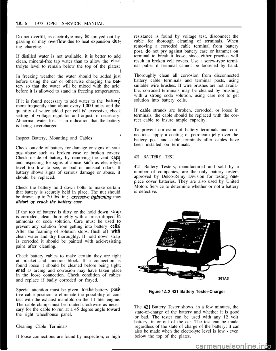
Figure lA-3 421 Battery Tester-Charger
The
42,l Battery Tester shows, in a few minutes, the
state-of-charge of the battery and whether it is good
or bad. The tester can be used with any 12 volt
battery, in or out of the car. The test can be made
regardless of the state of charge of the battery; it can
also be made when the electrolyte level is low
- even
below the top of the plates.
Page 341 of 625
6E- 501973 OPEL SERVICE MANUALMAINTENANCE AND ADJUSTMENTS
IDLE SPEED ADJUSTMENT
Note:
Idle speeds of 600 to 800 R.P.M. are normal
for engines with less than
3,ooO miles.Prior to making any adjustment to the carburetor,
the following items must be checked for proper oper-
ation and/or setting:
1. Valve Adjustment (Hydraulic lifters can be im-
properly adjusted.)
2. Dwell Angle.
3. Ignition Timing.
4. Spark Plug Gap.
5. Exhaust Gas Recirculation Valve (See “Check-
ing” under EXHAUST GAS RECIRCULATION
SYSTEM.)
After it has been ascertained that the above items are
properly adjusted and operating correctly and idle
R.P.M. is still not within specifications, proceed as
follows:
1. With air cleaner installed, run engine until normal
operating temperature is reached.
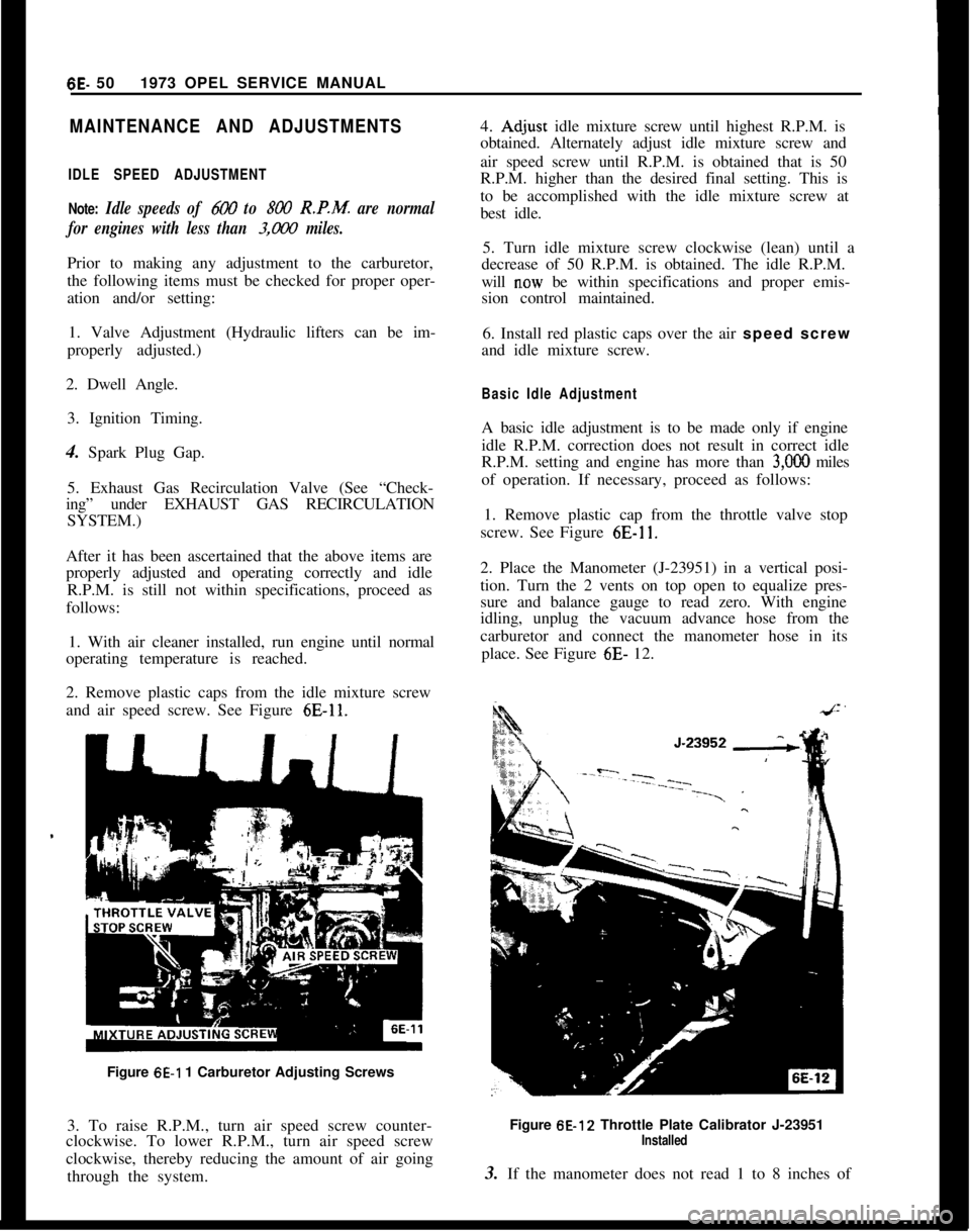
2. Remove plastic caps from the idle mixture screw
and air speed screw. See Figure
6E-11.Figure
6E-1 1 Carburetor Adjusting Screws
3. To raise R.P.M., turn air speed screw counter-
clockwise. To lower R.P.M., turn air speed screw
clockwise, thereby reducing the amount of air going
through the system.4.
Ad,just idle mixture screw until highest R.P.M. is
obtained. Alternately adjust idle mixture screw and
air speed screw until R.P.M. is obtained that is 50
R.P.M. higher than the desired final setting. This is
to be accomplished with the idle mixture screw at
best idle.
5. Turn idle mixture screw clockwise (lean) until a
decrease of 50 R.P.M. is obtained. The idle R.P.M.
will
n.ow be within specifications and proper emis-
sion control maintained.
6. Install red plastic caps over the air speed screw
and idle mixture screw.
Basic Idle AdjustmentA basic idle adjustment is to be made only if engine
idle R.P.M. correction does not result in correct idle
R.P.M. setting and engine has more than
3,OOO miles
of operation. If necessary, proceed as follows:
1. Remove plastic cap from the throttle valve stop
screw. See Figure
6E-11.2. Place the Manometer (J-23951) in a vertical posi-
tion. Turn the 2 vents on top open to equalize pres-
sure and balance gauge to read zero. With engine
idling, unplug the vacuum advance hose from the
carburetor and connect the manometer hose in its
place. See Figure 6E- 12.
Figure 6E-12 Throttle Plate Calibrator J-23951
Installed3. If the manometer does not read 1 to 8 inches of
Page 359 of 625
6G- 68 1973 OPEL SERVICE MANUAL
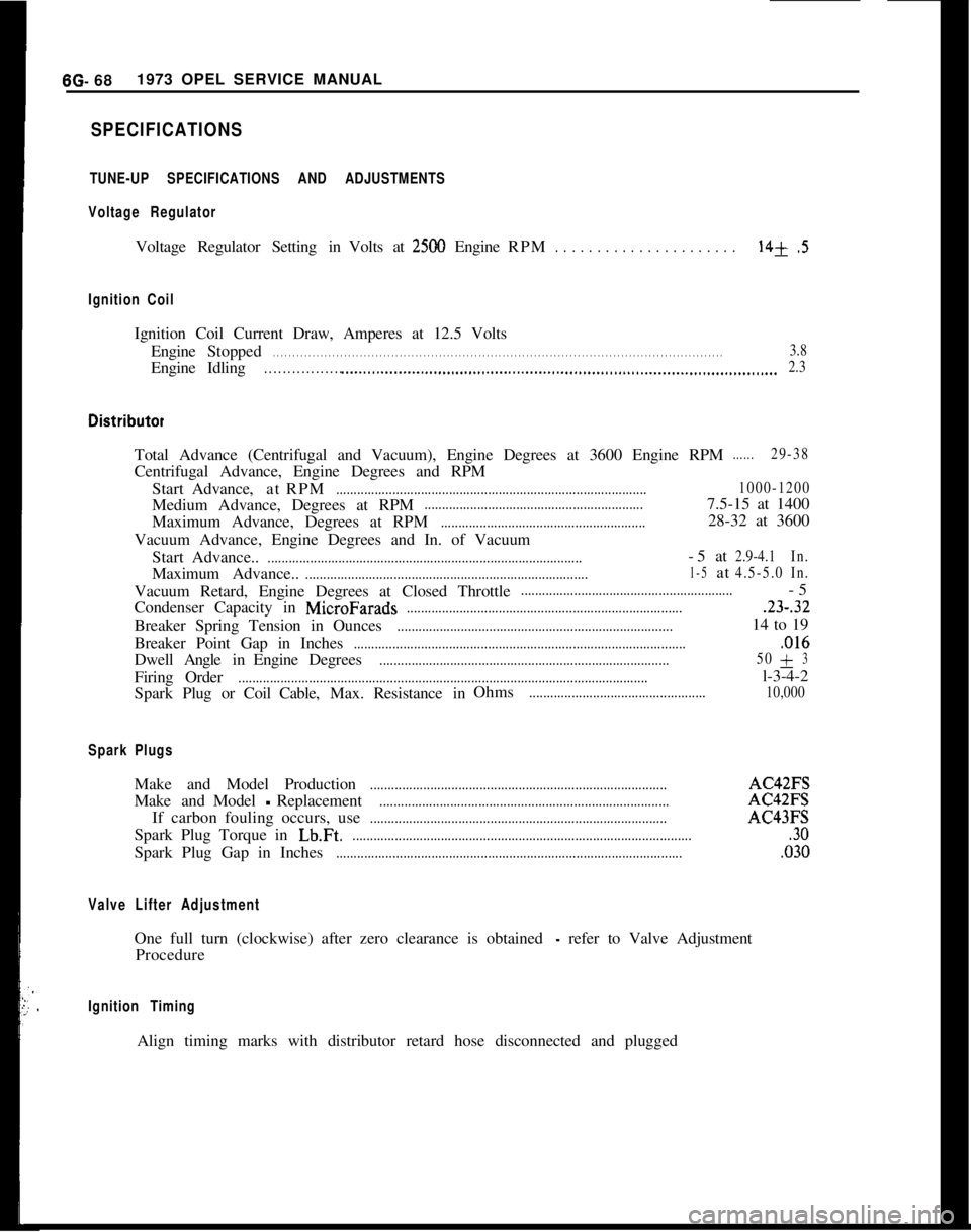
SPECIFICATIONS
TUNE-UP SPECIFICATIONS AND ADJUSTMENTS
Voltage Regulator
Voltage Regulator Setting in Volts at2500 Engine RPM. . . . . . . . . . . . . . . . . . . . . .14+.5
Ignition Coil
Ignition Coil Current Draw, Amperes at 12.5 Volts
Engine Stopped
. . . . . . . . . . . . . . . . . . . . . . . . . . . . . . . . . . . . \
. . . . . . . . . . . . . . . . . . . . . . . . . . . . . . . . . . . . \
. . . . . . . . . . . . . . . . . . . . . . . . . . . . . . . . . . . . \
. . . . . .3.8
EngineIdling. . . . . . . . . . . . . . . . . .._.....................................................................\
........................... 2.3
Total Advance (Centrifugal and Vacuum), Engine Degrees at 3600 Engine \
RPM......29-38
Centrifugal Advance, Engine Degrees and RPM
Start Advance, atRPM
........................................................................\
................ 1000-1200
Medium Advance, Degrees at RPM..............................................................7.5-15 at 1400
Maximum Advance, Degrees at RPM
..........................................................28-32 at 3600
Vacuum Advance, Engine Degrees and In. of Vacuum Start Advance..
........................................................................\
.................-5at2.9-4.1 In.
Maximum Advance..........................................................................\
........1-5at4.5-5.0In.
Vacuum Retard, Engine Degrees at Closed Throttle............................................................-5
Condenser Capacity in
MicroFarads........................................................................\
.......23-.32
Breaker Spring Tension in Ounces........................................................................\
......14 to 19
Breaker Point Gap in Inches
........................................................................\
......................,016
Dwell AngleinEngine Degrees........................................................................\
.......... 50+3
Firing
Order........................................................................\
............................................l-3-4-2
Spark Plug or Coil Cable,Max.Resistance in Ohms
..................................................
10,000
Spark Plugs
Make and Model Production........................................................................\
............AC42FS
Make andModel
-Replacement........................................................................\
..........AC42FS
If carbon fouling occurs, use
........................................................................\
............AC43FS
Spark Plug Torque in
Lb.Ft.........................................................................\
.........................30
Spark Plug Gap in Inches........................................................................\
..........................,030
Valve Lifter Adjustment
One full turn (clockwise) after zero clearance is obtained - refer to Valve Adjustment
Procedure
Ignition Timing
Align timing marks with distributor retard hose disconnected and plugged\
Page 574 of 625
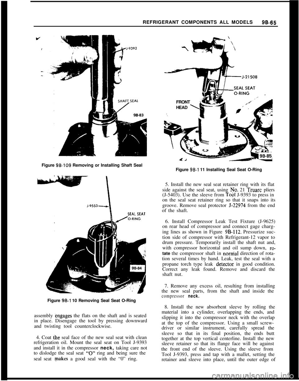
REFRIGERANT COMPONENTS ALL MODELS96-66Figure 98.109 Removing or Installing Shaft Seal
SEAL SEAT
-Figure 98-l 10 Removing Seal Seat O-Ring
assembly engages the flats on the shaft and is seated
in place. Disengage the tool by pressing downward
and twisting tool counterclockwise.
4. Coat ihe seal face of the new seal seat with clean
refrigeration oil. Mount the seal seat on Tool J-9393
and install it in the compressor neck, taking care not
to dislodge the seal seat
“0” ring and being sure the
seal seat makes a good seal with the “0” ring.FRONT
L’HEAD
\Figure 96-l 11 Installing Seal Seat O-Ring
5. Install the new seal seat retainer ring with its flat
side against the seal seat, using No. 21 Truarc pliers
(J-5403). Use the sleeve from
Top1 J-9393 to press in
on the seal seat retainer ring so that it snaps into its
groove. Remove seal protector
Jz22974 from the end
of the shaft.
6. Install Compressor Leak Test Fixture (J-9625)
on rear head of compressor and connect gage charg-
ing lines as shown in Figure
9B-112. Pressurize suc-
tion side of compressor with Refrigerant-12 vapor to
drum pressure. Temporarily install the shaft nut and,
with compressor horizontal and oil sump down,
ro-tate the compressor shaft in nornial direction of rota-
tion several times by hand. Leak, test the seal with a
propane torch type leak
detectot; in good condition.
Correct any leak found. Remove and discard the
shaft nut.
7. Remove any excess oil, resulting from installing
the new seal parts, from the shaft and inside the
compressor neck.8. Install the new absorbent sleeve by rolling the
material into a cylinder, overlapping the ends, and
slipping it into the compressor neck with the overlap
at the top of the compressor. Using a small screw-
driver or similar instrument, carefully spread the
sleeve so that in its final position, the ends butt
together at the top vertical centerline. Install the new
sleeve retainer so that its flange face will be against
the front end of the sleeve. Using the sleeve from
Tool J-9393, press and tap with a mallet, setting the
retainer and sleeve into place, until the outer edge of
Page 598 of 625
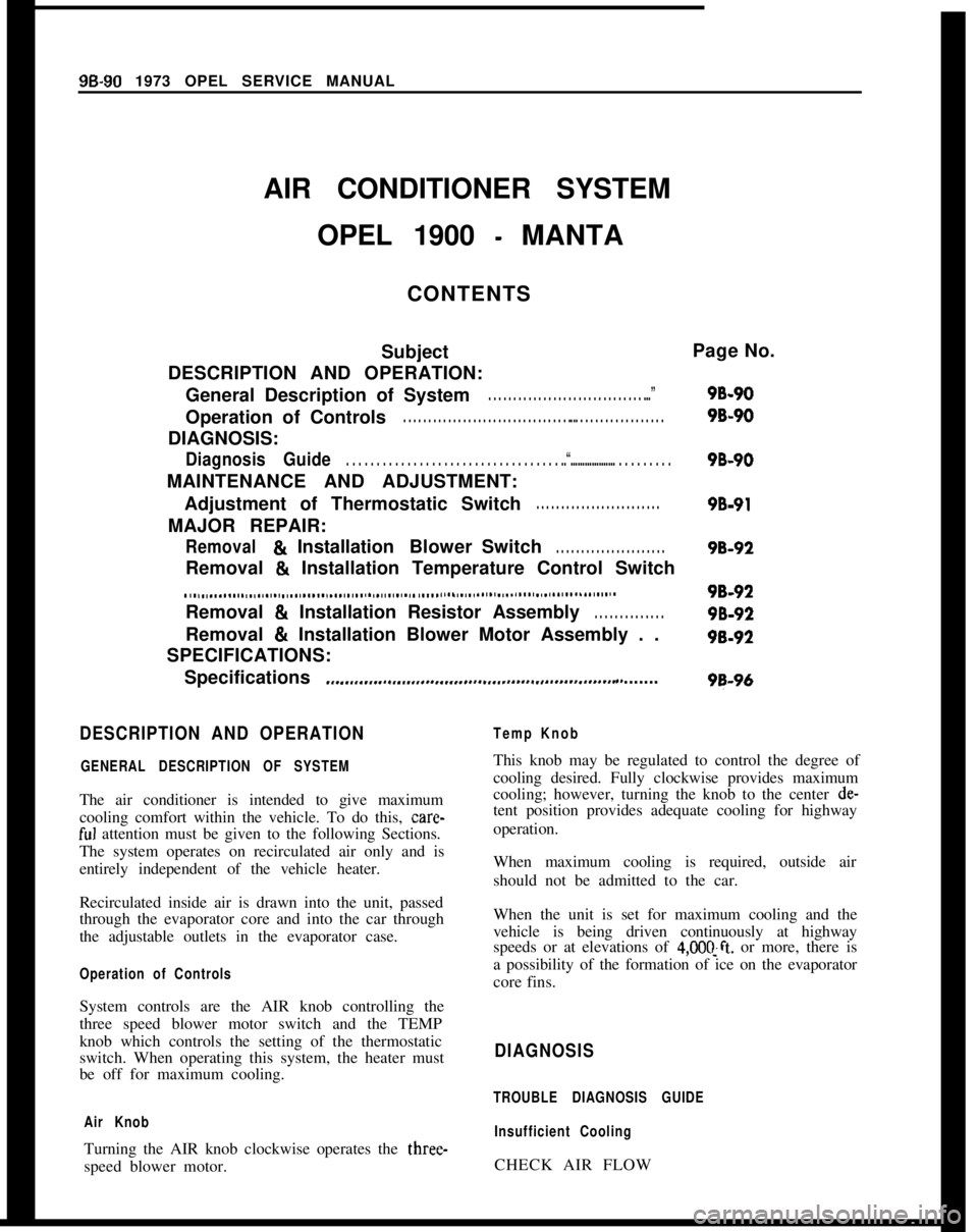
System controls are the AIR knob controlling the
three speed blower motor switch and the TEMP
knob which controls the setting of the thermostatic
switch. When operating this system, the heater must
be off for maximum cooling.DIAGNOSIS
TROUBLE DIAGNOSIS GUIDE
Air Knob
Insufficient CoolingTurning the AIR knob clockwise operates the three-
speed blower motor.CHECK AIR FLOW9B-90 1973 OPEL SERVICE MANUAL
AIR CONDITIONER SYSTEM
OPEL 1900
- MANTA
CONTENTS
Subject
DESCRIPTION AND OPERATION:
General Description of System
. . . . . . . . . . . . . . . . . . . . . . . . . . . . . . . ...”Operation of Controls
. . . . . . . . . . . . . . . . . . . . . . . . . . . . . . . . . . .. . . . . . . . . . . . . . . . . . .DIAGNOSIS:
DiagnosisGuide. . . . . . . . . . . . . . . . . . . . . . . . . . . . . . . . . . . ..“................... . . . . . . . . .MAINTENANCE AND ADJUSTMENT:
Adjustment of Thermostatic Switch
. . . . . . . . . . . . . . . . . . . . . . . . .MAJOR REPAIR:
Removal81InstallationBlowerSwitch. . . . . . . . . . . . . . . . . . . . . .Page No.
9B-90
9B-90
9B-90
9B-91
98-92Removal
& Installation Temperature Control Switch
. . . . . . . . . . . . . . . . . . . . . . . . . . . . . . . . . . . . . . . . . . . . . . . . . . . . . . . . . . . . * . . . . . . . . . . . . . . . . . . . . . . . . . . . . . . . . . . . . . . . . .Removal
& Installation Resistor Assembly. . . . . . . . . . . . . .Removal
& Installation Blower Motor Assembly . .
SPECIFICATIONS:
Specifications
.,...,,.,,..~.,.,..,,......,.,....,.,........,......,........ ,, . . . . . . .
98-92
98-92
98-92
98-96
DESCRIPTION AND OPERATION
GENERAL DESCRIPTION OF SYSTEMThe air conditioner is intended to give maximum
cooling comfort within the vehicle. To do this, care-
ful attention must be given to the following Sections.
The system operates on recirculated air only and is
entirely independent of the vehicle heater.
Temp KnobThis knob may be regulated to control the degree of
cooling desired. Fully clockwise provides maximum
cooling; however, turning the knob to the center de-
tent position provides adequate cooling for highway
operation.
When maximum cooling is required, outside air
should not be admitted to the car.
Recirculated inside air is drawn into the unit, passed
through the evaporator core and into the car through
the adjustable outlets in the evaporator case.
Operation of ControlsWhen the unit is set for maximum cooling and the
vehicle is being driven continuously at highway
speeds or at elevations of
4,OOC!ft. or more, there is
a possibility of the formation of ice on the evaporator
core fins.
Page 599 of 625
AIR CONDITIONER SYSTEM -OPEL 1900 - MANTA9B- 91FAN DOES NOT RUN Correct electrical fault.
FAN RUNS
- Check air velocity.
NOT OK Clean evaporator inlets.
Clean evaporator core.
Clean evaporator outlets.
OK Check refrigeration (refer to Refrigeration
Diagnosis Guide).
MAINTENANCE AND ADJUSTMENTS
ADJUSTMENT OF THERMOSTATIC SWITCHThe system makes use of a thermostatic switch with
a self-supporting air sensing capillary. This capillary
controls the switch by sensing the temperature of the
air leaving the evaporator fins.
Checking for Proper Operation
I. Install the gauge set and set up the vehicle as
described under FUNCTIONAL TESTING SYS-
TEM iti Refrigerant Components Section.
2. Movement of the temperature control knob
should result in a definite change in suction pressure
and cycling of the compressor clutch.
3. If compressor continues to operate regardless of
the knob adjustment, it indicates that the switch
points are fused, which will lead to evaporator
freeze- up. The switch should be replaced.
Adjusting Switch
If, after ihe foregoing checks, the switch seems to be
operating correctly, adjust for proper setting if neces-
sary, as
~follows:1. Set up car as described in FUNCTIONAL
TESTING SYSTEM in Refrigerant Components
Section.2. The suction side of the system, read on the low
pressure gauge, should pull down to the pressure
shown in the chart in SPECIFICATIONS in Refrig-
erant Components Section.
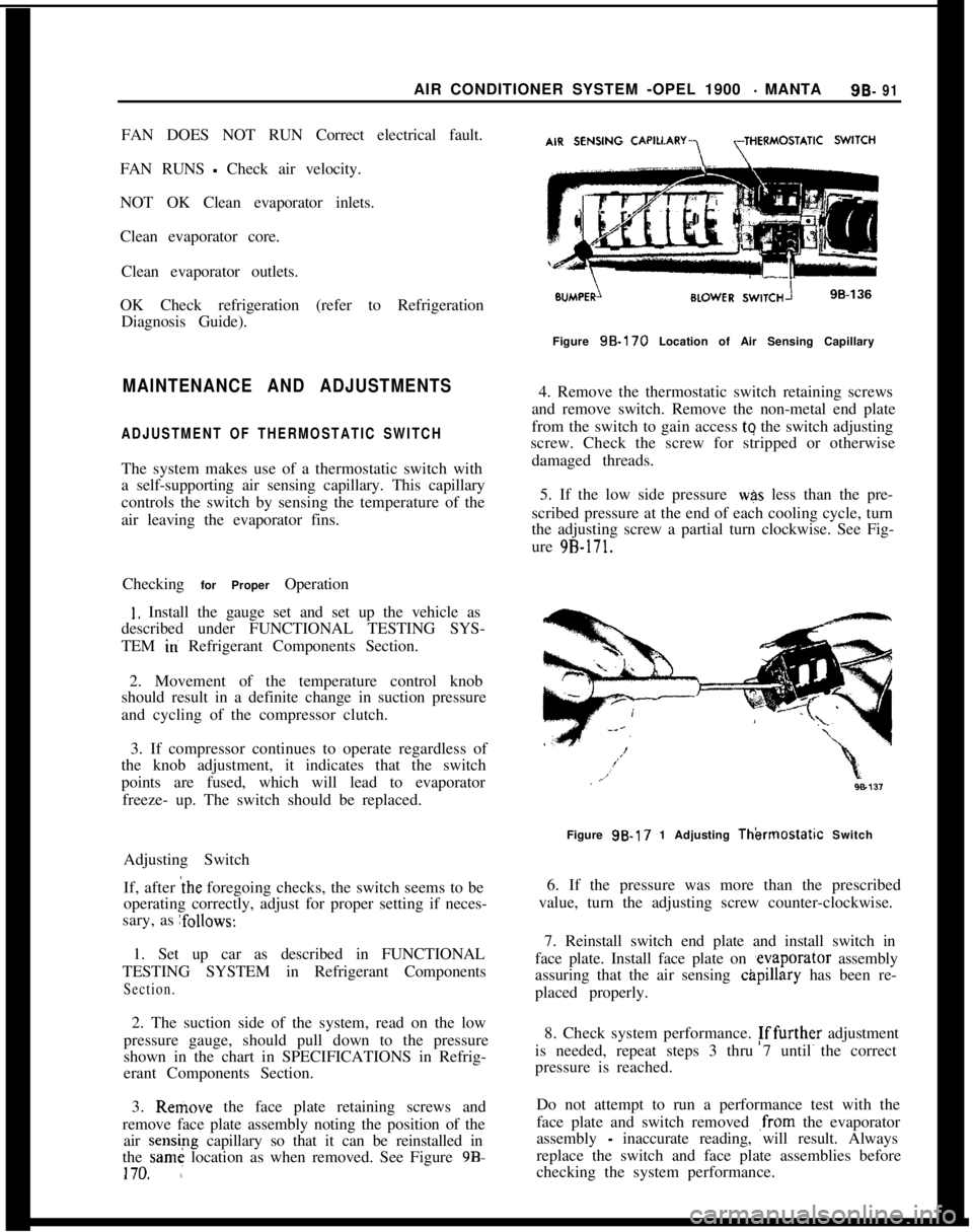
3. Remove the face plate retaining screws and
remove face plate assembly noting the position of the
air sensipg capillary so that it can be reinstalled in
the same location as when removed. See Figure 98.170. ,:Figure
98.170 Location of Air Sensing Capillary
4. Remove the thermostatic switch retaining screws
and remove switch. Remove the non-metal end plate
from the switch to gain access tq the switch adjusting
screw. Check the screw for stripped or otherwise
damaged threads.
5. If the low side pressure
was less than the pre-
scribed pressure at the end of each cooling cycle, turn
the adjusting screw a partial turn clockwise. See Fig-
ure
9B-171.Figure 9B-17 1 Adjusting
Thkmosfatic Switch
6. If the pressure was more than the prescribed
value, turn the adjusting screw counter-clockwise.
7. Reinstall switch end plate and install switch in
face plate. Install face plate on ,evaporator assembly
assuring that the air sensing
c&pillary has been re-
placed properly.
8. Check system performance. Fffurther adjustment
is needed, repeat steps 3 thru 7 until the correct
pressure is reached.
Do not attempt to run a performance test with the
face plate and switch removed
,from the evaporator
assembly
- inaccurate reading, will result. Always
replace the switch and face plate assemblies before
checking the system performance.
Page 605 of 625
AIR CONDITIONER SYSTEM - GT96. 97
AIR CONDITIONER SYSTEM
GTCONTENTS
Subject
: DESCRIPTION AND OPERATION:
General Description of System
. . . . . . . . . . . . . . . . . . . . . . . . . . . . . . . . . .Operation of Controls
. . . . . , . . . . . . . . . . . . . . . . . . . . . . . . . . . . . . . . . . . . . . . . . . . . . . .DIAGNOSIS:
Diagnosis Guide
. . . . . . . . . . . . . . . . . . . . . . . . . . . . . . . . . . . . . . . . . . . . . . . . . . . . . . . . . . . . . . . . . .MAINTENANCE AND ADJUSTMENTS:
Adjustment of Thermostatic Switch
. . . . . . . . . . . . . . . . . . . . . . .MAJOR REPAIR:
Removal 8 Installation of Vacuum Switch.
Removal&InstallationBlowerSwitch. . . . . . . . . . . . . . . . . . . . . .Removal & Installation Temperature Control Switch
. . . . . . . . . . . . . . . . . . . .
. . . . . . . . . . . . . . . . . . . . . . . . . . . . . . . . . . . . . . . . . . . . . . . . . . . . . . . . . . . . . . . . , . . . . . . . . . . . . . . . .
Removal&InstallationResistor Assembly. . . . . . . . . . . . . .Removal & Installation Blower Motor Assembly . .
SPECIFICATIONS:
Specifications
. . .
. . . . . . . . * . . . . . . . . . . . . . . . . . . . . . . . . . . . . . . . . . . . . . . . . . . . . . . . . . . . . . . . . . .Page No.
9BL 97
9Bi 97
9BL 98
98: 98
9B: 99
9B; 99
9B- 99
98~10098-101
9B-104
DESCRIPTION AND OPERATIONAir Knob
GENERAL DESCRIPTION OF SYSTEMTurning the AIR knob clockwise operates the three-
speed blower motor.
The air &mditioner is intended to give maximum
cooling comfort within the vehicle. To do this, care-
ful attention must be given to the following sections.
The system operates on recirculated air only and is
entirely @dependent of the vehicle heater.Temp Knob
Recirculated inside air is drawn into the unit, passed
through the evaporator core and into the car through
the adjustable outlets in the duct assembly.This knob may be regulated to cohtrol the degree of
cooling desired. Fully clock-wise provides maximum
cooling; however, turning the kndb to the center de-
tent position provides adequate cooling for highway
operation.
CONTROLSWhen maximum cooling is reqlired, outside air
should not be admitted to the car.
System c&trols are the AIR knob controlling the
three
spe&d blower motor switch and the TEMPWhen the unit is set for maximum cooling and the
vehicle is being driven continuously at highway
knob which controls the setting of the thermostaticspeeds or at elevations of 4,000 ft. or more, there is
switch. When operating this system, the heater musta possibility of the formation of ice on the evaporator
be off for maximum cooling.core tins.