ECU PEUGEOT 206 2002 Owners Manual
[x] Cancel search | Manufacturer: PEUGEOT, Model Year: 2002, Model line: 206, Model: PEUGEOT 206 2002Pages: 160, PDF Size: 2.03 MB
Page 13 of 160
9788
13YOUR 206 AT A GLANCE
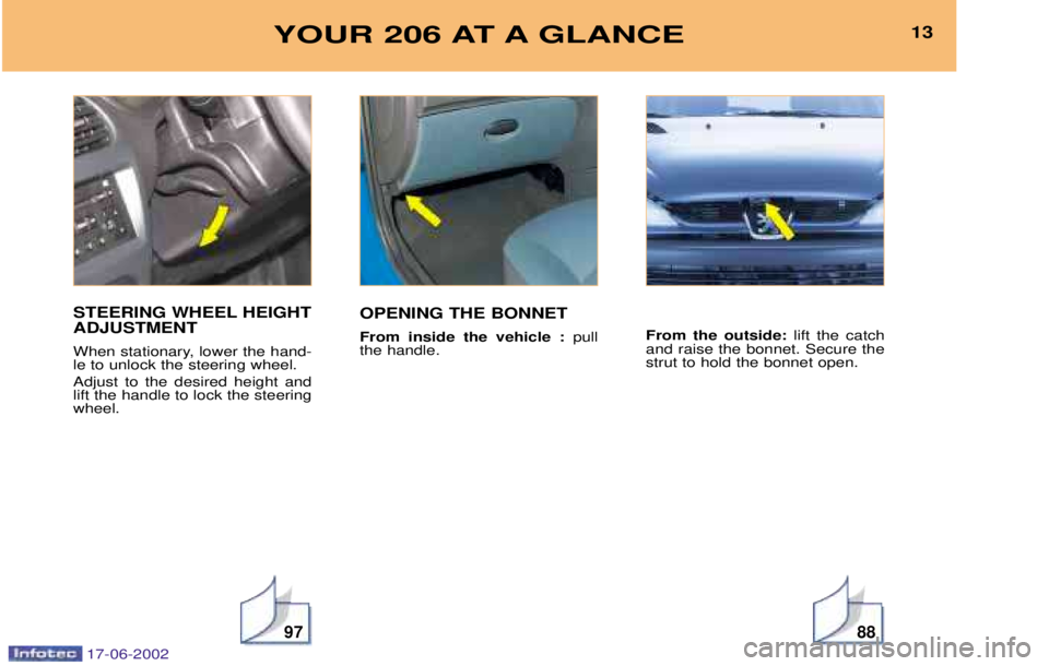
STEERING WHEEL HEIGHT ADJUSTMENT
When stationary, lower the hand- le to unlock the steering wheel. Adjust to the desired height and lift the handle to lock the steeringwheel.OPENING THE BONNET From inside the vehicle :
pull
the handle. From the outside:
lift the catch
and raise the bonnet. Secure the strut to hold the bonnet open.
17-06-2002
Page 87 of 160
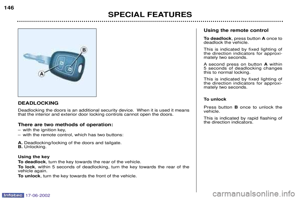
DEADLOCKING Deadlocking the doors is an additional security device. When it is used it means that the interior and exterior door locking controls cannot open the doors. There are two methods of operation:
Ð with the ignition key,
Ð with the remote control, which has two buttons: A.Deadlocking/locking of the doors and tailgate.
B. Unlocking.
Using the key
To deadlock , turn the key towards the rear of the vehicle.
To lock , within 5 seconds of deadlocking, turn the key towards the rear of the
vehicle again.
To unlock , turn the key towards the front of the vehicle. Using the remote control
To deadlock
, press button Aonce to
deadlock the vehicle. This is indicated by fixed lighting of the direction indicators for approxi-mately two seconds.
A second press on button Awithin
5 seconds of deadlocking changes this to normal locking. This is indicated by fixed lighting of the direction indicators for approxi-mately two seconds.
To unlock Press button Bonce to unlock the
vehicle. This is indicated by rapid flashing of the direction indicators.
SPECIAL FEATURES
146
17-06-2002
Page 90 of 160

THE ALARM* Setting and deactivating the alarm system Switching off the siren. The alarm completes the security
equipment for your vehicle. It offerstwo types of protection. Ðexternal protection : when it is set,
the alarm sounds if one of the doors, the boot or the bonnet isopened;
Ð internal protection : when it is set,
the alarm sounds if the sensorsdetect air movement in the pas-senger compartment (a brokenwindow) or movement within the
car.
The alarm also has an anti-tamperfunction. If there is an attempt to tamper with the wires to the siren, control unit or
the battery, the siren sounds and thedirection indicators light.
* According to destination Setting the alarm (external and internal protection)
Switch the ignition off and get out of the vehicle. Deadlock the vehicle.The doors lock.The direction indicators light for two seconds. The red light on the switch flashes once a second.
5 seconds later, internal protection is set.
45 seconds later, external protection is set. Note:
when the alarm is triggered, the
siren sounds for thirty seconds. After the thirty seconds it stops, but thealarm remains set.
Warning: When the alarm is set, if a
door, the tailgate or bonnet are not
closed correctly, the siren sounds fora moment. If the vehicle is closed cor-rectly in the following 45 seconds, thealarm is activated and the directionindicators remain on for two seconds.In all cases, the alarm is activatedafter 45 seconds. Disarming the alarm(internal and external protection) Press the release button of the remote
control key. The doors unlock.The direction indicators flash for two seconds. The red light on the switch goes out. Note:
if the warning light continues to
flash after de-activation of the alarm, it is a sign that the alarm has been
triggered. The flashing will stop whenthe ignition is switched on.
SPECIAL FEATURES
148
17-06-2002
Page 96 of 160

YOUR 206 IN DETAIL
88
BONNET STRUT Secure the strut to hold the bonnet open. Before closing the bonnet, replace the strut in its housing.
To close Lower the bonnet and release it at the end of its travel. Check that thebonnet is locked. FILLING THE FUEL TANK The tank must be filled with fuel with the
engine switched off .
Insert the key then turn it to the left. Remove the cap.
A label indicates which type of fuel to use. If you fill your tank, do not continue
after the third cut-off of the pump
nozzle. This could result in vehiclemalfunctions. The capacity of the tank is
approximately 50 litres.OPENING THE BONNET Inside the vehicle: pull the handle
on the left-hand side, under the fas- cia. Outside the vehicle: lift the catch
and raise the bonnet.
17-06-2002
Page 108 of 160
YOUR 206 IN DETAIL
100
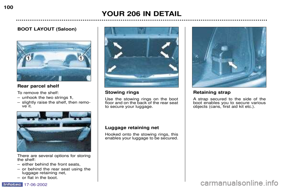
Stowing rings Use the stowing rings on the boot floor and on the back of the rear seatto secure your luggage. Luggage retaining net Hooked onto the stowing rings, this enables your luggage to be secured.
BOOT LAYOUT (Saloon)
Retaining strap
A strap secured to the side of the boot enables you to secure variousobjects (cans, first aid kit etc.).
Rear parcel shelf
To remove the shelf:
Ð unhook the two strings 1,
Ð slightly raise the shelf, then remo- ve it.
There are several options for storing the shelf:
Ð either behind the front seats,
Ð or behind the rear seat using theluggage retaining net,
Ð or flat in the boot.
17-06-2002
Page 110 of 160

YOUR 206 IN DETAIL103
BOOT LAYOUT (206 SW)
1. Grab handles and coat hooks
2. Coat hooks There are six hooks to accommodate coats.
3. High load retaining net fastenings The high load retaining net can be installed behind the front seats or behind the rear seat. Open the covers of the corresponding upper fastenings.
Install one end of the metal bar in one of the two fastenings, compress the bar, then install the other end and release.
Secure the two net strap hooks behind the front seats, with the rear seat folded down, or in the stowing rings on the floor.The rings are located directly below the corresponding upper fastenings.Pull the two straps taut.
4. Hooks
There are two side hooks on which to hang light bags.
5. 12V Socket for accessories This is a 12 volt socket (lighter type) installed on the the rear left trim and supplied from the accessories position (1stnotch).
6. Storage nets There are two nets (which cannot be removed) which can contain the luggage retaining net, a first aid kit etc.
7. Retaining straps There are two straps for securing various objects: cans etc.
8. Tonneau To install it:
Ð position one end of the tonneau roller in one of the two supports,
Ð compress the opposite end of the roller and position it,
Ð release it to allow it to engage,
Ð unroll the tonneau as far as the boot pillars,
Ð insert the tonneau guides in the rails in the pillars.
To remove it:
Ð remove the tonneau guides from the pillar rails,
Ð return the tonneau into its roller, compress it and remove it from its support.
9. Stowing rings There are eight stowing rings for securing the luggage retaining net: four on the rear seat back and four on the boot floor(two of which are under the carpet, at the far end of the boot).
Warning triangle The tailgate has a location intended for a warning triangle.
17-06-2002
Page 128 of 160
PRACTICAL INFORMATION
118
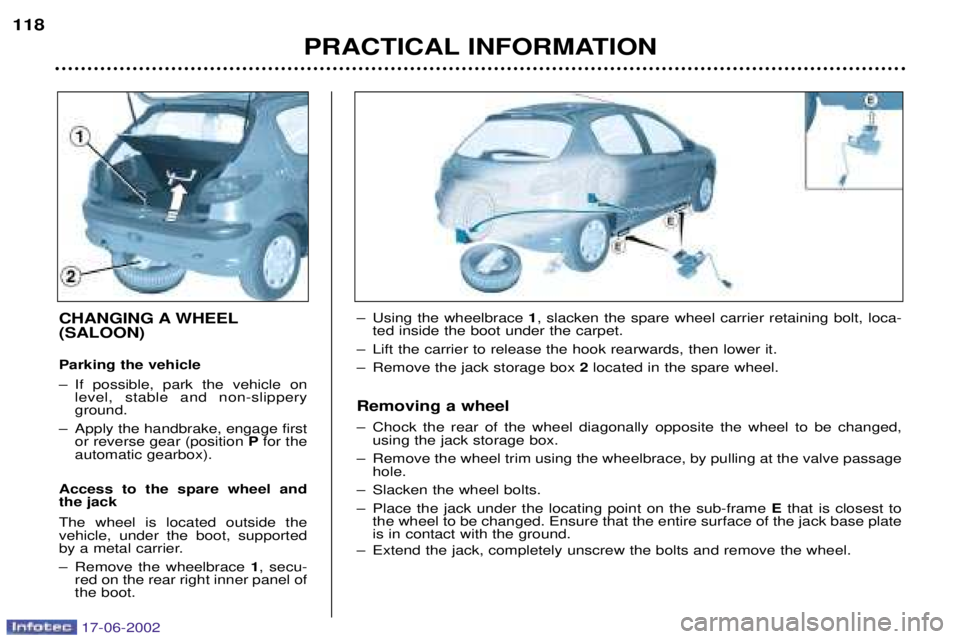
CHANGING A WHEEL (SALOON) Parking the vehicle
Ð If possible, park the vehicle on
level, stable and non-slippery ground.
Ð Apply the handbrake, engage first or reverse gear (position Pfor the
automatic gearbox).
Access to the spare wheel andthe jack The wheel is located outside the vehicle, under the boot, supported
by a metal carrier.
Ð Remove the wheelbrace 1, secu-
red on the rear right inner panel of the boot. Ð Using the wheelbrace
1, slacken the spare wheel carrier retaining bolt, loca-
ted inside the boot under the carpet.
Ð Lift the carrier to release the hook rearwards, then lower it.
Ð Remove the jack storage box 2located in the spare wheel.
Removing a wheel
Ð Chock the rear of the wheel diagonally opposite the wheel to be changed, using the jack storage box.
Ð Remove the wheel trim using the wheelbrace, by pulling at the valve passage hole.
Ð Slacken the wheel bolts.
Ð Place the jack under the locating point on the sub-frame Ethat is closest to
the wheel to be changed. Ensure that the entire surface of the jack base plate is in contact with the ground.
Ð Extend the jack, completely unscrew the bolts and remove the wheel.
17-06-2002
Page 130 of 160
PRACTICAL INFORMATION121
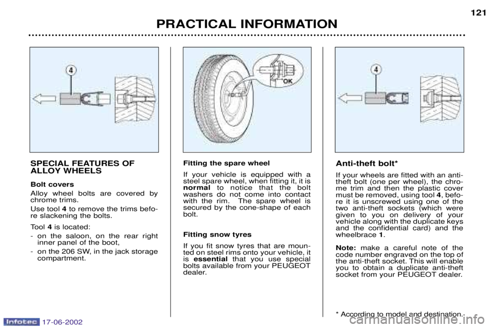
SPECIAL FEATURES OF
ALLOY WHEELS Bolt covers Alloy wheel bolts are covered by chrome trims. Use tool 4to remove the trims befo-
re slackening the bolts.
Tool 4is located:
- on the saloon, on the rear right inner panel of the boot,
- on the 206 SW, in the jack storage compartment. Fitting the spare wheelIf your vehicle is equipped with a steel spare wheel, when fitting it, it isnormal
to notice that the bolt
washers do not come into contact
with the rim. The spare wheel issecured by the cone-shape of eachbolt. Fitting snow tyres If you fit snow tyres that are moun- ted on steel rims onto your vehicle, itis essential that you use special
bolts available from your PEUGEOT
dealer. Anti-theft bolt* If your wheels are fitted with an anti- theft bolt (one per wheel), the chro-me trim and then the plastic covermust be removed, using tool
4, befo-
re it is unscrewed using one of thetwo anti-theft sockets (which weregiven to you on delivery of yourvehicle along with the duplicate keysand the confidential card) and thewheelbrace 1.
Note: make a careful note of the
code number engraved on the top of
the anti-theft socket. This will enableyou to obtain a duplicate anti-theft
socket from your PEUGEOT dealer.
* According to model and destination.
17-06-2002
Page 132 of 160
PRACTICAL INFORMATION119
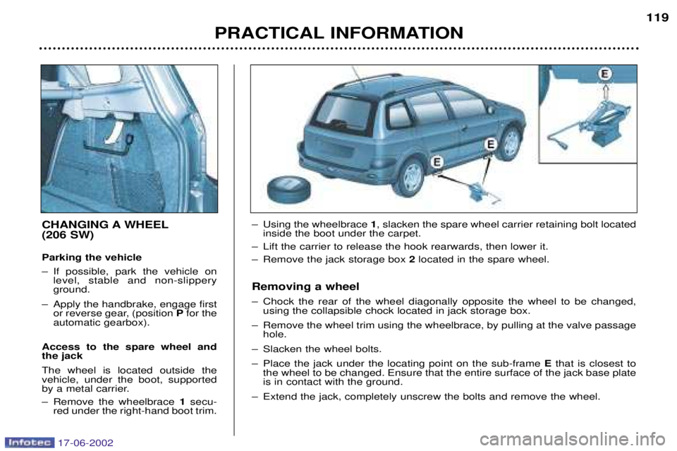
CHANGING A WHEEL (206 SW) Parking the vehicle
Ð If possible, park the vehicle on
level, stable and non-slippery ground.
Ð Apply the handbrake, engage first or reverse gear, (position Pfor the
automatic gearbox).
Access to the spare wheel andthe jack The wheel is located outside the vehicle, under the boot, supported
by a metal carrier.
Ð Remove the wheelbrace 1secu-
red under the right-hand boot trim. Ð Using the wheelbrace
1, slacken the spare wheel carrier retaining bolt located
inside the boot under the carpet.
Ð Lift the carrier to release the hook rearwards, then lower it.
Ð Remove the jack storage box 2located in the spare wheel.
Removing a wheel
Ð Chock the rear of the wheel diagonally opposite the wheel to be changed, using the collapsible chock located in jack storage box.
Ð Remove the wheel trim using the wheelbrace, by pulling at the valve passage hole.
Ð Slacken the wheel bolts.
Ð Place the jack under the locating point on the sub-frame Ethat is closest to
the wheel to be changed. Ensure that the entire surface of the jack base plate is in contact with the ground.
Ð Extend the jack, completely unscrew the bolts and remove the wheel.
17-06-2002
Page 134 of 160
PRACTICAL INFORMATION121
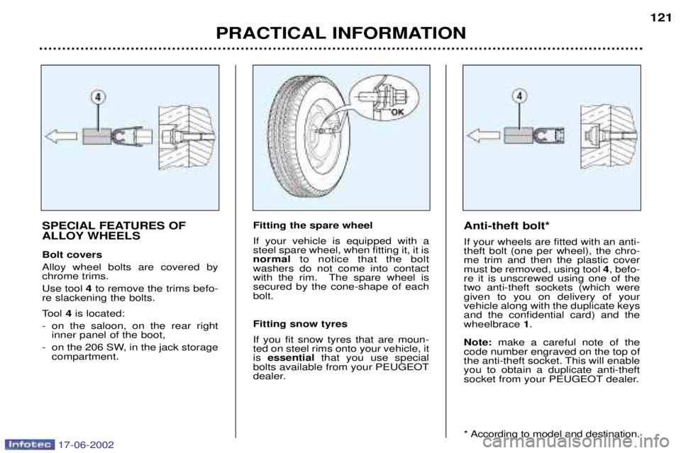
SPECIAL FEATURES OF
ALLOY WHEELS Bolt covers Alloy wheel bolts are covered by chrome trims. Use tool 4to remove the trims befo-
re slackening the bolts.
Tool 4is located:
- on the saloon, on the rear right inner panel of the boot,
- on the 206 SW, in the jack storage compartment. Fitting the spare wheelIf your vehicle is equipped with a steel spare wheel, when fitting it, it isnormal
to notice that the bolt
washers do not come into contact
with the rim. The spare wheel issecured by the cone-shape of eachbolt. Fitting snow tyres If you fit snow tyres that are moun- ted on steel rims onto your vehicle, itis essential that you use special
bolts available from your PEUGEOT
dealer. Anti-theft bolt* If your wheels are fitted with an anti- theft bolt (one per wheel), the chro-me trim and then the plastic covermust be removed, using tool
4, befo-
re it is unscrewed using one of thetwo anti-theft sockets (which weregiven to you on delivery of yourvehicle along with the duplicate keysand the confidential card) and thewheelbrace 1.
Note: make a careful note of the
code number engraved on the top of
the anti-theft socket. This will enableyou to obtain a duplicate anti-theft
socket from your PEUGEOT dealer.
* According to model and destination.
17-06-2002